


Ethernet Routing Switch
5510/5520/5530
Engineering
>Filters and QOS Configuration for Ethernet Routing Switch 5500 Technical Configuration Guide
Enterprise Solutions Engineering
Document Date: April 01, 2008
Document Number: NN48500-559
Document Version: 2.0

Filters and QoS Configuration for ERS 5500 |
|
|
Technical Configuration Guide |
v2.0 |
NN48500-559 |
Nortel is a recognized leader in delivering communications capabilities that enhance the human experience, ignite and power global commerce, and secure and protect the world’s most critical information. Serving both service provider and enterprise customers, Nortel delivers innovative technology solutions encompassing end-to-end broadband, Voice over IP, multimedia services and applications, and wireless broadband designed to help people solve the world’s greatest challenges. Nortel does business in more than 150 countries. For more information, visit Nortel on the Web at www.nortel.com.
Copyright © 2008 Nortel Networks. All Rights Reserved.
While the information in this document is believed to be accurate and reliable, except as otherwise expressly agreed to in writing NORTEL PROVIDES THIS DOCUMENT "AS IS" WITHOUT WARRANTY OR CONDITION OF ANY KIND, EITHER EXPRESS OR IMPLIED. The information and/or products described in this document are subject to change without notice. Nortel Networks, the Nortel Networks logo and the Globemark are trademarks of Nortel Networks.
___________________________________________________________________________________________________________________________
Nortel Confidential Information Copyright © 2008 Nortel Networks. All Rights Reserved. |
|
External Distribution |
1 |

Filters and QoS Configuration for ERS 5500 |
|
|
Technical Configuration Guide |
v2.0 |
NN48500-559 |
Abstract
This technical configuration guide provides an overview on how to configure QoS and Filters on the Ethernet Routing Switch 5500 with software release 5.1. The configuration examples are all in reference to the Nortel Networks Command Line Interface (NNCLI).
___________________________________________________________________________________________________________________________
Nortel Confidential Information Copyright © 2008 Nortel Networks. All Rights Reserved. |
|
External Distribution |
2 |

Filters and QoS Configuration for ERS 5500 |
|
|
Technical Configuration Guide |
v2.0 |
NN48500-559 |
Table of Contents
DOCUMENT UPDATES .................................................................................................................. |
5 |
||
CONVENTIONS............................................................................................................................... |
5 |
||
1. |
OVERVIEW: ETHERNET ROUTING SWITCH 5500 QOS AND FILTERING ........................ |
6 |
|
2. |
QOS FLOW CHART ................................................................................................................ |
9 |
|
3. |
FILTER FUNCTIONALITY .................................................................................................... |
10 |
|
|
3.1 |
OVERALL CLASSIFICATION FUNCTIONALITY ........................................................................ |
10 |
|
3.2 |
CLASSIFIER BLOCK FUNCTIONALITY .................................................................................. |
10 |
|
3.3 |
PORT RANGE FUNCTIONALITY........................................................................................... |
11 |
|
3.4 |
POLICIES ......................................................................................................................... |
12 |
4. |
QUEUE SETS........................................................................................................................ |
14 |
|
5. |
TRAFFIC METER AND SHAPING........................................................................................ |
19 |
|
|
5.1 |
ACTUAL BUCKET SIZE....................................................................................................... |
20 |
|
5.2 |
POLICING TRAFFIC ........................................................................................................... |
20 |
|
5.3 |
INTERFACE SHAPER ......................................................................................................... |
22 |
6. |
DEFAULT NORTEL CLASS OF SERVICE .......................................................................... |
24 |
|
7. |
QOS ACCESS LISTS (ACL) ................................................................................................. |
25 |
|
|
7.1 |
ACL CONFIGURATION....................................................................................................... |
25 |
8. |
IP SECURITY FEATURES .................................................................................................... |
30 |
|
|
8.1 |
DHCP SNOOPING ............................................................................................................ |
30 |
|
8.2 |
DYNAMIC ARP INSPECTION .............................................................................................. |
30 |
|
8.3 |
IP SOURCE GUARD .......................................................................................................... |
31 |
9. |
BPDU FILTERING ................................................................................................................. |
32 |
|
|
9.1 |
BPDU FILTERING CONFIGURATION ................................................................................... |
32 |
10. |
QOS INTERFACE APPLICATIONS.................................................................................. |
33 |
|
|
10.1 |
ARP SPOOFING ............................................................................................................... |
34 |
|
10.2 |
DHCP ATTACKS .............................................................................................................. |
35 |
|
10.3 |
DOS ................................................................................................................................ |
36 |
|
10.4 |
BPDU BLOCKING ............................................................................................................. |
37 |
11. CONFIGURATION STEPS – POLICY CONFIGURATION............................................... |
38 |
||
|
11.1 |
ROLE COMBINATION ......................................................................................................... |
38 |
|
11.2 |
CLASSIFICATION ............................................................................................................... |
39 |
|
11.3 |
METERS........................................................................................................................... |
41 |
|
11.4 |
ADD A NEW POLICY .......................................................................................................... |
42 |
12. |
CONFIGURATION EXAMPLES........................................................................................ |
43 |
|
|
12.1 |
PRE-DEFINED VALUES ...................................................................................................... |
43 |
|
12.2 |
CONFIGURATION EXAMPLE 1 – TRAFFIC METER USING POLICIES........................................ |
44 |
12.3CONFIGURATION EXAMPLE – IP ACL, DHCP SNOOPING, ARP INSPECTION, BPDU
FILTERING, AND SOURCE GUARD .................................................................................................. |
|
50 |
|
12.4 |
CONFIGURATION EXAMPLE 3: PORT RANGE USING ACL OR POLICY ................................... |
59 |
|
12.5 |
CONFIGURATION EXAMPLE 4 |
– L2 CLASSIFICATION BASED ON MAC ADDRESS ................... |
62 |
12.6 |
CONFIGURATION EXAMPLE 5 |
– L2 AND L3 CLASSIFICATION ................................................ |
64 |
___________________________________________________________________________________________________________________________ |
|||
|
Nortel Confidential Information Copyright © 2008 Nortel Networks. All Rights Reserved. |
|
|
|
|
External Distribution |
3 |

Filters and QoS Configuration for ERS 5500 |
|
|
Technical Configuration Guide |
v2.0 |
NN48500-559 |
12.7CONFIGURATION EXAMPLE 6 - QOS MARKING WITH PORT ROLE COMBINATION SET FOR UN-
RESTRICTED USING ACL’S ............................................................................................................ |
66 |
|
12.8 CONFIGURATION EXAMPLE 7 – INTERFACE SHAPING .......................................................... |
69 |
|
13. |
SOFTWARE BASELINE ................................................................................................... |
70 |
14. |
REFERENCE DOCUMENTATION.................................................................................... |
70 |
List of Figures |
|
Figure 1: QoS System Diagram ....................................................................................................... |
6 |
Figure 2: QoS Flow Chart ................................................................................................................ |
9 |
Figure 3: Arp Spoofing Example.................................................................................................... |
34 |
Figure 4: IP ACL, DHCP Snooping, ARP Inspection, and Source Guard ..................................... |
50 |
Figure 5: L2 Classification Based on MAC Address Example....................................................... |
62 |
Figure 6: DSCP Mapping via Un-restricted Port Role ................................................................... |
66 |
List of Tables |
|
Table 1: Default QoS Action ............................................................................................................ |
7 |
Table 2: Example of Valid Port Ranges......................................................................................... |
11 |
Table 3: Default Policy Drop Action ............................................................................................... |
12 |
Table 4: Ethernet Routing Switch 5500 Resource Sharing ........................................................... |
14 |
Table 5: Ethernet Routing Switch 5500 Egress CoS Queuing ...................................................... |
15 |
Table 6: Meter and Shaping Range and Granularity ..................................................................... |
19 |
Table 7: Actual Bucket Size in Bytes ............................................................................................. |
20 |
Table 8: Meter Bucket Size and Duration ...................................................................................... |
22 |
Table 9: Default Nortel CoS Markings ........................................................................................... |
24 |
Table 10: QoS Applications – Number of Classifiers Used ........................................................... |
33 |
___________________________________________________________________________________________________________________________
Nortel Confidential Information Copyright © 2008 Nortel Networks. All Rights Reserved. |
|
External Distribution |
4 |

Filters and QoS Configuration for ERS 5500 |
|
|
Technical Configuration Guide |
v2.0 |
NN48500-559 |
Document Updates
Added ACL, DHCP Snooping, APP Inspection, BPDU Filtering and IP Source Guard.
Conventions
This section describes the text, image, and command conventions used in this document.
Symbols:
&Tip – Highlights a configuration or technical tip.
Note – Highlights important information to the reader.
1Warning – Highlights important information about an action that may result in equipment damage, configuration or data loss.
Text:
Bold text indicates emphasis.
Italic text in a Courier New font indicates text the user must enter or select in a menu item, button or command:
ERS5520-48T# show running-config
Output examples from Nortel devices are displayed in a Lucinda Console font: ERS5520-48T# show running-config
!Embedded ASCII Configuration Generator Script
!Model = Ethernet Routing Switch 5520-24T-PWR
!Software version = v5.0.0.011
enable
configure terminal
___________________________________________________________________________________________________________________________
Nortel Confidential Information Copyright © 2008 Nortel Networks. All Rights Reserved. |
|
External Distribution |
5 |

Filters and QoS Configuration for ERS 5500 |
|
|
Technical Configuration Guide |
v2.0 |
NN48500-559 |
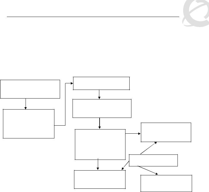
1.Overview: Ethernet Routing Switch 5500 QoS and Filtering
The Ethernet Routing Switch 5500 supports QoS and filter configuration via WEB, CLI, and Device Manager with no support for COPS at this time. As shown in the diagram below, the following functional components provide QoS support on the Ethernet Routing Switch 5500:
•Role Combination on the ingress port
•Classify traffic at either Layer 2 or at a Layer 3/4 level
•Take action by dropping, marking, redirecting, or metering (policing) traffic
•Send traffic to appropriate egress queue
Port
Port
Port
Port
Role Combinations (ingress port group)
Statistics / Counters
Classifier |
|
|
|
|
Queue |
||
|
|
||
|
|
|
|
|
|
Queue |
|
|
|
|
|
|
|
|
|
|
|
Queue |
|
Meter |
|||
|
|
||
|
|
|
|
|
|
|
|
Marker |
|
|
|
|
Queue |
||
|
|
||
|
|
|
Dropper
Redirecto
Actions
Egress ports
Figure 1: QoS System Diagram
Role Combination
A role combination is a grouping of one or more ports, capabilities, and interface classifications against which a policy is applied. The capabilities presently supported on the Ethernet Routing Switch 5500 include ingress IP and Layer 2 classification. The Ethernet Routing Switch 5500 supports the following interface classes that can be applied to zero, one, or many interfaces:
•Trusted Ports
o Assumes that all traffic coming into the port is originating from a trusted source. Therefore, the DSCP field of any traffic that enters the Ethernet Routing Switch 5500 from a Trusted Port is not remarked by default. However, a policy can still be applied to a trusted port to remark if required. Note that only the 802.1p user priority value associated with ‘well-known’ DSCP values are remapped by the default trusted
___________________________________________________________________________________________________________________________
Nortel Confidential Information Copyright © 2008 Nortel Networks. All Rights Reserved. |
|
External Distribution |
6 |

Filters and QoS Configuration for ERS 5500 |
|
|
Technical Configuration Guide |
v2.0 |
NN48500-559 |
polices. The ‘well-know’ DSCP values can be viewed by using the NNCLI command ‘show qos eqressmap’.
•Untrusted Ports
o Assumes that all traffic coming into the port is suspect. Therefore, the DSCP field of any traffic that enters the Ethernet Routing Switch 5500 from an Untrusted Port is remarked. For untagged packets, the default classifier is used to change the DSCP.
This results in a DSCP value determined by the CoS-to-DSCP mapping table using the default 802.1p priority of the interface where the packet is received. For tagged packets, the 802.1p value is determined by CoS-to-DSCP mapping table using the best effort DSCP, which is 0.
•Unrestricted Ports
o Does not assume anything about the origin of the incoming traffic. You may assign an action to set the DSCP or not to set the DSCP; it's up to you. This allows you to manipulate the DSCP value based upon the filter criteria, and not upon the point of origin.
The following table displays a summary of the role combination capabilities.
Table 1: Default QoS Action
Type of Filter |
Action |
Trusted |
Untrusted |
Unrestricted |
|
||||
|
|
|
|
|
|
|
|
• Tagged--Updates to 0 |
|
|
|
Does not |
(Standard) |
Does not |
|
DSCP |
• Untagged--Updates using |
||
|
change |
change |
||
IPv4 filter criteria |
|
mapping table and port’s |
||
|
|
|
||
|
|
default value |
|
|
or Layer 2 filter |
|
|
|
|
|
|
|
|
|
criteria matching |
|
|
|
|
IPv4 |
|
|
|
|
|
Updates |
|
|
|
|
|
|
|
|
|
IEEE |
based on |
Updates based on DSCP |
Does not |
|
DSCP |
|||
|
802.1p |
mapping table value |
change |
|
|
mapping |
|||
|
|
|
|
|
|
|
table value |
|
|
|
|
|
|
|
Classification
Classification identifies the traffic flow that requires QoS management. The traffic flow may be identified by the Layer 2 or IP content of the frame using any of the elements shown below.
Layer 2 Classifier Elements
o Source MAC with mask to filter on complete or partial MAC addresses
o Destination MAC with mask to filter on complete or partial MAC addresses
o VLAN ID – can be a range o Tagged or untagged packets o EtherType
o802.1p priority
•IP Classifier Elements
oSource IPv4/v6 host or subnet
___________________________________________________________________________________________________________________________
Nortel Confidential Information Copyright © 2008 Nortel Networks. All Rights Reserved. |
|
External Distribution |
7 |

Filters and QoS Configuration for ERS 5500 |
|
|
Technical Configuration Guide |
v2.0 |
NN48500-559 |
o Destination IPv4/v6 host or subnet o IPv4/v6 DSCP value
o IPv4 Protocol type, IPv6 next-header
o IPv4/v6 Layer 4 (UDP/TCP) Source port – can be range of ports
o IPv4/v6 Layer 4 (UDP/TCP) Destination port – can be range of ports o IPv6 flow identifier
A classifier can contain one Layer 2 element, one IP element, or one Layer 2 and one IP element. One or more classifiers can be combined to create a classifier block where up to 15 classifiers and/or classifier blocks can be assigned to a port. By using classifier blocks, the number of classifiers can be increased up to a total of 114 classifiers per port on the Ethernet Routing Switch 5500 for a total of over 40K in a stack. In addition, statistic counters can be used to match/in-profile and out-of-profile statistics with meter. Up to 32 match/in-profile counters and 63 out-of-profile counters (one per meter) are supported per interface.
Actions Supported
After matching a certain classification criteria, various actions can be initiated.
•In-profile actions (metered traffic within specific bandwidth limits)
o Drop
oUpdate DSCP
oUpdate 802.1p
oDrop precedence choice of low-drop, high-drop or use egress map
•Out-of-profile actions (metered traffic exceeding bandwidth limits)
oDrop
o Update DSCP
oSet drop precedence
•Non-Match actions (non-metered traffic)
oDrop
o Update DSCP
o Update 802.1p
o Drop precedence choice of low-drop or high-drop
Metering data includes in-profile and out-of-profile actions with metered bandwidth allocated per port. Each meter has its own token bucket that controls the rate at which packets are accepted for processing at ingress. The committed information rate (CIR) and bucket sizes are as follows:
oCommitted rate from 1 Mbps to 1 Gbps in 1 Mbps increments, 64K to 1 Gbps in 64K for ERS5530 only with 10/100/1000 Mbps interfaces – please see table 6 below for details
o Token bucket sizes in bytes: 16K, 20K, 32K, 44K, 76K, 140K, 268K, 512K where one byte is sent for each token
o Up to 63 counters are available per port
Statistics
The Ethernet Routing Switch 5500 supports tracking of statistics (packet counters) for the policies defined. The switch can be set-up for one counter for each classifier or a counter for all classifiers associated with a policy up to 63 counters are available per port. The statistics track match/inprofile and out-of-profile statistics associated with a meter.
___________________________________________________________________________________________________________________________
Nortel Confidential Information Copyright © 2008 Nortel Networks. All Rights Reserved. |
|
External Distribution |
8 |
Filters and QoS Configuration for ERS 5500 |
|
|
Technical Configuration Guide |
v2.0 |
NN48500-559 |
2. QoS Flow Chart
The following flowchart displays the various steps required in setting up a QoS policy. You basically now need to create a Classifier with each Classifier made up of one IP Classifier Element, or one L2 Classifier Element or one IP and one L2 Classifier Element. You then add the Classifier to a separate Policy on a per port basis. Or you can group a number of Classifiers into a Classifier Block and then add the Classifier Block to a Policy on a per port basis. The Ethernet Routing Switch 5500 supports up to 114 Classifiers per port for a total of greater than 40K Classifiers in a fully configured stack.
Role Combination
*Application > QoS > Devices
> Interface Configuration
Role Combination –
Interface Classes
o Trusted Ports
o Untrusted Ports
o Unrestricted
Classification
*Application > QoS > Rules
* WEB Configuration Step
Classifier Element
o IP Classifier Element
o L2 Classifier Element
Classifier
Made up of one of the following:
o One L2 Element o One IP Element
o One L2 and one IP
Policy
Type = Classifier
*Application QoS Policy
or
Meter
*Application QoS Meter
Classifier Block
Grouping of one or more Classifiers
Policy
 Type = Classifier Block
*Application QoS Policy
Figure 2: QoS Flow Chart
___________________________________________________________________________________________________________________________
Nortel Confidential Information Copyright © 2008 Nortel Networks. All Rights Reserved. |
|
External Distribution |
9 |
Filters and QoS Configuration for ERS 5500 |
|
|
Technical Configuration Guide |
v2.0 |
NN48500-559 |
3. Filter Functionality
3.1 Overall Classification Functionality
Classification with the Ethernet Routing Switch 5500 has some fundamental classification limitations, imposed by hardware, that affect classification overall. The foremost limitation is related to the concept, introduced by the latest classification hardware and the supporting data model, of “classification masks”. A classification mask specifies the fields within a frame that will be used for matching purposes. The mask itself does not specify the data to be matched but rather indicates which fields, or portions thereof, in the various protocol headers (e.g., MAC, IPv4, IPv6 headers) will be examined during the classification process. Currently, a maximum of 15 classification masks and 114 classifiers are available per port for user-defined traffic classification. This effectively means that 15 or fewer unique combinations of classification criteria (i.e., Layer 2, 3 and 4 data) can be specified per port. However, multiple data sets can leverage the same classification mask. This means that, as long as the same protocol data fields are being matched (e.g., IPv4 source address, IPv6 flow label, Layer 2 802.1p User Priority and VLAN Id), a much larger number of classifiers, up to a maximum of 114 per port, can be defined containing unique data values for matching against the fields/offsets identified by the classification mask.
3.2 Classifier Block Functionality
A user should take care when grouping a large number of individual classifiers into a classifier block. Grouping is a quick way to inadvertently exhaust limited resources. For example, a limited number of counters are available per interface for tracking matching/in-profile packets. Associating a block of classifiers with a policy indicating that statistics are to be maintained could consume all counting resources for a single interface with one policy. To avoid exhausting the number of counters available per interface, one may select "aggregate classifier tracking" instead of "individual classifier tracking" when creating the policy. By specifying "aggregate classifier tracking", a single counter resource is used to track statistics for all the classifiers of that policy, rather than a single counter resource per classifier. The obvious downside to this is the inability to track the statistics down to the granularity of each of the classifiers associated with the policy. Individual attribute limitations include:
•Individual classifier identification – a classifier set must exist prior to being referenced by the Classifier-Block.
•Individual classifier data compatibility – a classifier is eventually broken down into a bitmask identifying fields in a packet header that are of interest and values to be matched against those fields. Classifiers within a block must match the same protocol header fields, or portions thereof. For example, all classifiers in a block must match against an IPv4 source host address, an IPv4 source subnet with the same number of significant bits or the Layer 2 EtherType field in a tagged packet. A classifier matching against an IPv4 source host address and another matching against an IPv4 destination host address may not be members of the same block as these classifiers do not share a common classification mask. The values to be matched against may differ but the fields being matched may not.
Referenced component consistency – all the elements that comprise a block (i.e., all classifier blocks with the same block number) must either reference an action or a meter component or none of the elements are permitted to reference an action or a meter. In other words, all block members must specify the same type of information, be it action criteria, metering criteria or neither. The referenced action or metering elements may differ across block members but all members must reference individual actions or meters (but not actions and meters) if any do.
___________________________________________________________________________________________________________________________
Nortel Confidential Information Copyright © 2008 Nortel Networks. All Rights Reserved. |
|
External Distribution |
10 |

Filters and QoS Configuration for ERS 5500 |
|
|
Technical Configuration Guide |
v2.0 |
NN48500-559 |
Filter example:
a)IP Classifier #1: src IP = 10.1.1.0/24
b)IP Classifier #2: src IP = 10.20.0.0/16
c)IP Classifier #3: src IP = 172.1.1.0/24
d)IP Classifier #4: src IP = 10.22.0.0/16
e)IP Classifier #5: src IP = 10.1.2.0/24, dst IP = 192.1.1.0/24
f)IP Classifier #6: src = 10.1.10.0/24
Classifiers a, c and f can be combined to create a classifier block if you wish to filter on these addresses on a port(s). Classifiers b and d can be combined to create a second classifier block if you wish to filter on these addresses on a port(s).
3.3 Port Range Functionality
The Ethernet Routing Switch 5500 has the ability to specify a range of values supported by the QoS data model for several classification components (e.g., Layer 4 source and destination port numbers, VLAN Id values). Range support is limited to a certain extent, however, because ranges are represented as a bitmask within the overall classification mask, and not with explicit minimum and maximum values. A range must thus be specified by indicating which bits in the given field (e.g., Layer 4 source port) are ‘ignored’ (i.e., set to 0). Taking into account this limitation, the following rules are used to determine valid range values:
I.Minimum value: n Maximum value: n
>> Example: min: 20 max: 20 (min = max equates to a range of 1)
II.Minimum value: 0 Maximum value: (2^n) – 1
>>Example: min: 0 max: 63 (n = 6)
III.Minimum value: even number
Maximum value: minimum port number in binary with rightmost consecutive 0’s replaced with 1’s using the formula: Port Maximum = ((Port minimum + 2n) -1)) where n equal number of consecutive trailing zero’s.
>>Example: min: 128 max: 255 ((128 + 27) – 1 = 255; 128 in binary has 7 consecutive trailing zero’s)
Specified ranges that do not adhere to one of these three rules cannot be supported and will be flagged as erroneous.
The following table shows some examples of valid port ranges supported on the Ethernet Routing Switch 5500.
Table 2: Example of Valid Port Ranges
Minimum Value (must |
Maximum Value |
Binary Value |
be even number) |
|
|
0 |
1, 3, 7, 15, 31, 63, 127, |
|
|
255, 511, 1025, 2047, |
|
|
4095, 8191, 16355, |
|
|
32762, or 65535 |
|
2 |
3 |
Min = 10 |
___________________________________________________________________________________________________________________________
Nortel Confidential Information Copyright © 2008 Nortel Networks. All Rights Reserved. |
|
External Distribution |
11 |

Filters and QoS Configuration for ERS 5500 |
|
|
Technical Configuration Guide |
v2.0 |
NN48500-559 |
|
|
Max = 11 |
4 |
7 |
Min = 100 |
|
|
Max = 111 |
8 |
15 |
Min = 1000 |
|
|
Max = 1111 |
80 |
95 |
Min = 10100000 |
|
|
Max = 10111111 |
3.4Policies
•Packets received on an interface are matched against all policies associated with that interface. Hence, all policies are applied to the packet.
•Policy precedence – the precedence attribute is used to specify the evaluation order of policies that apply to the same interfaces. Policies with higher precedence (i.e., a larger value) are applied before those with lower precedence (i.e., a smaller value). Precedence values must be unique for all policies being applied to the same interface role.
•If one policy associated with the specific interface only specifies a value updating the DSCP value while another policy associated with that same interface only specifies a value for updating the 802.1p user priority value, both of these actions occur.
•If two policies on the specified interface request that the DSCP be updated but specify different values - the value from the policy with the higher precedence will be used.
•Referenced component conflicts - action or meter criteria can be specified through individual classifier blocks. When a policy references a classifier block and members of the referenced block identify their own action or meter criteria, action and meter data must not be specified by the policy.
•The actions applied to packets include those actions defined from user-defined policies and those actions defined from system default policies. The user-defined actions always carry a higher precedence than the system default actions. This means that, if userdefined policies do not specify actions that overlap with the actions associated with system default policies (for example, the DSCP and 802.1p update actions installed on untrusted interfaces), the lowest precedence, default policy actions will be included in the set of actions to be applied to the identified traffic.
•The following table displays the ERS 5500 default policy action with corresponding drop actions. The drop action specifies whether a packet should be dropped, not dropped, or deferred. A drop action of deferred-Pass specifies that a traffic flow decision will be deferred to other installed policies.
Table 3: Default Policy Drop Action
ID |
Name |
Drop |
Update DSCP |
User Priority |
Drop |
|
|
|
|
|
Precedence |
1 |
Drop_Traffic |
drop |
Ignore |
Ignore |
highDropPrec |
2 |
Standard_Service |
Don’t Drop |
0x00 |
Priority 0 |
highDropPrec |
3 |
Bronze_Service |
Don’t Drop |
0x0a |
Priority 2 |
lowDropPrec |
4 |
Silver_Service |
Don’t Drop |
0x12 |
Priority 3 |
lowDropPrec |
5 |
Gold_Service |
Don’t Drop |
0x1a |
Priority 4 |
lowDropPrec |
6 |
Platinum_Service |
Don’t Drop |
0x22 |
Priority 5 |
lowDropPrec |
7 |
Premium_Service |
Don’t Drop |
0x2e |
Priority 6 |
lowDropPrec |
8 |
Network_Service |
Don’t Drop |
0x30 |
Priority 7 |
lowDropPrec |
9 |
Null_Service |
Don’t Drop |
ignore |
ignore |
lowDropPrec |
___________________________________________________________________________________________________________________________
Nortel Confidential Information Copyright © 2008 Nortel Networks. All Rights Reserved. |
|
External Distribution |
12 |

Filters and QoS Configuration for ERS 5500 |
|
|
Technical Configuration Guide |
v2.0 |
NN48500-559 |
When setting up multiple policies using any of the default policy actions ID’s 2 to 9 (i.e. Standard_Service, Bronze_Service, etc) a lower precedence policy with a drop action, (i.e. Drop_Traffic), the Drop_Traffic action will effect the higher precedence policies. The end result is all the higher precedence policies will also be dropped. The reason for this is each of the default actions, with the exception of Drop_Traffic, uses a drop action of deferred-Pass. A drop action of deferred-Pass specifies that a traffic flow decision will be deferred to other installed policies.
To make a policy behave somewhat similar to stop-on-match, you will have to create a new action with a drop action of dontDrop (JDM) or disable (CLI).
•Statistics accumulation support – a limited number of counters are available for tracking statistics. Specifically, 32 counters are available per port for tracking matching (no metering specified) /in-profile (metering specified) traffic statistics. A total of 63 counters are available (per port) to track out-of-profile statistics, with the caveat that these counters are associated with the metering component and flows sharing the same meter on the same port use the same counter for statistics.
The valid precedence range for QoS policies is from 1 to 15. However, depending on the application enabled, the valid precedence range can change as QoS shares resources with other switch applications including DHCP Relay, MAC Security, IP Fix, IGMP, EAPOL, EAP multihost (5530-24TFD only), OSPF, IP Source Guard, and ADAC. Please use the command ‘show qos diag’ to view the mask utilization per port.
In release 4.1, FCS November 2004, the system default actions (e.g. bronze, silver, gold, etc.) will be changed from deferred-Pass to dontDrop.
___________________________________________________________________________________________________________________________
Nortel Confidential Information Copyright © 2008 Nortel Networks. All Rights Reserved. |
|
External Distribution |
13 |

Filters and QoS Configuration for ERS 5500 |
|
|
Technical Configuration Guide |
v2.0 |
NN48500-559 |
4. Queue Sets
Prior to software release 4.0, the Ethernet Routing Switch 5500 supported a single queue set with eight queues, one absolute queue and seven WRR queues.
With the introduction of software release 4.0, eight different queue sets where made available. Each queue set has different characteristics in regards to number of queues and service weights allowing the user to select a queue set based on the user’s particular needs. With eight queue settings and three resource sharing options, the Ethernet Routing Switch 5500 supports a total of 24 different queues and buffer setting combinations. Prior to making any changes to the egress queue, the buffer resource sharing feature must be enabled.
Resource Sharing
The three (3) possible resource sharing settings in version 4.0 or greater software release are regular, large, and maximum. These settings allow the user to change the amount of buffer which can be allocated or shared to any port. Note that the switch must be rebooted if any changes are made.
|
Table 4: Ethernet Routing Switch 5500 Resource Sharing |
|
|
Setting |
Description |
Regular |
1 port may use up to 16% of the buffers for a group of 12 ports. |
|
|
Large |
1 port may use up to 33% of the buffers for a group of 12 ports. |
|
|
Maximum |
1 port may use 100% of the buffers for a group of 12 ports. |
|
|
Resource Sharing Commands
•5520-24T-PWR(config)# qos agent buffer <large | maximum | regular>
The qos agent buffer <regular | large | maximum > command allows the user to specify the level of resource sharing on the switch. This parameter is global and requires a reset to activate a change. This command is in the CLI priv-exec mode.
•5520-24T-PWR(config)# default qos agent buffer
The default qos agent buffer command sets the switches agent buffer back to a default setting of regular. In order for this command to take affect, a reset of the switch must occur. This command is in the CLI priv-exec mode.
Resource Sharing Recommendations
Nortel Networks recommends you use the default resource-sharing setting of regular. If you change the setting, the resulting performance may increase for some ports, and at times, decrease for other ports.
Generally speaking, smaller buffers achieve lower latency (RTT) but reduce the throughput ability which is better for VoIP etc. and sensible jitter application.
You should use the Maximum resource sharing setting:
•If you are using your 5520 for big file transfers (like backup of servers)
___________________________________________________________________________________________________________________________
Nortel Confidential Information Copyright © 2008 Nortel Networks. All Rights Reserved. |
|
External Distribution |
14 |
Filters and QoS Configuration for ERS 5500 |
|
|
Technical Configuration Guide |
v2.0 |
NN48500-559 |
•If you are using (the AppleTalk Filing Protocol) AFP, use large or maximum resource sharing (AFP use a fix windows size set to 65,535K).You should use the large resource sharing setting:
•If you are using your 5520 for high bandwidth application such as video.
•If you are using large TCP windows for your traffic, use large resource sharing (you can also reduce the TCP windows size on windows operating system - see Microsoft TechNet article 224829).
•If you have 4 or fewer ports connected per group of 12 ports.
You should use the Regular resource sharing setting:
•If you are using your 5520 in a VOIP environment.
•If you have 5 or more ports connected per group of 12 ports.
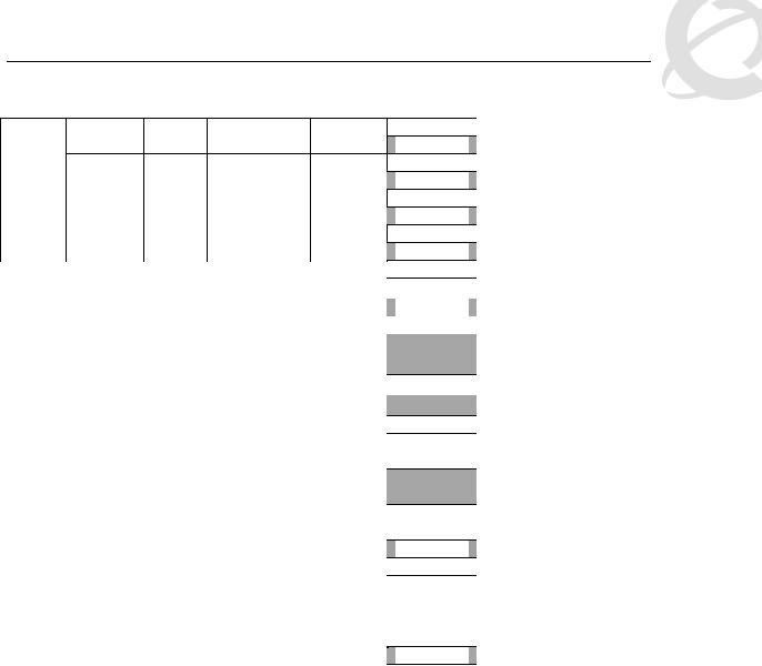
Egress CoS Queuing
The following charts describe each possible egress CoS queuing setting. The mapping of 802.1p priority to egress CoS queue, dequeuing algorithm, and queue weight is given. Additionally, the memory and maximum number of packets which can be buffered per egress CoS queue and resource sharing settings is shown.
Setting
8 CoS
Table 5: Ethernet Routing Switch 5500 Egress CoS Queuing |
|
|||||||||
|
|
|
|
|
|
|
Regular |
|
|
|
|
|
|
|
|
|
|
Large |
Max |
||
Internal |
Egress |
|
Dequeuing |
Weight |
|
Memory/ |
Memory/ # |
Memory/ # |
||
CoS |
|
|
||||||||
Priority |
|
Algorithm |
|
# of 1518 |
of 1518 |
of 1518 |
||||
Queue |
|
|
|
|||||||
|
|
|
|
|
|
Byte |
Byte |
Byte |
||
|
|
|
|
|
|
|
||||
|
|
|
|
|
|
|
Packets |
Packets |
Packets |
|
7 |
1 |
|
Strict |
100% |
|
36864B |
49152B |
131072B |
||
|
|
24 |
|
32 |
86 |
|||||
|
|
|
|
|
|
|
|
|||
6 |
2 |
|
|
|
41% |
|
36864B |
47104B |
123392B |
|
|
|
|
|
|||||||
|
|
|
|
24 |
|
31 |
81 |
|||
|
|
|
|
|
|
|
|
|||
5 |
3 |
|
|
|
19% |
|
27648B |
45056B |
115712B |
|
|
|
|
|
18 |
|
29 |
76 |
|||
|
|
|
|
|
|
|
|
|||
4 |
4 |
|
|
|
13% |
|
18432B |
43008B |
108032B |
|
|
|
|
|
12 |
|
28 |
71 |
|||
|
|
|
|
|
|
|
|
|||
3 |
5 |
|
Weighted |
|
11% |
|
18432B |
39936B |
97792B |
|
|
Round Robin |
|
|
12 |
|
26 |
64 |
|||
|
|
|
|
|
|
|
||||
2 |
6 |
|
|
|
8% |
|
18432B |
36864B |
85504B |
|
|
|
|
|
12 |
|
24 |
56 |
|||
|
|
|
|
|
|
|
|
|||
1 |
7 |
|
|
|
5% |
|
18432B |
33792B |
70656B |
|
|
|
|
|
12 |
|
22 |
46 |
|||
|
|
|
|
|
|
|
|
|||
0 |
8 |
|
|
|
3% |
|
18432B |
30720B |
54272B |
|
|
|
|
|
12 |
|
20 |
35 |
|||
|
|
|
|
|
|
|
|
|||
7 CoS
7 |
1 |
|
Strict |
100% |
|
36864B |
49152B |
144640B |
||
|
|
24 |
|
32 |
95 |
|||||
|
|
|
|
|
|
|
|
|||
6 |
2 |
|
Weighted |
|
45% |
|
32768B |
46080B |
131840B |
|
|
Round Robin |
|
|
21 |
|
30 |
86 |
|||
|
|
|
|
|
|
|
||||
5 |
3 |
|
|
|
21% |
|
26624B |
39936B |
120064B |
|
|
|
|
|
17 |
|
26 |
79 |
|||
|
|
|
|
|
|
|
|
|||
4 |
4 |
|
|
|
15% |
|
19968B |
33280B |
109824B |
|
|
|
|
|
13 |
|
21 |
72 |
|||
|
|
|
|
|
|
|
|
|||
___________________________________________________________________________________________________________________________
Nortel Confidential Information Copyright © 2008 Nortel Networks. All Rights Reserved. |
|
External Distribution |
15 |
Filters and QoS Configuration for ERS 5500 |
|
|
Technical Configuration Guide |
v2.0 |
NN48500-559 |
6 CoS
5 CoS
3 |
5 |
|
|
|
10% |
|
18432B |
|
31232B |
|
100864B |
|||
|
|
|
|
12 |
|
|
20 |
|
|
66 |
|
|||
|
|
|
|
|
|
|
|
|
|
|
|
|||
2 |
6 |
|
|
|
6% |
|
18432B |
|
31232B |
|
92800B |
|||
|
|
|
|
12 |
|
|
20 |
|
|
61 |
|
|||
|
|
|
|
|
|
|
|
|
|
|
|
|||
1 |
7 |
|
|
|
3% |
18432B |
|
31232B |
|
86400B |
||||
0 |
|
|
|
|
12 |
|
|
20 |
|
|
56 |
|
||
|
|
|
|
|
|
|
|
|
|
|
||||
|
|
|
|
|
|
|
36864B |
|
|
|
|
|
||
7 |
1 |
|
Strict |
100% |
|
|
51200B |
|
163840B |
|||||
|
|
24 |
|
|
33 |
|
|
107 |
|
|||||
|
|
|
|
|
|
|
|
|
|
|
|
|||
6 |
2 |
|
|
|
52% |
|
33792B |
|
49152B |
|
151040B |
|||
|
|
|
|
22 |
|
|
32 |
|
|
99 |
|
|||
|
|
|
|
|
|
|
|
|
|
|
|
|||
5 |
3 |
|
|
|
24% |
|
31744B |
|
47104B |
|
137472B |
|||
|
|
|
|
20 |
|
|
31 |
|
|
90 |
|
|||
|
|
|
|
|
|
|
|
|
|
|
|
|||
4 |
4 |
|
Weighted |
|
14% |
|
26624B |
|
43008B |
|
124160B |
|||
|
Round Robin |
|
|
17 |
|
|
28 |
|
|
81 |
|
|||
|
|
|
|
|
|
|
|
|
|
|
||||
3 |
5 |
|
|
|
7% |
21504B |
|
37376B |
111360B |
|||||
2 |
|
|
|
|
14 |
|
24 |
|
73 |
|
||||
|
|
|
|
|
|
|
|
|
||||||
1 |
6 |
|
|
|
3% |
18432B |
|
34304B |
|
98560B |
||||
0 |
|
|
|
|
12 |
|
22 |
|
64 |
|
||||
|
|
|
|
|
|
|
|
|
||||||
|
|
|
|
|
|
|
46080B |
|
|
|
|
|||
7 |
1 |
|
Strict |
100% |
|
|
64000B |
|
199680B |
|||||
|
|
30 |
|
|
42 |
|
|
131 |
|
|||||
|
|
|
|
|
|
|
|
|
|
|
|
|||
6 |
2 |
|
|
|
58% |
|
41984B |
|
59904B |
|
181760B |
|||
|
|
|
|
|
|
|||||||||
|
|
|
|
27 |
|
|
39 |
|
|
119 |
|
|||
|
|
|
|
|
|
|
|
|
|
|
|
|||
5 |
3 |
|
|
|
27% |
35840B |
53760B |
158720B |
||||||
4 |
|
Weighted |
|
|
23 |
|
|
35 |
|
|
104 |
|
||
|
|
|
|
|
|
|
|
|
|
|||||
3 |
4 |
|
Round Robin |
|
11% |
28160B |
46080B |
133120B |
||||||
2 |
|
|
|
|
18 |
|
|
30 |
|
|
87 |
|
||
|
|
|
|
|
|
|
|
|
|
|
||||
1 |
5 |
|
|
|
4% |
19968B |
38400B |
113152B |
||||||
0 |
|
|
|
|
13 |
|
|
25 |
|
|
74 |
|
||
|
|
|
|
|
|
|
|
|
|
|
||||
___________________________________________________________________________________________________________________________
Nortel Confidential Information Copyright © 2008 Nortel Networks. All Rights Reserved. |
|
External Distribution |
16 |
Filters and QoS Configuration for ERS 5500 |
|
|
Technical Configuration Guide |
v2.0 |
NN48500-559 |
7 |
1 |
Strict |
100% |
|
6 |
||||
|
|
|
CoS |
5 |
2 |
|
|
|
65% |
|
|
|
|
|||
|
4 |
|
|
|
||
|
|
|
|
|
|
|
4 |
3 |
3 |
|
Weighted |
|
26% |
2 |
|
Round Robin |
|
|||
|
|
|
|
|||
|
1 |
4 |
|
|
|
9% |
|
0 |
|
|
|
||
|
|
|
|
|
|
|
|
|
|
|
|
|
|
|
7 |
1 |
|
Strict |
100% |
|
CoS |
6 |
|
||||
|
|
|
|
|
||
5 |
|
|
|
|
|
|
|
|
|
|
|
|
|
|
4 |
2 |
|
Weighted |
|
75% |
3 |
3 |
|
|
|
|
|
|
|
Round Robin |
|
|
||
2 |
3 |
|
|
25% |
||
|
|
|
|
|||
|
1 |
|
|
|
||
|
|
|
|
|
|
|
|
|
|
|
|
|
|
|
7 |
|
|
|
|
|
CoS |
6 |
1 |
|
Strict |
100% |
|
5 |
|
|||||
|
|
|||||
|
|
|
|
|
|
|
|
4 |
|
|
|
|
|
2 |
3 |
2 |
|
Weighted |
|
100% |
2 |
|
|
||||
|
|
Round Robin |
|
|||
|
1 |
|
|
|
|
|
|
|
|
|
|
|
|
|
|
|
|
|
|
|
CoS |
7 |
|
|
|
|
|
6 |
|
|
|
|
|
|
|
|
|
|
|
|
|
|
5 |
1 |
|
Strict |
100% |
|
1 |
4 |
|
|
|
|
|
3 |
|
|
|
|
|
|
|
|
|
|
|
|
|
Egress CoS Queuing CLI Commands |
|
|||||
57344B |
81920B |
262912B |
||||
|
37 |
|
|
53 |
|
173 |
51200B |
74240B |
209920B |
||||
|
33 |
|
|
48 |
|
138 |
38912B |
61440B |
176640B |
||||
|
25 |
|
|
40 |
|
116 |
24576B |
44544B |
136960B |
||||
|
16 |
|
|
29 |
|
90 |
|
|
|
||||
65536B |
109568B |
393316B |
||||
|
43 |
|
72 |
259 |
||
57344B |
87040B |
262144B |
||||
|
|
|
|
|
|
|
37 |
|
57 |
172 |
|||
|
|
|
||||
49152B |
65536B |
131072B |
||||
|
32 |
|
|
43 |
|
86 |
|
|
|
|
|||
|
106496B |
180224B |
524288B |
|||
|
|
|
|
|||
|
|
|
|
|
|
|
70 |
|
118 |
345 |
|||
|
|
|
|
|
|
|
|
61440B |
|
81920B |
|
262144B |
|
|
|
|
|
|
||
|
40 |
|
53 |
172 |
||
|
|
|
|
|||
|
131072B |
262144B |
786432B |
|||
|
|
|
|
|
||
|
86 |
|
172 |
518 |
||
•5520-24T-PWR(config)#show qos queue-set-assignment
The show qos queue-set-assignment command displays in the CLI the 802.1p priority to egress CoS and QoS queue mapping for CoS setting 1-8. This command is in the CLI priv-exec mode.
•5520-24T-PWR(config)#show qos queue-set
The show qos queue-set command displays the queue set configuration. The display includes the general discipline of the queue, the percent bandwidth (Kbps), and the queues size in bytes. This command is in the CLI priv-exec mode.
•5520-24T-PWR(config)#qos agent queue set <1-8>
The qos agent queue set <1-8> command sets the egress CoS and QoS queue mode (1- 8) in which the switch will operate. This parameter is global and requires a reset to activate a change. This command is in the CLI priv-exec mode.
•5520-24T-PWR(config)#qos queue-set-assignment queue-set <1-8> 1p <0-7> queue
<1-8>
___________________________________________________________________________________________________________________________
Nortel Confidential Information Copyright © 2008 Nortel Networks. All Rights Reserved. |
|
External Distribution |
17 |

Filters and QoS Configuration for ERS 5500 |
|
|
Technical Configuration Guide |
v2.0 |
NN48500-559 |
The qos queue-set-assignment queue-set <1-8> 1p <0-7> queue <1-8> command gives the user the ability to specify the queue to associate an 802.1p priority. This command is in the CLI priv-exec mode.
•5520-24T-PWR(config)#default qos agent queue-set
The default qos agent queue-set command will default the egress CoS and QoS queue set. The default CoS/QoS queue mode is 8. This command is in the CLI priv-exec mode.
•5520-24T-PWR(config)#show qos agent
The show qos agent command displays the current attributes for egress CoS and QoS queue mode, resource sharing mode and QoS NVRAM commit delay. This command is in the CLI priv-exec mode.
•5520-24T-PWR(config)#qos agent nvram delay
The qos agent nvram delay command will modify the maximum time in seconds to write config data to non-volatile storage. This command is in the CLI priv-exec mode.
•5520-24T-PWR(config)#qos agent reset-default
The qos agent reset-default command resets QoS to its configuration default. This command is in the CLI priv-exec mode.
Egress Queue Recommendations
If you are running all untagged traffic and do not change default port priority settings, use setting 1 CoS.
___________________________________________________________________________________________________________________________
Nortel Confidential Information Copyright © 2008 Nortel Networks. All Rights Reserved. |
|
External Distribution |
18 |

Filters and QoS Configuration for ERS 5500 |
|
|
Technical Configuration Guide |
v2.0 |
NN48500-559 |
5. Traffic Meter and Shaping
The Ethernet Routing Switch 5500 supports both policing/metering of ingress traffic in addition to egress port shaping. The meter and shape range is as shown in table 6 below. Please note that all QoS levels are respected and honoured on a shaped interface.
Table 6: Meter and Shaping Range and Granularity
Product |
Meter/Shaper Range |
Granularity |
Bucket Size |
ERS5510 |
1 Mbps to 1023 Mbps |
1 Mbps |
8 buckets |
ERS5520 |
1 Mbps to 1023 Mbps |
1 Mbps |
8 buckets |
ERS5530 |
64 Kbps to 1023 |
64 Kbps |
8 buckets |
(10M/100M,1G) |
Mbps |
|
|
ERS5530 (10G) |
1 Mbps to 1023 Gbps |
1 Mbps |
12 buckets |
When configuring traffic metering or shaping, a committed rate, a maximum burst size and burst duration is entered. The maximum burst rate and burst duration is used along with the committed rate to setup a fixed token bucket where each token represents 1 byte. Up to eight fixed bucket sizes are supported for all 10/100 Mbps and GigE ports. Up to twelve fixed bucket sizes are supported on the ERS5530 only via the 10 GigE interface. The token bucket allows a committed burst to occur up to the token bucket size.
For traffic metering, an in profile and an out of profile action is configured and is expressed as an id. You can use one of the default actions or create a new action prior to configuring a meter. To view the action id’s, please use the command shown below. For example, if you wish to remark the in profile traffic with a QoS level of Bronze and drop traffic for out of profile traffic, select id 3 and 1 respectively. Please note that you must associate the classifier to identify IP traffic since the DSCP value is being remarked.
•5530-24TFD(config)#show qos action
Id |
Name |
Drop |
Update |
802.1p |
Set Drop Extension |
Storage |
|
|
|
DSCP |
Priority |
Precedence |
Type |
_____ ________________ _____ ______ |
____________ |
___________ _________ |
_______ |
|||
1 |
Drop_Traffic |
Yes |
Ignore |
Ignore |
High Drop |
ReadOnl |
2 |
Standard_Service |
No |
0x0 |
Priority 0 |
High Drop |
ReadOnl |
3 |
Bronze_Service |
No |
0xA |
Priority 2 |
Low Drop |
ReadOnl |
4 |
Silver_Service |
No |
0x12 |
Priority 3 |
Low Drop |
ReadOnl |
5 |
Gold_Service |
No |
0x1A |
Priority 4 |
Low Drop |
ReadOnl |
6 |
Platinum_Service |
No |
0x22 |
Priority 5 |
Low Drop |
ReadOnl |
7 |
Premium_Service |
No |
0x2E |
Priority 6 |
Low Drop |
ReadOnl |
8 |
Network_Service |
No |
0x30 |
Priority 7 |
Low Drop |
ReadOnl |
9 |
Null_Action |
No |
Ignore |
Ignore |
Low Drop |
ReadOnl |
55001 |
UntrustedClfrs1 |
DPass |
Ing 1p |
Ignore |
Low Drop |
Other |
55002 |
UntrustedClfrs2 |
DPass |
0x0 |
Priority 0 |
High Drop |
Other |
.
___________________________________________________________________________________________________________________________
Nortel Confidential Information Copyright © 2008 Nortel Networks. All Rights Reserved. |
|
External Distribution |
19 |
Filters and QoS Configuration for ERS 5500 |
|
|
Technical Configuration Guide |
v2.0 |
NN48500-559 |
5.1 Actual Bucket Size
When configuring a meter or shape rate, a fixed token bucket is also configured which is derived from the committed rate, burst rate, and burst duration configured. If a burst duration is not configured, the largest bucket size is automatically selected which would be 512K for a 10/100 Mbps or 1 GigE port. If you wish to use another bucket size, you must calculate the burst duration by using the actual size of the bucket - Sections 5.2 and 5.3 provide examples. The following table, Table 7, shown below displays the actual bucket size in bytes.
Table 7: Actual Bucket Size in Bytes
Bucket Size |
Actual size in bytes |
Interface |
4K |
4,096 |
10/100 Mbps and GigE |
8K |
8,192 |
10/100 Mbps and GigE |
16K |
16,384 |
10/100 Mbps and GigE |
32K |
32,768 |
10/100 Mbps and GigE |
64K |
65,536 |
10/100 Mbps and GigE |
128K |
131,072 |
10/100 Mbps and GigE |
256K |
262,144 |
10/100 Mbps and GigE |
512K |
524,288 |
10/100 Mbps and GigE |
1024K |
1,048,576 |
10 GigE (5530) |
4096K |
2,097,152 |
10 GigE (5530) |
8192K |
8,388,608 |
10 GigE (5530) |
5.2 Policing Traffic
When configuring traffic policing, the committed rate, burst rate, and burst duration can be configured using the following command:
•5530-24TFD(config)#qos meter <1-55000> committed-rate <64-10230000 Kbits/sec> max-burst-rate <64-4294967295 Kbits/sec> max-burst-duration <1-4294967295 Milliseconds> in-profile-action <1-55000> out-profile-action [<1-1>|<9-55000>]
QoS parameters:
Parameter |
Description |
|
|
<1-55000> |
Enter an integer to specify the QoS meter; range is 1 to 55000. |
|
|
name <WORD> |
Specify name for meter; maximum is 16 alphanumeric |
|
characters. |
committed-rate |
Specifies rate that traffic must not exceed for extended periods to |
<64-10230000> |
be considered in-profile. Enter the rate in Kb/s for in-profile traffic |
|
in increments of 1000 Kbits/sec; range is 64 to 10230000 |
|
Kbits/sec. |
max-burst-rate |
Specifies the largest burst of traffic that can be received in a |
<64-4294967295> |
given time for the traffic to be considered in-profile. Used in |
|
calculating the committed burst size. Enter the burst size in Kb/s |
|
for in-profile traffic; range is 64 to 294967295 Kbits/sec |
max-burst-duration |
Specifies the amount of time that the largest burst of traffic can |
<1-4294967295> |
be received for the traffic to be considered in-profile. Used in |
|
calculating the committed burst size. Enter the burst duration in |
|
ms for in-profile traffic; range is 1 to 4294967295 ms. |
in-profile-action <1-55000> |
Specify the in-profile action ID; range is 1 to 55000. |
in-profile-action-name |
Specify the in-profile action name. |
<WORD> |
|
___________________________________________________________________________________________________________________________
Nortel Confidential Information Copyright © 2008 Nortel Networks. All Rights Reserved. |
|
External Distribution |
20 |
Filters and QoS Configuration for ERS 5500 |
|
|
Technical Configuration Guide |
v2.0 |
NN48500-559 |
out-profile-action |
Specify the out-of-profile action ID; range is 1, 9 to 55000. |
<1,9-55000>
When configuring a meter, please note the following:
•The maximum burst rate cannot be configured the same as the committed or metered rate. You must always specify a higher maximum burst rate than the committed or metered rate
•The maximum burst rate and burst duration is used to calculate the bucket size or committed burst in bytes
oDuration = ((bucketSize*8) / (max-burst-rate – committed-rate))
•Bucket sizes in bytes are 4K, 8K, 16k, 32K, 64K, 128K, 256K, and 512K
•For the 10 GigE module only, available for the Ethernet Routing Switch 5530, it supports bucket sizes of 4K, 8K, 16K, 32K, 64K, 128K, 256K, 512K, 1024K, 2048K, 4096K, and 8192K.
•If you do not specify maximum burst duration when setting up a meter, the maximum bucket size will be automatically set. For all 10/100 Mbps and 1 GigE ports, the maximum bucket size is 512K. Also, it does not matter what value you enter for the maximum burst rate as long as it is larger than the committed rate.
Example:
Let’s assume you wish to set the committed rate to 10M and set the committed burst (bucket size) to 128K. We also wish to mark all in profile traffic to Bronze and drop all out of profile traffic. To accomplish this, please use the following commands:
1. Calculate the duration, expressed in milliseconds.
Using the actual bucket size from table 7 and a maximum burst rate of 15M
•Duration = ((bucketSize*8) / (max-burst-rate – committed-rate))
•Duration = ((131,072* 8) / (15,000,000 – 10,000,000))
•Duration = 209.7152 ms
•Rounded up, the duration value is 210 ms
2.Next, enter the following command on the Ethernet Switch 5500. Enter an in profile action id of 3 for an in profile action of Bronze. Enter an out of profile action of 1 for an out of profile action of drop traffic.
•5530-24TFD(config)#qos meter 1 name meter_1 committed-rate 10000 max-burst- rate 15000 max-burst-duration 210 in-profile-action 3 out-profile-action 1
3.Use the following command to view the meter just configured.
•5530-24TFD(config)#show qos meter
Id |
Name |
Commit |
Commit |
In-Profile |
Out-Profile |
Storage |
|
|
Rate |
Burst |
Action |
Action |
Type |
|
|
(Kbps) |
(Bytes) |
|
|
|
_____ _______________ ________ |
________ _______________ _______________ ______ |
|||||
1 |
meter_1 |
10000 |
131072 |
Bronze_Service |
Drop_Traffic |
NonVol |
4. Next, you will need to configure a policy and add this meter to the policy.
___________________________________________________________________________________________________________________________
Nortel Confidential Information Copyright © 2008 Nortel Networks. All Rights Reserved. |
|
External Distribution |
21 |
 Loading...