


CX 1055
Model No. 30508.0
www.nordictrack.com
Visit our website at
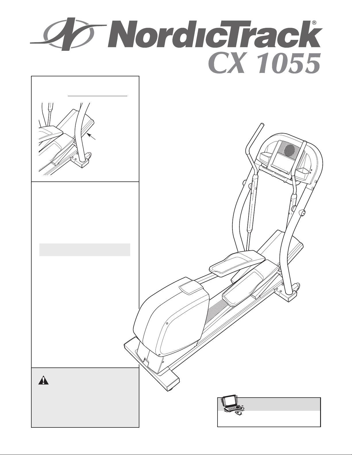
Serial No. _
Serial Number
Decal
(beneath
ramp)
QUESTIONS?
As a manufacturer, we are committed to providing complete
customer satisfaction. If you
have questions, or if there are
missing parts, please call:
1-888-936-4266
USER’S MANUAL
Mon.–Fri. 8h00 until 17h00 EST
(excluding holidays).
CAUTION
Read all precautions and instructions in this manual before using
this equipment. Keep this manual
for future reference.

TABLE OF CONTENTS
IMPORTANT PRECAUTIONS . . . . . . . . . . . . . . . . . . . . . . . . . . . . . . . . . . . . . . . . . . . . . . . . . . . . . . . . . . . . . . . .3
BEFORE YOU BEGIN . . . . . . . . . . . . . . . . . . . . . . . . . . . . . . . . . . . . . . . . . . . . . . . . . . . . . . . . . . . . . . . . . . . . . .4
ASSEMBLY . . . . . . . . . . . . . . . . . . . . . . . . . . . . . . . . . . . . . . . . . . . . . . . . . . . . . . . . . . . . . . . . . . . . . . . . . . . . . . .5
HOW TO USE THE ELLIPTICAL EXERCISER . . . . . . . . . . . . . . . . . . . . . . . . . . . . . . . . . . . . . . . . . . . . . . . . . .10
MAINTENANCE
CONDITIONING GUIDELINES . . . . . . . . . . . . . . . . . . . . . . . . . . . . . . . . . . . . . . . . . . . . . . . . . . . . . . . . . . . . . . .23
PART LIST . . . . . . . . . . . . . . . . . . . . . . . . . . . . . . . . . . . . . . . . . . . . . . . . . . . . . . . . . . . . . . . . . . . . . . . . . . . . . .25
EXPLODED DRAWING . . . . . . . . . . . . . . . . . . . . . . . . . . . . . . . . . . . . . . . . . . . . . . . . . . . . . . . . . . . . . . . . . . . .26
HOW TO ORDER REPLACEMENT PARTS . . . . . . . . . . . . . . . . . . . . . . . . . . . . . . . . . . . . . . . . . . . . .Back Cover
LIMITED WARRANTY . . . . . . . . . . . . . . . . . . . . . . . . . . . . . . . . . . . . . . . . . . . . . . . . . . . . . . . . . . . . . .Back Cover
AND TROUBLESHOOTING . . . . . . . . . . . . . . . . . . . . . . . . . . . . . . . . . . . . . . . . . . . . . . . . . . .22
NordicTrack is a registered trademark of ICON IP, Inc.
2

IMPORTANT PRECAUTIONS
WARNING: T
tions before using the elliptical exerciser.
1. Read all instructions in this manual and all
warnings on the elliptical exerciser before
using the elliptical exerciser.
2. Use the elliptical exerciser only as described
in this manual.
3. It is the responsibility of the owner to ensure
that all users of the elliptical exerciser are
adequately informed of all precautions.
4. The elliptical exerciser is intended for home
use only. Do not use the elliptical exerciser in
a commercial, rental, or institutional setting.
5. Keep the elliptical exerciser indoors, away
from moisture and dust. Place the elliptical
exerciser on a level surface, with a mat
beneath it to protect the floor or carpet.
Make sure that there is enough clearance
around the elliptical exerciser to mount, dismount, and use it.
o reduce the risk of serious injury, read the following important precau-
10.Keep your back straight when using the elliptical exerciser; do not arch your back.
11.If you feel pain or dizziness while exercising,
stop immediately and begin cooling down.
12.Wear appropriate exercise clothes when
using the elliptical exerciser. Always wear
athletic shoes for foot protection.
13.The pulse sensor is not a medical device.
Various factors, including the user's movement, may affect the accuracy of heart rate
readings. The pulse sensor is intended only
as an exercise aid in determining heart rate
trends in general.
14.When you stop exercising, allow the pedals
to slowly come to a complete stop. The elliptical exerciser does not have a free wheel;
the pedals will continue to move until the flywheel stops.
6. Inspect and properly tighten all parts regularly. Replace any worn parts immediately.
7. Keep children under age 12 and pets away
from the elliptical exerciser at all times.
8. The elliptical exerciser should not be used by
persons weighing more than 136 kg (300 lbs.).
9. Always hold the handlebars when mounting,
dismounting, or using the elliptical exerciser.
15.Always unplug the power cord immediately
after use and before cleaning the elliptical
exerciser.
16.The decals shown on page 4 have been
placed on the elliptical exerciser. If either
decal is missing or illegible, please call the
toll-free telephone number on the front cover
of this manual and order a free replacement
decal. Apply the decal in the location shown.
WARNING: Before beginning this or any exercise program, consult your physician.
This is especially important for persons over the age of 35 or persons with pre-existing health problems. Read all instructions before using. ICON assumes no responsibility for personal injury or
property damage sustained by or through the use of this product.
3
BEFORE YOU BEGIN
Congratulations for selecting the new NordicTrack
CX 1055 elliptical exerciser. The CX 1055 elliptical
exerciser is an incredibly smooth exerciser that moves
your feet in a natural elliptical path, minimizing the
impact on your knees and ankles.
1055 elliptical exerciser features adjustable resistance
and incline to help you get the most from your exercise.
For your benefit, read this manual carefully before
you use the elliptical exerciser. If you have ques-
tions after reading this manual, please call the toll-free
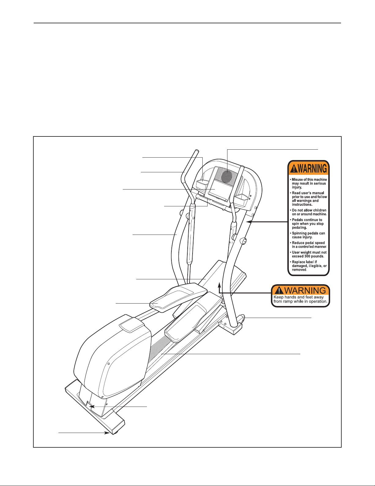
Accessory Tray
Left Handlebar
Console
Handgrip Pulse Sensor
And the unique CX
®
telephone number on the front cover of this manual .
To help us assist you, please note the product model
number and serial number before calling. The model
number is 30508.0. The serial number can be found
on a decal attached to the elliptical exerciser (see the
front cover of this manual for the location of the
decal).
Before reading further, please familiarize yourself with
the parts that are labeled in the drawing below.
Fan
BACK
Left Upright
Incline Ramp
Pedal
Wheel
Pedal Arm
RIGHT SIDE
Power Socket
Foot
4
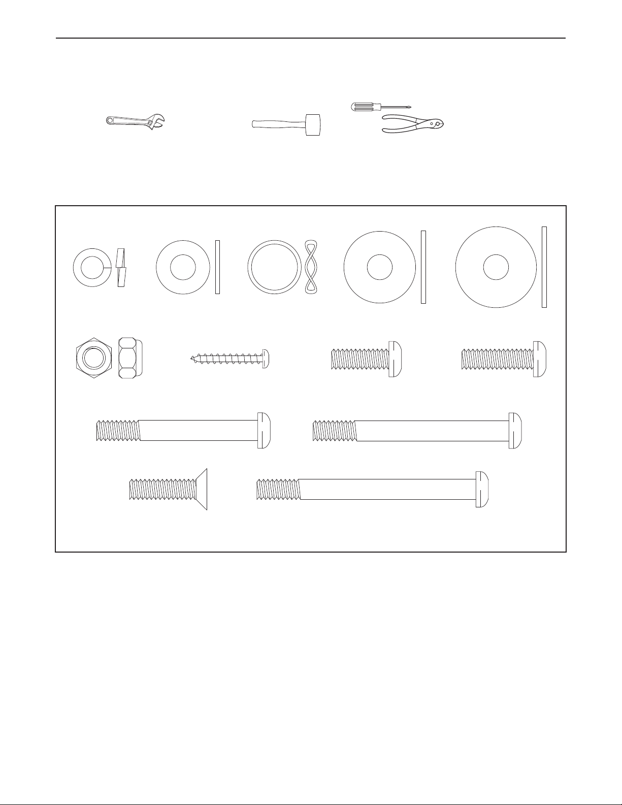
ASSEMBLY
M8 x 68mm Button Screw (110)–8
M8 x 76mm Button Bolt (112)–4
M8 x 23mm Flat
Head Screw (88)–6
M8 Split
Washer
(101)–12
M8 x 28mm
Washer (99)–4
M8 x 25mm
Washer (95)–2
M8 Washer
(94)–6
Wave Washer
(100)–2
M8 Nylon
Locknut (102)–12
M8 x 20mm Button
Screw (113)–2
M8 x 25mm Button
Screw (81)–2
M4 x 25mm
Screw (105)–4
M8 x 56mm Button Screw (108)–4
Assembly requires two persons. Place all parts of the elliptical exerciser in a cleared area and remove the
packing materials. Do not dispose of the packing materials until assembly is completed. In addition to the two
included hex keys, assembly requires a phillips screwdriver
wrenches , a rubber mallet , and pliers .
Use the drawings below to identify the small parts used for assembly. The number in parenthesis below each
drawing is the key number of the part, from the PART LIST on page 25. The number following the key number is
the quantity needed for assembly.
the parts bag, check to see if it has been pre-assembled.
Note: Some small parts may have been pre-assembled. If a part is not in
, two adjustable
5
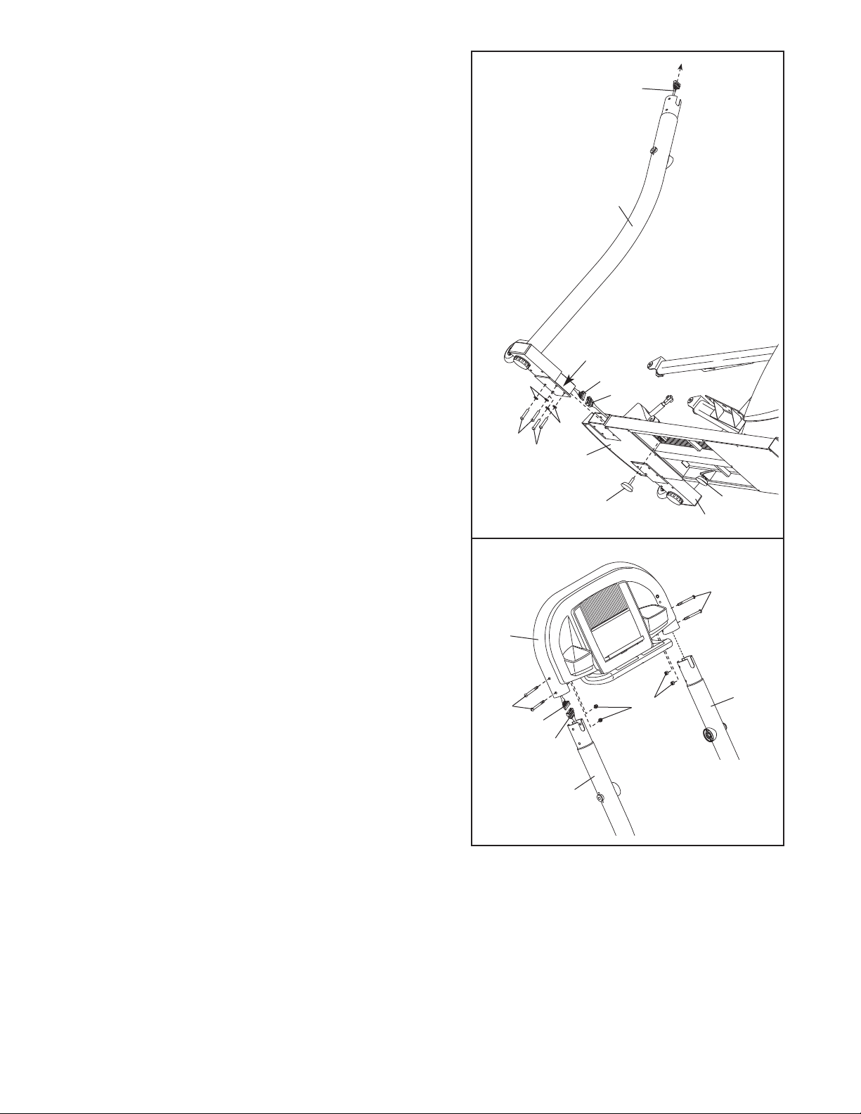
1. Remove the Pivot Arms (not shown) and the plastic
inserts from the Left and Right Uprights (4, 3).
Identify the Left Upright (4) and hold it near the Frame
(1). Connect the Extension W
Lower Wire Harness (77). While another person lifts the
left side of the Frame, pull up on the Extension Wire
Harness and insert the Left Upright into the Frame.
Attach the Left Upright with two M8 x 56mm Button
Screws (108), two M8 x 68mm Button Screws (110),
and four M8 Split Washers (101);
pinching the Wire Harnesses.
ire Harness (76) to the
be careful to avoid
1
Pull
4
Tighten a Frame Cushion (32) into the left side of the
Frame (1) in the indicated location.
While the other person lifts the right side of the Frame
(1), attach the Right Upright (3) in the same way
There are no wire harnesses on the right side.
Tighten the other Frame Cushion (32) into the right
side of the Frame (1).
2. While another person holds the Console Frame (6)
near the Uprights (3, 4), connect the Upper Wire
Harness (75) to the Extension Wire Harness (76).
Push the excess Wire Harness down into the left
Upright. Next, attach the Console Frame to the
Uprights with four M8 x 76mm Button Bolts (112) and
four M8 Nylon Locknuts (102); be careful to avoid
pinching the Wire Harnesses as you slide the
Console Frame onto the Uprights and insert the
Button Bolts.
. Note:
2
108
112
6
101
110
75
76
101
Plastic
Insert
76
1
32
Do not pinch the
wire harnesses
during this step.
77
102
32
3
112
3
4
Do not pinch the
wire harnesses
during this step.
6
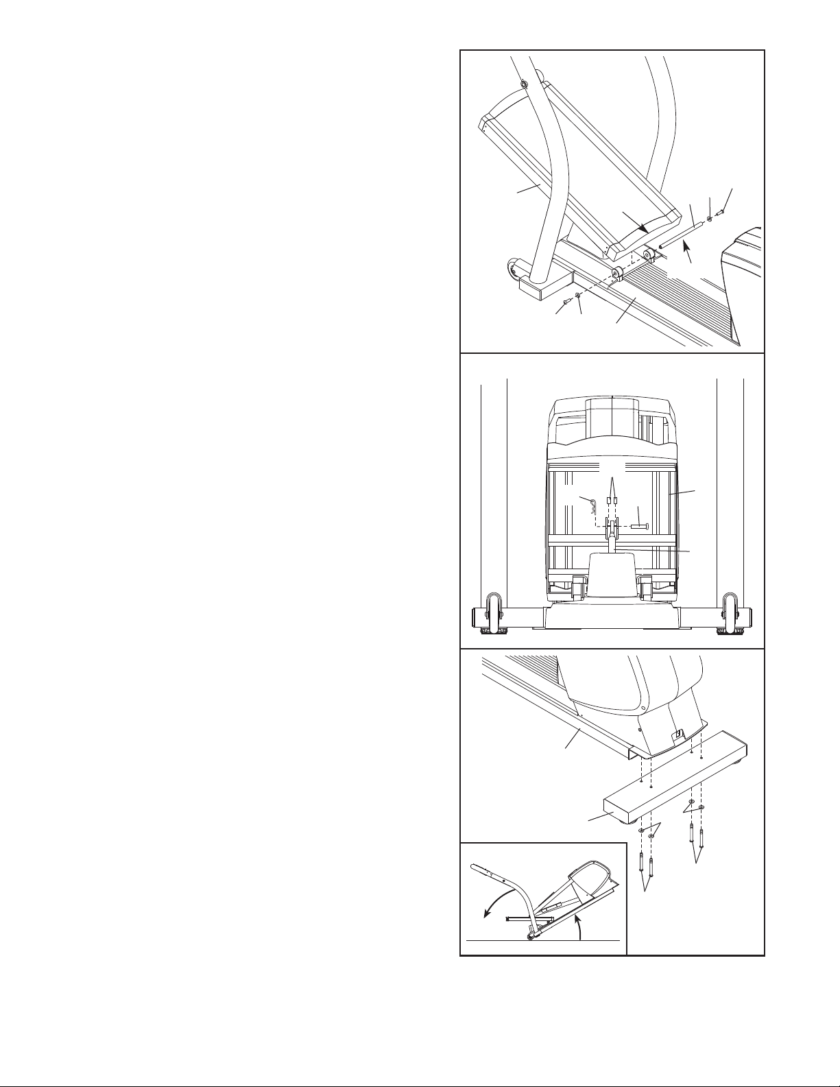
3. Slide an M8 x 28mm Washer (99) onto an M8 x 20mm
Button Screw (113). Tighten the Button Screw into one
end of the Incline
the included grease to the Incline Axle.
Orient the Incline Ramp (5) so that the straight end is
in the position shown. Hold the welded tube on the bottom of the Incline Ramp between the two rings on the
top of the Frame. Insert the Incline Axle (40) through
the rings and the welded tube.
Slide an M8 x 28mm Washer (99) onto an M8 x 20mm
Button Screw (113). Tighten the Button Screw into the
open end of the Incline Axle (40).
Be careful not to scratch the Incline Ramp (5) during
steps 4 through 6.
Axle (40). Apply a small amount of
3
113
5
113
Straight
End
99
1
99
40
Grease
4. Using your fingers, turn the shaft on top of the Lift
Motor (42) counterclockwise until it stops turning.
Position the U-bracket on the bottom of the Incline
Ramp (5) over the end of the shaft as shown. Next,
hold an Incline Motor Spacer (60) on each side of the
shaft, between the shaft and the U-bracket.
Next, insert the Short Clevis Pin (118) through the Ubracket on the Incline Ramp (5), the shaft on the Lift
Motor (42), and the two Incline Motor Spacers (60).
Insert the straight end of a Hairpin (71) into the end of
the Short Clevis Pin.
5. See the inset drawing. While another person tips the
elliptical exerciser as shown, place a sturdy piece of
packaging foam beneath the elliptical exerciser. Have
the other person continue to hold the elliptical
exerciser to steady it during this step.
Orient the Rear Stabilizer (2) so that the holes are
closer to the front. Attach the Rear Stabilizer to the
rear of the Frame (1) with four M8 x 68mm Button
Screws (1
Carefully remove the piece of packaging foam and tip
the elliptical exerciser back down.
10) and four M8 Split W
ashers (101).
4
5
Front View
71
1
2
60
118
5
42
101
110
110
7
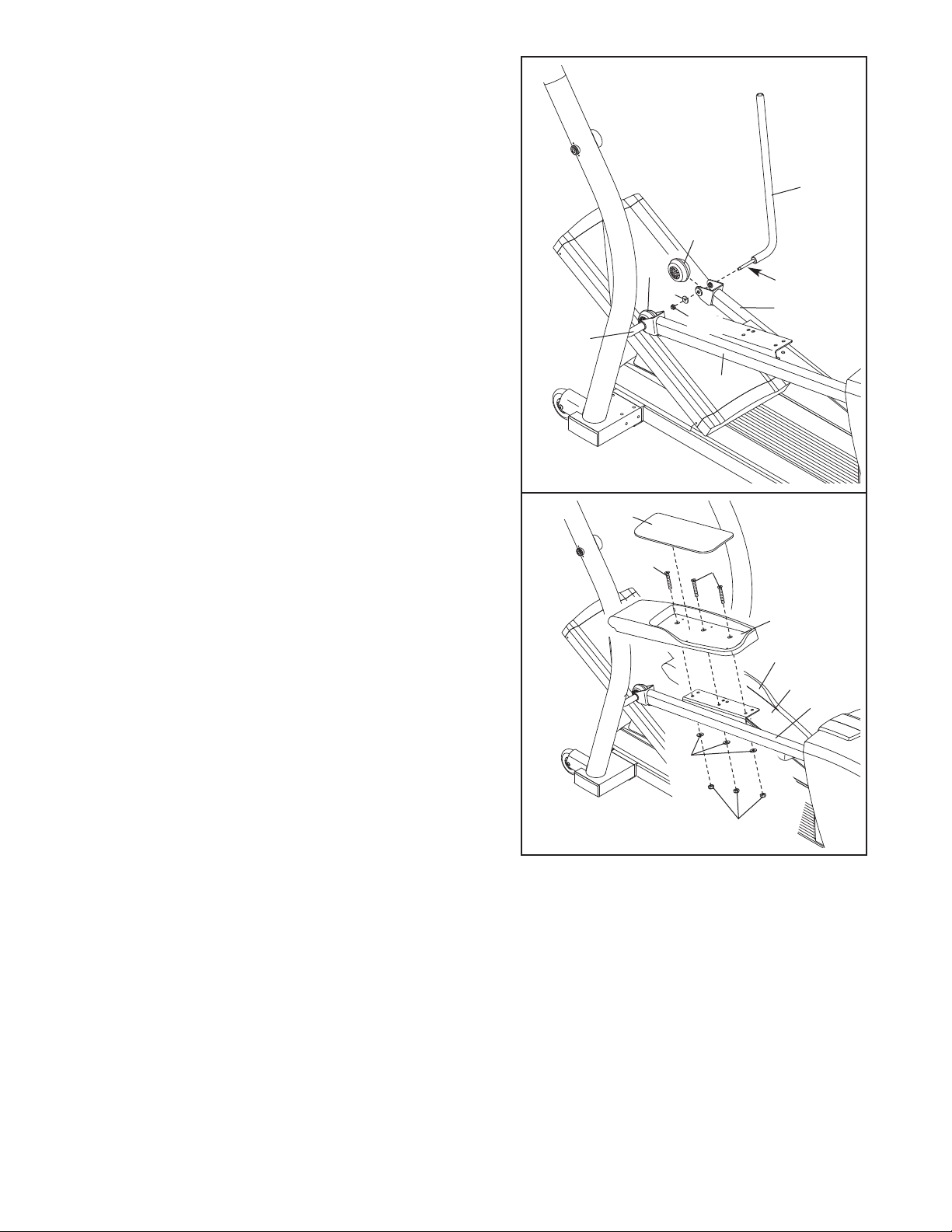
6. Apply a small amount of grease to the axle on each
Pivot Shaft (15).
Hold a Pedal Wheel (35) inside of the bracket on the
end of the Right Pedal
Shaft (15) through the holes in the end of the Right
Pedal Arm and the Pedal Wheel as indicated. Tighten
an M8 Nylon Locknut (102) with an M8 x 25mm
Washer (95) onto the end of the Pivot Shaft.
Attach the other Pivot Shaft (15) and the other Pedal
Wheel (35) to the Left Pedal Arm (12) in the same way.
Arm (11). Next, insert a Pivot
6
15
35
35
95
102
15
12
Grease
11
7. Identify the Left Pedal (14). Attach the Left Pedal to the
Left Pedal Arm (12) with three M8 x 23mm Flat Head
Screws (88), three M8 Washers (94), and three M8
Nylon Locknuts (102). Then, press the Left Pedal
Insert (121) onto the Left Pedal.
Attach the Right Pedal (13) to the Right Pedal Arm (not
shown), and press the Right Pedal Insert (122) into the
Right Pedal, in the same way.
7
121
88
88
14
13
122
12
94
102
8
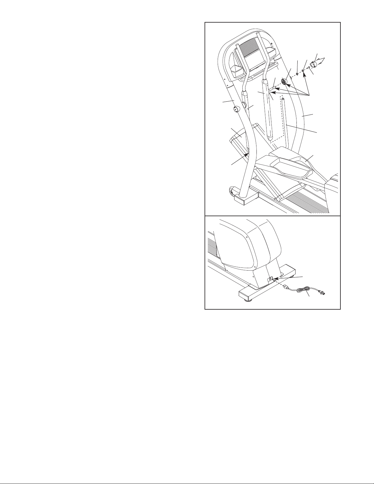
Apply a thin film of the included high-temperature lubri-
8.
cant to both Pivot Shafts (15).
8
Identify the Right Handlebar (9), which is marked with
a sticker. Apply a small amount of grease to the axle
on the Right Handlebar, to the Pivot Arm Cover (64),
and to the Inner Upright Cover (63).
Right Handlebar onto the right Pivot Shaft (15), and
insert the axle on the Right Handlebar into the Right
Upright (3). Note: Position the Right Pedal (13) near
the top of the Incline Ramp (5), and then lift and
push the Pedal toward the center of the Incline
Ramp while inserting the axle into the Upright.
Place a Wave Washer (100) on the end of the axle on
the Right Handlebar (9). Next, apply a small amount of
grease to an M8 x 28mm Washer (99), and slide the
Washer onto an M8 x 25mm Button Screw (81).
Tighten the Button Screw into the axle.
Attach an Outer Upright Cover (74) to the Right
Upright (3) with two M4 x 25mm Screws (105).
Attach the Left Handlebar (10) to the left Pivot Shaft
(15) and the Left Upright (4) in the same way.
9. Plug the Power Cord (8) into the Power Receptical
(68) at the rear of the elliptical exerciser.
Next, slide the
4
Lubricate
9
15
74
99
100
63
Axle
9
10
5
64
105
81
Grease
3
15
Lubricate
13
Next, plug the Power Cord (8) into an appropriate
outlet as described on page 10, and calibrate the
elliptical exerciser’s incline system by following
the steps on page 22.
68
8
10.Make sure that all parts of the elliptical exerciser are properly tightened. Note: Some extra hardware
may be left over.Cover the floor beneath the elliptical exerciser to protect the floor from damage.
9
 Loading...