


I N S T A L L A T I O N & O P E R A T I O N G U I D E
MSU140
INFRARED MAIN SYSTEM UNIT
B L E N D I N G H I G H F I D E L I T Y A N D A R C H I T E C T U R E ®

I N F R A R E D M A I N S Y S T E M U N I T
MSU140
Infrared Main
System Unit
TABLE OF CONTENTS |
Introduction |
||
Introduction |
1 |
An infrared (IR) extender system enables you to control |
|
your IR remote controlled A/V equipment from a remote |
|||
Features and |
|
||
|
location. This enables you to place your A/V components |
||
Benefits |
2 |
||
out of sight (behind cabinet doors, in the rear of a room, or |
|||
MSU140 Parts |
|
||
|
in a different room) and still conveniently operate your |
||
Guide |
4 |
equipment. |
|
Installation |
|
Installed at the equipment location, the MSU140 receives |
|
Considerations |
5 |
the IR commands transmitted from your existing hand- |
|
Installation |
8 |
held remotes in that room. The commands are carried via a |
|
Testing the |
|
small category 5 cable to your A/V equipment in another |
|
IR Extender |
|
room, and instantly “repeated”. |
|
System |
11 |
The MSU140 is compatible with all current Niles infrared |
|
Power Status |
13 |
systems. It may be used along with the Niles TS100, MS100, |
|
Trouble- |
|
MS200, WS100, MVC100IR and CS100 IR sensors or the |
|
Shooting |
15 |
IntelliPad®. |
|
Specifications |
17 |
The model MSU140 is an IR Main System Unit. It is one of |
|
Contents |
17 |
three elements that make up an infrared extender system: |
|
• IR Main System Unit—Models MSU140, MSU250, |
|||
Addendum |
18 |
||
MSU480 and MSU440Z. |
|||
|
|
||
|
|
• IR Sensors/Keypads—Models WS100, TS100, MS100, |
|
|
|
MS200, CS100, IntelliPad, MVC100IR. |
|
|
|
• IR Flashers—Models MF1, MF2, MF1VF, MF2VF. |
|
|
|
An IR sensor expansion hub, Model IRH610, is available to |
|
|
|
provide additional sensor inputs to your system. |
|
|
|
|
|

I N F R A R E D M A I N S Y S T E M U N I T
Features and Benefits
The MSU140 offers a number of improvements over other IR Extender Main System Units:
•Universal system—compatible with virtually all brands of A/V equipment and remote controls.
•Accommodates one IR sensor or keypad.
•Provides four flasher outputs via convenient 3.5mm jacks.
•System feedback LED confirms operation.
•3-30V AC/DC status input. Provides system status to connected sensors and keypads.
•Expandable—an IRH610 IR expansion hub can be used to provide additional inputs.
•Printed circuit board design assures high reliability.
•Low profile and small footprint with integrated mounting wings that allow for both horizontal and vertical installation.
•UL listed regulated in-line power supply with universal voltage capability.
•Two year parts and labor warranty.
2

I N F R A R E D M A I N S Y S T E M U N I T
Niles IR |
Stereo Receiver |
|
Flasher |
||
|
12V DC power supply (supplied with the MSU140 Main System Unit) plugged
into an unswitched AC outlet powers
the system
POWER |
1 |
2 |
3 |
4 |
3-30V |
+12V DC |
|
|
|
|
AC/DC |
|
FLASHER OUTPUTS |
|
STATUS |
||
|
|
|
IN |
||
MSU140
IR MAIN SYSTEM UNIT
INPUT 1
MSU140
3-30V AC/ DC power supply (Not Supplied) plugged into the switched outlet Niles Stock # FG01035
Figure 1
Connecting the WS100 to a Niles MSU140 Main System Unit broadcasting a status feedback signal.
In a typical system, the MSU140 provides for the connection for one remote room sensor (or keypad) and will control multiple audio/video components via its flasher connections.
Power, IR data, status signal and ground via category 5 wire
WS100 IR Sensor
3
I N F R A R E D M A I N S Y S T E M U N I T
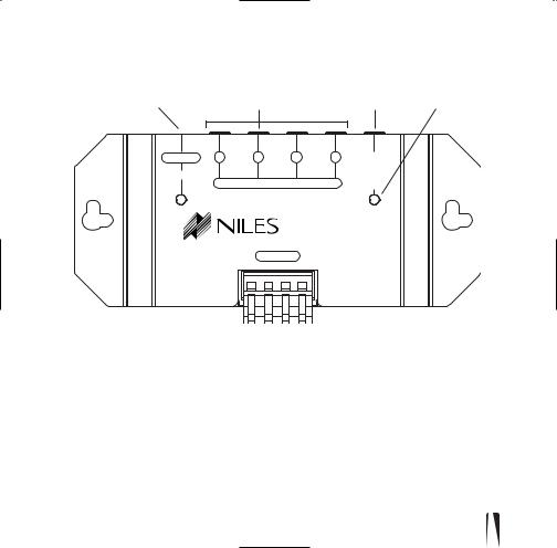
MSU140 Parts Guide
1 |
|
2 |
|
|
3 |
4 |
POWER |
1 |
2 |
3 |
4 |
3-30V |
|
+12V DC |
|
|
|
|
AC/DC |
|
|
FLASHER OUTPUTS |
STATUS |
|
|||
|
|
IN |
|
|||
|
|
|
|
MSU140 |
|
|
|
|
|
IR MAIN SYSTEM UNIT |
|
||
INPUT 1
 5
5
1.12V DC Jack – Provides 12 volt DC power to MSU via a regulated power supply.
2.IR Flasher Outputs – 3.5mm jacks provide output for either single or dual (MF1, MF2, MF1VF, MF2VF) low-level flashers.
3.3-30V AC/DC Status – 3.5mm jack provides system status to sensors/ keypads via a 12 volt power supply attached to a switched outlet on the system receiver or a 12V trigger output.
4.Status/ IR Confirmation LED – This LED performs two functions: (1) it provides a visible indication of system status via a green LED and (2) confirms the reception of IR data via a blinking blue LED.
5.Sensor Input – Removable quick connect sensor plug for connection of IR sensors (WS100, TS100, MS100, MS200, CS100 MVC100IR and the IntelliPad) to the system.
4
I N F R A R E D M A I N S Y S T E M U N I T
|
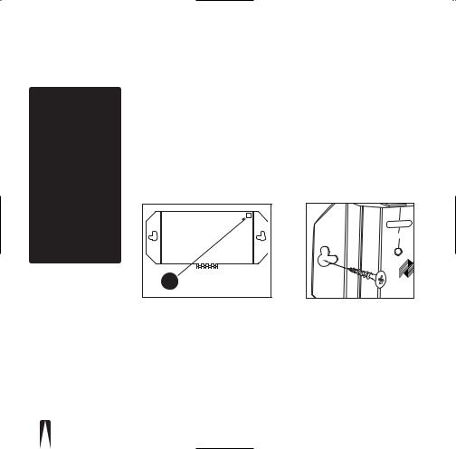
Installation Considerations |
|||
IMPORTANT |
|
|
|
|
Do not place the |
|
|
|
|
MSU140 on top |
|
|
|
|
of or directly |
|
|
|
|
behind a television |
|
|
|
|
set. Some |
|
|
|
|
television sets |
|
|
|
|
produce intense |
|
|
|
|
electromagnetic |
|
|
|
|
interference which |
3-30V |
3 |
2 |
POWER1 |
|
MSU140 |
+12VDC |
||
|
STATUS |
|
|
Base |
may disable |
AC/DC |
|
|
|
IN |
FLASHEROUTPUTS |
|||
your IR extender |
IRMAINSYSTEMUNIT |
|
|
|
|
|
MSU140 |
|
|
system. |
|
INPUT1 |
|
|
|
|
Self-Adhesive |
||
|
|
Rubber Feet |
||
|
Figure 2: Table-top placement |
|||
|
Affix the enclosed self-adhesive |
|||
|
rubber feet to the base of the MSU140. |
|||
equipment it in a conare only
include:
POWER |
+12V DC |
Figure 3: Wall-mount placement
Use sheetrock screws
5
 Loading...