


XS712T Smart Switch
Software Administration Manual
350 East Plumeria Drive
San Jose, CA 95134
USA
March 2013 202-11254-02 v2.0

XS712T Smart Switch
® NETGEAR, Inc. All rights reserved
No part of this publication may be reproduced, transmitted, transcribed, stored in a retrieval system, or translated into any language in any form or by any means without the written permission of NETGEAR, Inc.
Technical Support
Thank you for choosing NETGEAR. To register your product, get the latest product updates, get support online, or for more information about the topics covered in this manual, visit the support website at http://support.netgear.com.
Phone (US & Canada only): 1-888-NETGEAR
Phone (Other Countries): Check the list of phone numbers at
http://support.netgear.com/app/answers/detail/a_id/984.
Trademarks
NETGEAR, the NETGEAR logo, ReadyNAS, ProSafe, ProSecure, Smart Control Center, Auto Uplink, X-RAID2, and NeoTV are trademarks or registered trademarks of NETGEAR, Inc. Microsoft, Windows, Windows NT, and Vista are registered trademarks of Microsoft Corporation. Other brand and product names are registered trademarks or trademarks of their respective holders.
Statement of Conditions
To improve internal design, operational function, and/or reliability, NETGEAR reserves the right to make changes to the products described in this document without notice. NETGEAR does not assume any liability that may occur due to the use, or application of, the product(s) or circuit layout(s) described herein.
Revision History
Publication Part Number |
Version |
Publish Date |
Comments |
|
|
|
|
202-11254-02 |
v2.0 |
April 2013 |
Minor text edits. |
|
|
|
|
202-11254-01 |
v1.0 |
March 2013 |
First publication |
|
|
|
|
2

Contents
Chapter 1 Getting Started
Getting Started with the XS712T Smart Switch. . . . . . . . . . . . . . . . . . . . . . 7 Connect the Switch to the Network . . . . . . . . . . . . . . . . . . . . . . . . . . . . . . . 8 Discover a Switch in a Network with a DHCP Server . . . . . . . . . . . . . . . . . 9 Discover a Switch in a Network without a DHCP Server. . . . . . . . . . . . . . 10 Configure the Network Settings on the Administrative System . . . . . . . . . 12 Access the Management Interface from a Web Browser . . . . . . . . . . . . . 15 Understand the User Interfaces. . . . . . . . . . . . . . . . . . . . . . . . . . . . . . . . . 16
Use the Web Interface . . . . . . . . . . . . . . . . . . . . . . . . . . . . . . . . . . . . . . 16 Use SNMPv3 . . . . . . . . . . . . . . . . . . . . . . . . . . . . . . . . . . . . . . . . . . . . . 21 Support . . . . . . . . . . . . . . . . . . . . . . . . . . . . . . . . . . . . . . . . . . . . . . . . . 24 User Guide. . . . . . . . . . . . . . . . . . . . . . . . . . . . . . . . . . . . . . . . . . . . . . . 24
Chapter 2 Configure System Information
Management . . . . . . . . . . . . . . . . . . . . . . . . . . . . . . . . . . . . . . . . . . . . . . . 26
IPv6 Network Neighbor . . . . . . . . . . . . . . . . . . . . . . . . . . . . . . . . . . . . . 32
Time. . . . . . . . . . . . . . . . . . . . . . . . . . . . . . . . . . . . . . . . . . . . . . . . . . . . 33
Denial of Service . . . . . . . . . . . . . . . . . . . . . . . . . . . . . . . . . . . . . . . . . . 40
Green Ethernet . . . . . . . . . . . . . . . . . . . . . . . . . . . . . . . . . . . . . . . . . . . 46
SNMPV1/V2. . . . . . . . . . . . . . . . . . . . . . . . . . . . . . . . . . . . . . . . . . . . . . 53
LLDP-MED Network Policy . . . . . . . . . . . . . . . . . . . . . . . . . . . . . . . . . . 60
LLDP-MED Port Settings . . . . . . . . . . . . . . . . . . . . . . . . . . . . . . . . . . . . 61
Local Information . . . . . . . . . . . . . . . . . . . . . . . . . . . . . . . . . . . . . . . . . . 62
Neighbors Information . . . . . . . . . . . . . . . . . . . . . . . . . . . . . . . . . . . . . . 65
Services—DHCP Snooping. . . . . . . . . . . . . . . . . . . . . . . . . . . . . . . . . . . . 69
Chapter 3 Layer 2 Switching Configuration
Ports . . . . . . . . . . . . . . . . . . . . . . . . . . . . . . . . . . . . . . . . . . . . . . . . . . . . . 77
Port Configuration . . . . . . . . . . . . . . . . . . . . . . . . . . . . . . . . . . . . . . . . . 77
Flow Control. . . . . . . . . . . . . . . . . . . . . . . . . . . . . . . . . . . . . . . . . . . . . . 79
LAG Configuration . . . . . . . . . . . . . . . . . . . . . . . . . . . . . . . . . . . . . . . . . 80
LAG Membership. . . . . . . . . . . . . . . . . . . . . . . . . . . . . . . . . . . . . . . . . . 81
LACP Configuration . . . . . . . . . . . . . . . . . . . . . . . . . . . . . . . . . . . . . . . . 82
VLANs . . . . . . . . . . . . . . . . . . . . . . . . . . . . . . . . . . . . . . . . . . . . . . . . . . . . 84
VLAN Membership Configuration . . . . . . . . . . . . . . . . . . . . . . . . . . . . . 86
VLAN Status . . . . . . . . . . . . . . . . . . . . . . . . . . . . . . . . . . . . . . . . . . . . . 87
Port VLAN ID Configuration. . . . . . . . . . . . . . . . . . . . . . . . . . . . . . . . . . 87
MAC Based VLAN . . . . . . . . . . . . . . . . . . . . . . . . . . . . . . . . . . . . . . . . . 89
Table of Contents | 3

XS712T Smart Switch
Protocol Based VLAN Group Configuration . . . . . . . . . . . . . . . . . . . . . . 90
Protocol Based VLAN Group Membership . . . . . . . . . . . . . . . . . . . . . . . 91
Auto-VoIP Configuration. . . . . . . . . . . . . . . . . . . . . . . . . . . . . . . . . . . . . . . 93
Configure Protocol-Based Auto VoIP Settings . . . . . . . . . . . . . . . . . . . . 93
Port Settings. . . . . . . . . . . . . . . . . . . . . . . . . . . . . . . . . . . . . . . . . . . . . . 95
OUI Table . . . . . . . . . . . . . . . . . . . . . . . . . . . . . . . . . . . . . . . . . . . . . . . . 96
CST Port Configuration . . . . . . . . . . . . . . . . . . . . . . . . . . . . . . . . . . . . 102
Rapid STP . . . . . . . . . . . . . . . . . . . . . . . . . . . . . . . . . . . . . . . . . . . . . . 105
MST Configuration . . . . . . . . . . . . . . . . . . . . . . . . . . . . . . . . . . . . . . . . 106
MST Port Configuration . . . . . . . . . . . . . . . . . . . . . . . . . . . . . . . . . . . . 107
STP Statistics . . . . . . . . . . . . . . . . . . . . . . . . . . . . . . . . . . . . . . . . . . . . 109
Bridge Multicast Forwarding . . . . . . . . . . . . . . . . . . . . . . . . . . . . . . . . . 111
MFDB Table . . . . . . . . . . . . . . . . . . . . . . . . . . . . . . . . . . . . . . . . . . . . . 112
IGMP Snooping . . . . . . . . . . . . . . . . . . . . . . . . . . . . . . . . . . . . . . . . . . 114
IGMP Snooping Querier . . . . . . . . . . . . . . . . . . . . . . . . . . . . . . . . . . . . 121
MLD Snooping . . . . . . . . . . . . . . . . . . . . . . . . . . . . . . . . . . . . . . . . . . . 124
Forwarding Database . . . . . . . . . . . . . . . . . . . . . . . . . . . . . . . . . . . . . . . . 132
MAC Address Table . . . . . . . . . . . . . . . . . . . . . . . . . . . . . . . . . . . . . . . 132
Dynamic Address Configuration . . . . . . . . . . . . . . . . . . . . . . . . . . . . . . 133
Address Table . . . . . . . . . . . . . . . . . . . . . . . . . . . . . . . . . . . . . . . . . . . 134
Static MAC Address . . . . . . . . . . . . . . . . . . . . . . . . . . . . . . . . . . . . . . . 135
Chapter 4 Configuring Routing
Configure IP Settings . . . . . . . . . . . . . . . . . . . . . . . . . . . . . . . . . . . . . . . . 137
IP Statistics. . . . . . . . . . . . . . . . . . . . . . . . . . . . . . . . . . . . . . . . . . . . . . 138
Configure VLAN Routing . . . . . . . . . . . . . . . . . . . . . . . . . . . . . . . . . . . . . 142
VLAN Routing Wizard. . . . . . . . . . . . . . . . . . . . . . . . . . . . . . . . . . . . . . 142
Router Discovery Configuration . . . . . . . . . . . . . . . . . . . . . . . . . . . . . . 145
Configure and View Routes . . . . . . . . . . . . . . . . . . . . . . . . . . . . . . . . . . . 146
Configure ARP . . . . . . . . . . . . . . . . . . . . . . . . . . . . . . . . . . . . . . . . . . . . . 148
ARP Cache. . . . . . . . . . . . . . . . . . . . . . . . . . . . . . . . . . . . . . . . . . . . . . 148
Create a Static ARP Entry . . . . . . . . . . . . . . . . . . . . . . . . . . . . . . . . . . 149
Configure Global ARP Settings . . . . . . . . . . . . . . . . . . . . . . . . . . . . . . 150
Chapter 5 Configuring Quality of Service
Class of Service . . . . . . . . . . . . . . . . . . . . . . . . . . . . . . . . . . . . . . . . . . . . 153 Basic CoS Configuration . . . . . . . . . . . . . . . . . . . . . . . . . . . . . . . . . . . 154 CoS Interface Configuration . . . . . . . . . . . . . . . . . . . . . . . . . . . . . . . . . 155 Interface Queue Configuration . . . . . . . . . . . . . . . . . . . . . . . . . . . . . . . 156 802.1p to Queue Mapping . . . . . . . . . . . . . . . . . . . . . . . . . . . . . . . . . . 158 DSCP to Queue Mapping . . . . . . . . . . . . . . . . . . . . . . . . . . . . . . . . . . . 159
Differentiated Services . . . . . . . . . . . . . . . . . . . . . . . . . . . . . . . . . . . . . . . 160 Defining DiffServ. . . . . . . . . . . . . . . . . . . . . . . . . . . . . . . . . . . . . . . . . . 160 Class Configuration . . . . . . . . . . . . . . . . . . . . . . . . . . . . . . . . . . . . . . . 162 Policy Configuration . . . . . . . . . . . . . . . . . . . . . . . . . . . . . . . . . . . . . . . 166 Service Configuration . . . . . . . . . . . . . . . . . . . . . . . . . . . . . . . . . . . . . . 169 Service Statistics . . . . . . . . . . . . . . . . . . . . . . . . . . . . . . . . . . . . . . . . . 170
4

XS712T Smart Switch
Chapter 6 Managing Device Security
Management Security Settings. . . . . . . . . . . . . . . . . . . . . . . . . . . . . . . . .171
Change Password . . . . . . . . . . . . . . . . . . . . . . . . . . . . . . . . . . . . . . . .171
Authentication List Configuration . . . . . . . . . . . . . . . . . . . . . . . . . . . . .180
Configure Management Access . . . . . . . . . . . . . . . . . . . . . . . . . . . . . . . .183
HTTP Configuration . . . . . . . . . . . . . . . . . . . . . . . . . . . . . . . . . . . . . . .183
Secure HTTP Configuration . . . . . . . . . . . . . . . . . . . . . . . . . . . . . . . . .184
Certificate Management . . . . . . . . . . . . . . . . . . . . . . . . . . . . . . . . . . . .185
Certificate Download. . . . . . . . . . . . . . . . . . . . . . . . . . . . . . . . . . . . . . .186
802.1X Configuration . . . . . . . . . . . . . . . . . . . . . . . . . . . . . . . . . . . . . .190
Port Authentication . . . . . . . . . . . . . . . . . . . . . . . . . . . . . . . . . . . . . . . .191
Port Summary. . . . . . . . . . . . . . . . . . . . . . . . . . . . . . . . . . . . . . . . . . . .195
Traffic Control . . . . . . . . . . . . . . . . . . . . . . . . . . . . . . . . . . . . . . . . . . . . . .197
MAC Filter Configuration . . . . . . . . . . . . . . . . . . . . . . . . . . . . . . . . . . .197
MAC Filter Summary . . . . . . . . . . . . . . . . . . . . . . . . . . . . . . . . . . . . . .199
Port Security Configuration. . . . . . . . . . . . . . . . . . . . . . . . . . . . . . . . . .201
Port Security Interface Configuration . . . . . . . . . . . . . . . . . . . . . . . . . .202
Security MAC Address . . . . . . . . . . . . . . . . . . . . . . . . . . . . . . . . . . . . .204
Private VLAN Configuration . . . . . . . . . . . . . . . . . . . . . . . . . . . . . . . . .205
Private VLAN Association Configuration . . . . . . . . . . . . . . . . . . . . . . .206
Private VLAN Port Mode Configuration . . . . . . . . . . . . . . . . . . . . . . . .207
Private VLAN Host Interface Configuration . . . . . . . . . . . . . . . . . . . . .208
Private VLAN Promiscuous Interface Configuration . . . . . . . . . . . . . . .210
MAC Rules . . . . . . . . . . . . . . . . . . . . . . . . . . . . . . . . . . . . . . . . . . . . . .216
MAC Binding Configuration . . . . . . . . . . . . . . . . . . . . . . . . . . . . . . . . .218
MAC Binding Table. . . . . . . . . . . . . . . . . . . . . . . . . . . . . . . . . . . . . . . .219
IP ACL . . . . . . . . . . . . . . . . . . . . . . . . . . . . . . . . . . . . . . . . . . . . . . . . .220
IP Rules . . . . . . . . . . . . . . . . . . . . . . . . . . . . . . . . . . . . . . . . . . . . . . . .221
IP Extended Rules . . . . . . . . . . . . . . . . . . . . . . . . . . . . . . . . . . . . . . . .222
IPv6 ACL. . . . . . . . . . . . . . . . . . . . . . . . . . . . . . . . . . . . . . . . . . . . . . . .225
IPv6 Rules . . . . . . . . . . . . . . . . . . . . . . . . . . . . . . . . . . . . . . . . . . . . . .226
Chapter 7 Monitoring the System
Ports . . . . . . . . . . . . . . . . . . . . . . . . . . . . . . . . . . . . . . . . . . . . . . . . . . . . .233
Switch Statistics . . . . . . . . . . . . . . . . . . . . . . . . . . . . . . . . . . . . . . . . . .233
Port Statistics . . . . . . . . . . . . . . . . . . . . . . . . . . . . . . . . . . . . . . . . . . . .236
Logs . . . . . . . . . . . . . . . . . . . . . . . . . . . . . . . . . . . . . . . . . . . . . . . . . . . . .248
FLASH Log . . . . . . . . . . . . . . . . . . . . . . . . . . . . . . . . . . . . . . . . . . . . . .250
Mirroring . . . . . . . . . . . . . . . . . . . . . . . . . . . . . . . . . . . . . . . . . . . . . . . . . .256
Chapter 8 Maintenance
Reset . . . . . . . . . . . . . . . . . . . . . . . . . . . . . . . . . . . . . . . . . . . . . . . . . . . .259
Device Reboot . . . . . . . . . . . . . . . . . . . . . . . . . . . . . . . . . . . . . . . . . . .259
Factory Default . . . . . . . . . . . . . . . . . . . . . . . . . . . . . . . . . . . . . . . . . . .260
Upload . . . . . . . . . . . . . . . . . . . . . . . . . . . . . . . . . . . . . . . . . . . . . . . . . . .260
HTTP File Upload . . . . . . . . . . . . . . . . . . . . . . . . . . . . . . . . . . . . . . . . .262
5

XS712T Smart Switch
Download . . . . . . . . . . . . . . . . . . . . . . . . . . . . . . . . . . . . . . . . . . . . . . . . . 263
TFTP File Download. . . . . . . . . . . . . . . . . . . . . . . . . . . . . . . . . . . . . . . 263
HTTP File Download . . . . . . . . . . . . . . . . . . . . . . . . . . . . . . . . . . . . . . 265
File Management . . . . . . . . . . . . . . . . . . . . . . . . . . . . . . . . . . . . . . . . . . . 266
Copy . . . . . . . . . . . . . . . . . . . . . . . . . . . . . . . . . . . . . . . . . . . . . . . . . . . 266
Dual Image Configuration. . . . . . . . . . . . . . . . . . . . . . . . . . . . . . . . . . . 267
Appendix A Smart Control Center Utilities
Network Utilities . . . . . . . . . . . . . . . . . . . . . . . . . . . . . . . . . . . . . . . . . . . . 269
Upload and Download the Configuration . . . . . . . . . . . . . . . . . . . . . . . 273
Appendix B Troubleshooting
Troubleshooting Configuration Menu . . . . . . . . . . . . . . . . . . . . . . . . . . . . 279
Ping . . . . . . . . . . . . . . . . . . . . . . . . . . . . . . . . . . . . . . . . . . . . . . . . . . . 279
Troubleshooting Chart . . . . . . . . . . . . . . . . . . . . . . . . . . . . . . . . . . . . . . . 283
Appendix C Configuration Examples
Virtual Local Area Networks (VLANs) . . . . . . . . . . . . . . . . . . . . . . . . . . . 285 Sample VLAN Configuration. . . . . . . . . . . . . . . . . . . . . . . . . . . . . . . . . 286 Access Control Lists (ACLs). . . . . . . . . . . . . . . . . . . . . . . . . . . . . . . . . . . 287 MAC ACL Example Configuration . . . . . . . . . . . . . . . . . . . . . . . . . . . . 288 Sample Standard IP ACL Configuration. . . . . . . . . . . . . . . . . . . . . . . . 289 Differentiated Services (DiffServ) . . . . . . . . . . . . . . . . . . . . . . . . . . . . . . . 290 DiffServ Traffic Classes . . . . . . . . . . . . . . . . . . . . . . . . . . . . . . . . . . . . 291 Sample DiffServ Configuration . . . . . . . . . . . . . . . . . . . . . . . . . . . . . . . 293 802.1X . . . . . . . . . . . . . . . . . . . . . . . . . . . . . . . . . . . . . . . . . . . . . . . . . . . 294 Sample 802.1X Configuration. . . . . . . . . . . . . . . . . . . . . . . . . . . . . . . . 296 MSTP . . . . . . . . . . . . . . . . . . . . . . . . . . . . . . . . . . . . . . . . . . . . . . . . . . . . 297 VLAN Routing Overview. . . . . . . . . . . . . . . . . . . . . . . . . . . . . . . . . . . . 301 Sample VLAN Routing Configuration . . . . . . . . . . . . . . . . . . . . . . . . . . 301
Appendix D Hardware Specifications and Default Values
XS712T Smart Switch Specifications . . . . . . . . . . . . . . . . . . . . . . . . . . . . 303
XS712T Switch Features and Defaults . . . . . . . . . . . . . . . . . . . . . . . . . . 304
Appendix E Notification of Compliance
6

1. Getting Started |
1 |
|
|
||
|
|
|
This manual describes how to configure and operate the XS712T Smart Switch by using the web-based graphical user interface (GUI). The manual describes the software configuration procedures and explains the options available within those procedures.
Note: For information about issues and workarounds, see the release notes for the XS712T Smart Switch.
Getting Started with the XS712T Smart Switch
This chapter provides an overview of starting your NETGEAR XS712T Smart Switch and accessing the user interface. It also leads you through the steps to use the Smart Control Center utility. This chapter contains the following sections:
•Switch Management Interface
•Connect the Switch to the Network
•Discover a Switch in a Network with a DHCP Server
•Discover a Switch in a Network without a DHCP Server
•Configure the Network Settings on the Administrative System
•Access the Management Interface from a Web Browser
•Understand the User Interfaces
•Interface Naming Convention
•Online Help
•Registration
7

XS712T Smart Switch
Switch Management Interface
The NETGEAR XS712T Smart Switch contain an embedded web server and management software for managing and monitoring switch functions. The XS712T functions as a simple switch without the management software. However, you can use the management software to configure more advanced features that can improve switch efficiency and overall network performance.
Web-based management lets you monitor, configure, and control your switch remotely using a standard web browser instead of using expensive and complicated SNMP software products. From your web browser, you can monitor the performance of your switch and optimize its configuration for your network. You can configure all switch features, such as VLANs, QoS, and ACLs, by using the web management interface.
NETGEAR provides the Smart Control Center utility with this product. This program runs under Microsoft Windows XP, Windows 2000, or Windows Vista and provides a front end that discovers the switches on your network segment (L2 broadcast domain). When you power up your switch for the first time, use the Smart Control Center to discover the switch and view the network information that has been automatically assigned to the switch by a DHCP server; or, if no DHCP server is present on the network, use the Smart Control Center to discover the switch and assign static network information.
In addition to enabling NETGEAR switch discovery, the Smart Control Center provides several utilities to help you maintain the NETGEAR switches on your network, such as password management, firmware upgrade, and configuration file backup. For more information, see Appendix A, Smart Control Center Utilities.
Connect the Switch to the Network
To enable remote management of the switch through a web browser or SNMP, you must connect the switch to the network and configure it with network information (an IP address, subnet mask, and default gateway). The switch has a default IP address of 192.168.0.239 and a default subnet mask of 255.255.255.0.
To change the default network information on the switch, use one of the following three methods:
•Dynamic assignment through DHCP. DHCP is enabled by default on the switch. If you connect the switch to a network with a DHCP server, the switch obtains its network information automatically. You can use the Smart Control Center to discover the automatically assigned network information. For more information, see Discover a Switch in a Network with a DHCP Server on page 9.
•Static assignment through the Smart Control Center. If you connect the switch to a network that does not have a DHCP server, you can use the Smart Control Center to assign a static IP address, subnet mask, and default gateway. For more information, see
Discover a Switch in a Network without a DHCP Server on page 10.
•Static assignment by connecting from a local host. If you do not want to use the Smart Control Center to assign a static address, you can connect to the switch from a
8
XS712T Smart Switch
host (administrative system) in the 192.168.0.0/24 network and change the settings by using the web management interface on the switch. For information about how to set the IP address on the administrative system so it is in the same subnet as the default IP address of the switch, see Configure the Network Settings on the Administrative System on page 12.
Discover a Switch in a Network with a DHCP Server
This section describes how to set up your switch in a network that has a DHCP server. The DHCP client on the switch is enabled by default. When you connect it to your network, the DHCP server will automatically assign an IP address to your switch. Use the Smart Control Center to discover the IP address automatically assigned to the switch.
To install the switch in a network with a DHCP server:
1.Connect the switch to a network with a DHCP server.
2.Power on the switch by connecting its power cord.
3.Install the Smart Control Center on your computer.
4.Start the Smart Control Center.
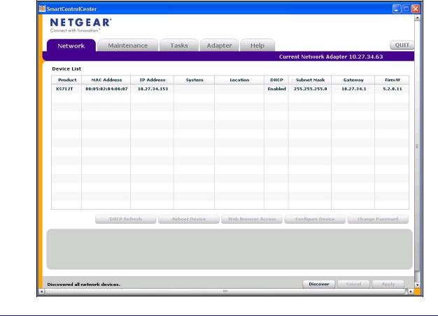
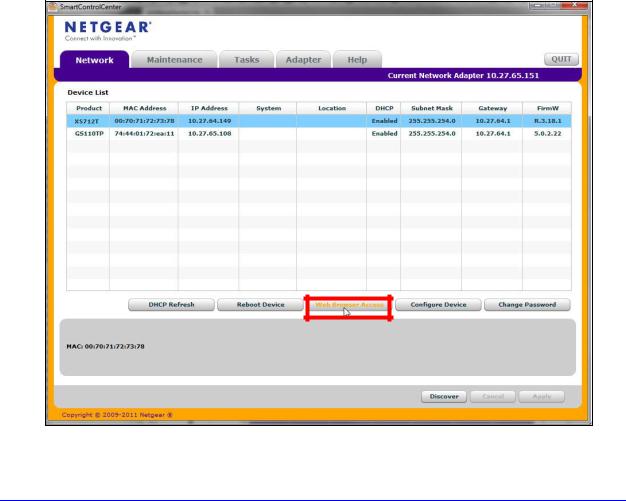
5.Click Discover for the Smart Control Center to find your switch.
A screen similar to the one shown in the following figure displays.
9
XS712T Smart Switch
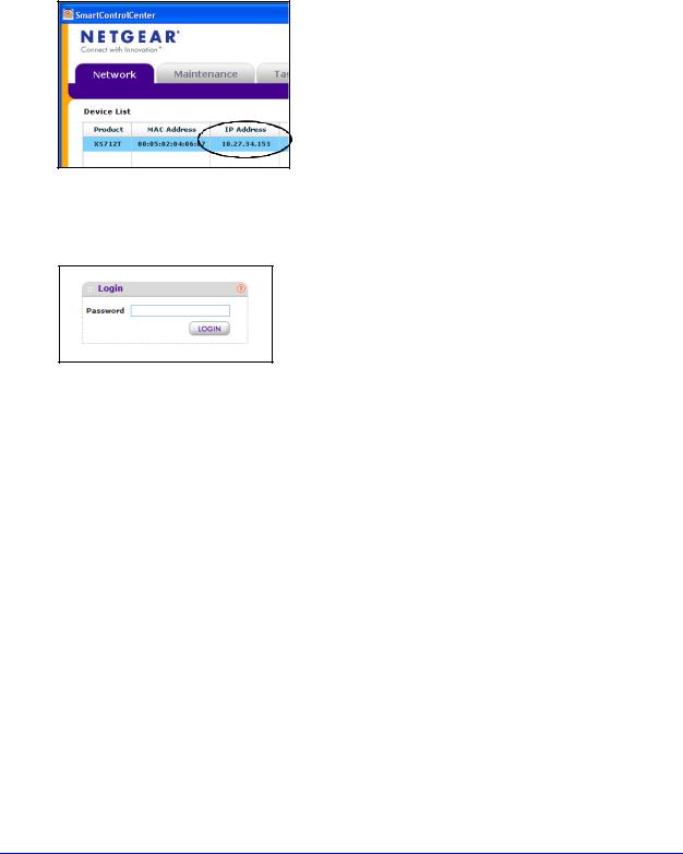
6.Make a note of the displayed IP address assigned by the DHCP server.
You will need this value to access the switch directly from a web browser (without using the Smart Control Center).
7.Select your switch by clicking the line that displays the switch, then click the
Web Browser Access button.
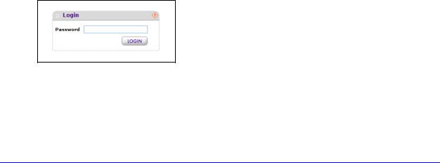
The Smart Control Center displays a login window.
Use your web browser to manage your switch. The default password is password. Use this screen to manage your switch. For more information, see Use the Web Interface on page 16.
Discover a Switch in a Network without a DHCP Server
This section describes how to use the Smart Control Center to set up your switch in a network without a DHCP server. If your network has no DHCP service, you must assign a static IP address to your switch. If you choose, you can assign it a static IP address, even if your network has DHCP service.
To assign a static IP address:
1.Connect the switch to your existing network.
2.Power on the switch by connecting its power cord.
3.Install the Smart Control Center on your computer.
4.Start the Smart Control Center.
5.Click Discover for the Smart Control Center to find your XS712T switch.
The utility broadcasts Layer 2 discovery packets within the broadcast domain to discover the switch.
10
XS712T Smart Switch
6.Select the switch, then click Configure Device.
The screen expands to display additional fields at the bottom.
7.Select the Disabled radio button to disable DHCP.
8.Enter the static switch IP address, gateway IP address, and subnet mask for the switch, and then type your password.
Tip: You must enter the current password every time you use the Smart Control Center to update the switch setting. The default password is password.
9. Click Apply to configure the switch with the network settings.
Ensure that your computer and the switch are in the same subnet. Make a note of these settings for later use.
11
XS712T Smart Switch
Configure the Network Settings on the Administrative System
If you choose not to use the Smart Control Center to configure the network information on the switch, you can connect directly to the switch from an administrative system, such as a computer or laptop. The IP address of the administrative system must be in the same subnet as the default IP address on the switch. For most networks, this means you must change the IP address of the administrative system to be on the same subnet as the default IP address of the switch (192.168.0.239).
The method to change the IP address on an administrative system varies depending on the operating system version. You need Windows Administrator privileges to change these settings. The following procedures show how to change the static IP address on a computer running a Microsoft Windows 7.
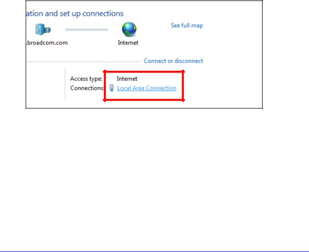
To modify the network settings on your administrative system:
1.Open the Control Panel and click Network and Sharing Center.
2.Click the Local Area Connection link.
12

XS712T Smart Switch
3.In the Local Area Connection Status window, click Properties. The Local Area Connection Properties window displays.
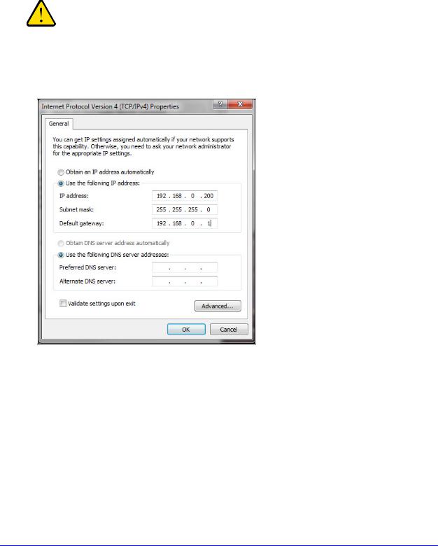
4.Select the Internet Protocol Version 4 (TCP/IPv4) option, and then click Properties. The Internet Protocol Version 4 (TCP/IPv4) Properties window displays.
13
XS712T Smart Switch
5.Select Use the following IP address and set the IP address of the administrative system to an address in the 192.168.0.0 network, such as 192.168.0.200.
The IP address must be different from that of the switch but within the same subnet.
WARNING:
When you change the IP address of your administrative system, you lose your connection to the rest of the network. Be sure to write down your current network address settings before you change them.
6.Click OK.
To configure a static address on the switch:
1.Use a straight-through cable to connect the Ethernet port on the administrative system directly to any port on the XS712T.
2.Open a web browser on your computer and connect to the management interface.
For more information, see Access the Management Interface from a Web Browser on page 15.
3.Change the network settings on the switch to match those of your network. For more information, see IP Configuration on page 29.
After you change the network settings on the switch, return the network configuration on your administrative system to the original settings.
14
XS712T Smart Switch
Access the Management Interface from a Web Browser
You must be able to ping the IP address of the switch web management interface from your administrative system for web access to be available. If you used the Smart Control Center to set up the IP address and subnet mask, either with or without a DHCP server, use that IP address in the address field of your web browser. If you did not change the IP address of the switch from the default value, enter 192.168.0.239 in the address field.
To access the switch management interface, use one of the following methods:
•From the Smart Control Center, select the switch and click Web Browser Access.
•Open a web browser and enter the IP address of the switch in the address field.
To access the management interface from a web browser: 1. Open a web browser.
The utility discovers all switches in the same Layer 2 domain as the administrative system.
2.Select the switch to access.
3.Click Web Browser Access.
A web browser launches and opens to the switch Login screen.
15
XS712T Smart Switch
To access the management interface form the Smart Control Center:
1.Open a web browser.
2.Enter the IP address of the switch in the address field of the browser.
Understand the User Interfaces
The XS712T Smart Switch software includes a set of comprehensive management functions for configuring and monitoring the system by using one of the following methods:
•Web user interface
•Simple Network Management Protocol (SNMP)
Each of the standards-based management methods allows you to configure and monitor the components of the XS712T Smart Switch software. The method you use to manage the system depends on your network size and requirements, and on your preference.
This manual describes how to use the web-based interface to manage and monitor the system.
Use the Web Interface
To access the switch by using a web browser, the browser must meet the following software requirements:
•HTML version 4.0, or later
•HTTP version 1.1, or later
•Java Runtime Environment 1.6 or later
To log on to the Web interface:
1. Open a web browser and enter the IP address of the switch in the web browser address field.
The login screen displays.
2.Type the password in the Password field.
The factory default password is password. Passwords are case-sensitive.
3.Click Login.
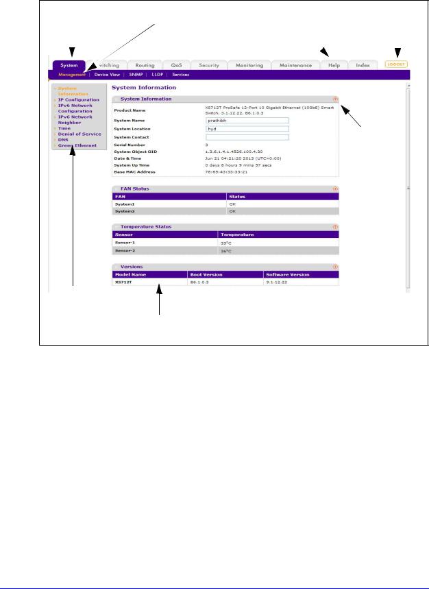
After the system authenticates you, the System Information screen displays. The following figure shows the layout of the Smart Switch web interface.
16
XS712T Smart Switch
Navigation tab |
Configuration menus |
Help link |
||
|
|
|
Logout button |
|
|
|
|
||
|
|
|
|
|
|
|
|
|
|
Help
page
Links
Configuration status and options
Figure 1. Smart Switch Web Interface
Navigation Tabs, Configuration Menus, and Links
The navigation tabs along the top of the web interface give you quick access to the various switch functions. The tabs are always available and remain constant, regardless of which feature you configure.
When you select a tab, the features for that tab appear as links directly under the tabs. The configuration menu links in the blue bar change according to the navigation tab that is selected.
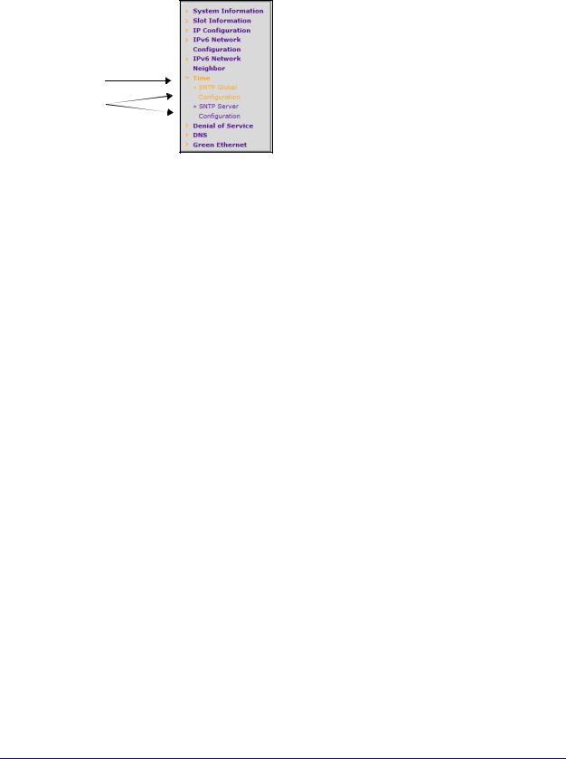
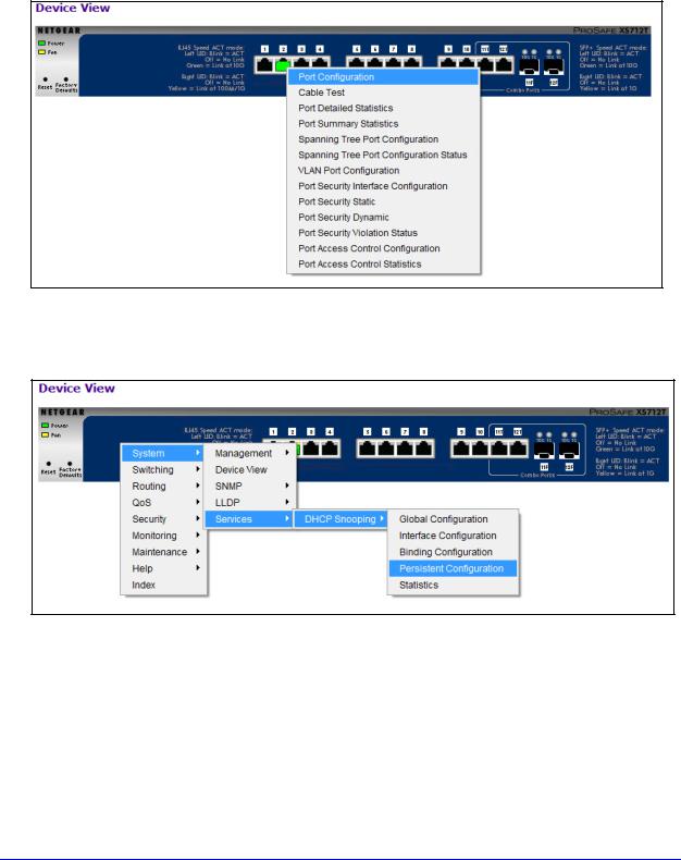
The configuration screens for each feature are available as links in the menu on the left side of the screen. Some items in the menu expand to reveal multiple submenu links, as Figure 2 on page 18 shows. When you click a link that includes multiple submenu links, the item is preceded by a down arrow symbol and expands to display the additional screens.
17
XS712T Smart Switch
Link
Submenu
Links
Figure 2. Menu hierarchy
Configuration and Status Options
The area directly under the configuration menus and to the right of the links displays the configuration information or status for the screen you select. On screens that contain configuration options, you can input information into fields or select options from drop-down lists.
Each screen contains access to the HTML-based help that explains the fields and configuration options for the screen. Each screen also contains command buttons.
The following table shows the command buttons that are used throughout the screens in the web interface:
Table 1. Command buttons
Button |
Function |
|
|
Add |
Places the new item configured in the heading row of a table. |
|
|
Apply |
Sends the updated configuration to the switch. Configuration changes take effect |
|
immediately. |
|
|
Cancel |
Abandons the configuration changes on the screen and resets the data to the previous |
|
values. |
|
|
Delete |
Removes the selected item. |
|
|
Refresh |
Refreshes the screen with the latest information from the device. |
|
|
Logout |
Ends the session. |
|
|
Clear |
Clears all information and returns the switch to its default settings. |
|
|
18
XS712T Smart Switch
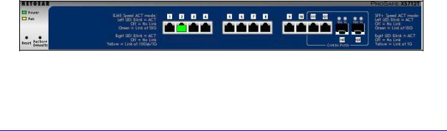
Device View
The Device View is a Java applet that displays the ports on the switch. This graphic provides an alternate way to navigate to configuration and monitoring options. The graphic also provides information about device ports, current configuration and status, table information, and feature components.
The Device View is available by selecting System Device View.
Depending upon the status of the port, the color of a port in the Device View is either red, green, or black. Green indicates that the port is enabled. Red indicates that an error has occurred on the port or that the port is administratively disabled. A port that is black does not have a link.
The port speed LED is either green or yellow.
•Solid green. A valid 10 Gbps link is established
•Blinking green. Packets transmitting/receiving is occurring at 10 Gbps
•Solid yellow. a valid 100/1000 Mbps link is established
•Blinking yellow. packets transmitting/receiving is occurring at 100/1000 Mbps
The System LEDs are located on the left side of the front panel.
Power/Status LED
The Power LED is a bicolor LED that serves as an indicator of power and diagnostic status. The following indications are given by the following LED states:
•A solid green LED indicates that the power is supplied to the switch and operating normally.
•A solid yellow LED indicates that system is in the boot-up stage.
•No lit LED indicates that power is disconnected.
FAN Status LED
FAN status is indicated as follows:
•A solid yellow LED indicates that the fan is faulty.
•No lit LED indicates that the fan is operating normally.
The following image shows the Device View of the XS712T.
Figure 3. Device view
19
XS712T Smart Switch
Click the port you want to view or configure to see a menu that displays statistics and configuration options. Select the menu option to access the screen that contains the configuration or monitoring options.
If you click the graphic, but do not click a specific port, the main menu displays, as the following figure shows. This menu contains the same option as the navigation tabs at the top of the screen.
Help Access
Every screen contains a button to launch online help  , which contains information to assist in configuring and managing the switch. The online help screens are context-sensitive. For example, if the IP Addressing screen is open, the help topic for that screen displays if you click Help.
20
XS712T Smart Switch
User-Defined Fields
User-defined fields can contain 1 to 159 characters, unless otherwise noted in the field label on the configuration screen. All alphanumeric and special characters can be used except for the following (unless specifically noted for that feature):
Table 2. Disallowed characters in user-defined fields
Character |
Definition |
|
|
\ |
Backslash |
|
|
/ |
Forwards slash |
|
|
* |
Asterisk |
|
|
? |
Question mark |
|
|
< |
Less than |
|
|
> |
Greater than |
|
|
| |
Pipe |
|
|
Use SNMPv3
The XS712T Smart Switch software supports the configuration of SNMP groups and users that can manage traps that the SNMP agent generates.
The XS712T Smart Switch use both standard public MIBs for standard functionality and private MIBs that support additional switch functionality. All private MIBs begin with a hyphen (-) prefix. The main object for interface configuration is in -SWITCHING-MIB, which is a private MIB. Some interface configurations also involve objects in the public MIB, IF-MIB.
SNMP is enabled by default. The System Information screen, which is the screen that displays after a successful login, displays the information you need to configure an SNMP manager to access the switch. To configure information for SNMPv1 or SNMPv2, see
SNMPV1/V2 on page 53.
Any user can connect to the switch using the SNMPv3 protocol, but for authentication and encryption, the switch supports only one user which is admin; therefore there is only one profile that can be created or modified.
21
XS712T Smart Switch
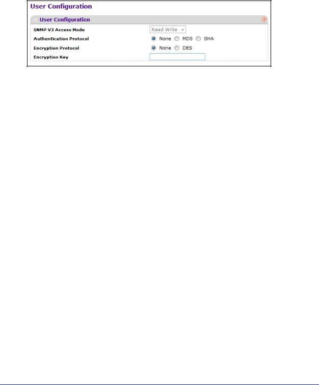
To configure authentication and encryption settings for the SNMPv3 admin profile by using the web interface:
1.Select System SNMP SNMPv3 User Configuration. The User Configuration screen displays.
The SNMPv3 Access Mode is a read-only field that shows the access privileges for the user account. The admin account always has Read/Write access, and all other accounts have Read Only access.
2.To enable authentication, select an Authentication Protocol option.
If the authentication protocol is MD5 or SHA, the user login password will be used as SNMPv3 authentication password. To configure the login password, see Change Password on page 171.
3.To enable encryption:
a.In the Encryption Protocol field, select the DES option to encrypt SNMPv3 packets using the DES encryption protocol.
b.In the Encryption Key field, enter an encryption code of eight or more alphanumeric characters.
4.Click Apply.
22

XS712T Smart Switch
Interface Naming Convention
The switch supports physical and logical interfaces. Interfaces are identified by their type and the interface number. All the physical ports are as follows:
•Ports 1–10. Copper ports that operate at 100MB, 1G, or 10G.
•Ports 11–12. Combo ports that can act as 100M/1G/10G copper ports or 1G/10G SFP+ ports.
The number of the port is identified on the front panel. You can configure the logical interfaces by using the software. The following table describes the naming convention for all interfaces available on the switch.
Table 3. Interface naming conventions
Interface |
Description |
Example |
|
|
|
Physical |
The physical ports include 10 gigabit ports and are |
xg1, xg2, xg3 |
|
numbered sequentially starting from one using the following |
|
|
format: xgX. xg stands for 10G port and X is the port |
|
|
number. |
|
|
|
|
Link aggregation group (LAG) |
LAG interfaces are logical interfaces that are only used for |
l1, l2, l3 |
|
bridging functions. |
|
CPU management interface |
This is the internal switch interface responsible for the |
c1 |
|
switch base MAC address. This interface is not |
|
|
configurable and is always listed in the MAC Address |
|
|
Table. |
|
|
|
|
23
XS712T Smart Switch
Online Help
The Help main navigation tab of the web management interface provides access to the menus that are described in the following sections:
•Support
•User Guide
Support
The Support screen provides access to the NETGEAR support website at support.netgear.com.
To access the support website from the web management interface:
1.Select Help Support..
The Support screen displays.
2.Click Apply to access the NETGEAR support site for the switch.
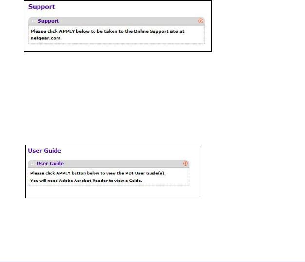
User Guide
The XS712T Smart Switch Software Administration Manual (the guide you are now reading) is available at the NETGEAR download center at downloadcenter.netgear.com.
To access the reference manual online from the web management interface:
1.Select Help User Guide.
2.Click Apply to access the NETGEAR download center.
3.Enter the model number of the switch.
4.Locate the XS712T Smart Switch Software Administration Manual on the product support web screen.
24
XS712T Smart Switch
Registration
To qualify for product updates and product warranty, NETGEAR encourages you to register your product. The first time that you connect to the switch while it is connected to the Internet, you have the option to register your product. At any time, you can register your product from the web management interface, or you can visit the NETGEAR website for registration at https://my.netgear.com/registration/login.aspx.
To register the switch with NETGEAR:
1.Select Help > Register.
The Registration screen displays.
2.Click Register.
A pop-up window opens and displays the NETGEAR product registration web screen.
3.Complete the registration form.
4.Click Submit.
25

2. Configure System Information |
2 |
|
|
||
|
|
|
Use the features you access from the System navigation tab to define the switch’s relationship to its environment. The System navigation tab provides access to the configuration menus described in the following sections:
•Management
•SNMP
•LLDP
•Services—DHCP Snooping
Management
This section describes how to display the switch status and specify some basic switch information, such as the management interface IP address, system clock settings, and DNS information. From the Management configuration menu, you can access the following links:
•System Information
•IP Configuration
•IPv6 Network Configuration
•IPv6 Network Neighbor
•Time
•Denial of Service
•DNS
•Green Ethernet
26
XS712T Smart Switch
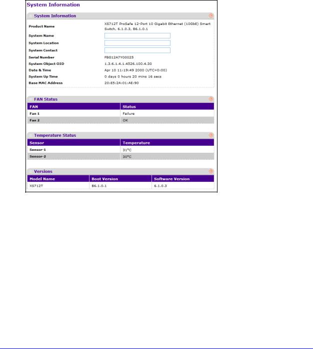
System Information
After a successful login, the System Information screen displays. Use this screen to configure and view general device information.
To define a system name, location, and contact:
1.Select System Management System Information. The System Information screen displays.
2.Define the following fields:
•System Name. Enter the name you want to use to identify this switch. You can use up to 255 alphanumeric characters. The factory default is blank.
•System Location. Enter the location of this switch. You can use up to 255 alphanumeric characters. The factory default is blank.
•System Contact. Enter the contact person for this switch. You can use up to 255 alphanumeric characters. The factory default is blank.
3.Click Apply.
The system parameters are applied, and the device is updated.
27

XS712T Smart Switch
The following table describes the status information the System Information screen displays.
Table 4. System Information screen status fields
Field |
Description |
Product Name |
The product name that describes the switch. |
|
|
Serial Number |
The serial number of the switch. |
|
|
System Object ID |
The base object ID for the switch's enterprise MIB. |
|
|
Date & Time |
The current date and time. |
|
|
System Up Time |
Displays the number of days, hours, and minutes since the last |
|
system restart. |
|
|
Base MAC Address |
The universally assigned network address. |
|
|
Model Name |
The model name of the switch. |
|
|
Temperature Status |
This table shows temperature of different system sensors. The |
|
temperature is instant and can be refreshed when the REFRESH |
|
button is pressed. The maximum temperature of CPU and MACs |
|
depends on the actual hardware. |
|
|
Fan Status |
The screen shows the status of the fans. These fans remove the heat |
|
generated by the power, CPU and other chipsets, make chipsets |
|
work normally. Fan status has three possible values: OK, Failure, Not |
|
Present. |
|
|
Boot Version |
The boot code version of the switch. |
|
|
Software Version |
The software version of the switch. |
|
|
28
XS712T Smart Switch
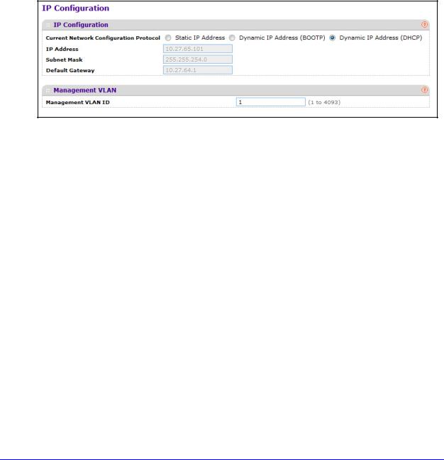
IP Configuration
Use the IP Configuration screen to configure network information for the management interface, which is the logical interface used for in-band connectivity with the switch through any of the switch's front-panel ports. The configuration parameters associated with the switch’s network interface do not affect the configuration of the front panel ports through which traffic is switched or routed.
To configure the network information for the management interface:
1.Select System Management IP Configuration. The IP Configuration screen displays.
2.Select the appropriate radio button to determine how to configure the network information for the switch management interface:
•Dynamic IP Address (DHCP). Specifies that the switch must obtain the IP address through a DHCP server.
•Dynamic IP Address (BOOTP). Specifies that the switch must obtain the IP address through a BootP server.
•Static IP Address. Specifies that the IP address, subnet mask, and default gateway must be manually configured. Enter this information in the fields below this radio button.
3.If you selected the Static IP Address option, configure the following network information:
•IP Address. The IP address of the network interface. The factory default value is 192.168.0.239. Each part of the IP address must start with a number other than zero. For example, IP addresses 001.100.192.6 and 192.001.10.3 are not valid.
•Subnet Mask. The IP subnet mask for the interface. The factory default value is 255.255.255.0.
•Default Gateway. The default gateway for the IP interface. The factory default value is 192.168.0.254.
29

XS712T Smart Switch
4. Specify the VLAN ID for the management VLAN.
Note: Make sure that the VLAN to be configured as the management VLAN exists. And make sure that the PVID of at least one port that is a port of the VLAN is the same as the management VLAN ID. For information about creating VLANs and configuring the PVID for a port, see VLANs on page 84.
The management VLAN is used to establish an IP connection to the switch from a workstation that is connected to a port in the same VLAN. If not specified, the active management VLAN ID is 1 (default), which allows an IP connection to be established through any port.
When the management VLAN is set to a different value, an IP connection can be made only through a port that is part of the management VLAN. It is also mandatory that the port VLAN ID (PVID) of the port to be connected in that management VLAN be the same as the management VLAN ID.
The management VLAN has the following requirements:
•Only one management VLAN can be active at a time.
•When a new management VLAN is configured, connectivity through the existing management VLAN is lost.
•The management station should be reconnected to the port in the new management VLAN.
5.Click Apply.
30
 Loading...