


 Loading...
ProSafe M5300 Switch
Web Management User Guide
350 East Plumeria Drive
San Jose, CA 95134
USA
August 2012 202-10976-01 v1.0

ProSafe M5300 Switch
© NETGEAR, Inc. All rights reserved
No part of this publication may be reproduced, transmitted, transcribed, stored in a retrieval system, or translated into any language in any form or by any means without the written permission of NETGEAR, Inc.
NETGEAR, the NETGEAR logo, and Connect with Innovation are trademarks and/or registered trademarks of NETGEAR, Inc. and/or its subsidiaries in the United States and/or other countries. Information is subject to change without notice. Other brand and product names are registered trademarks or trademarks of their respective holders. © NETGEAR, Inc. All rights reserved.
Technical Support
Thank you for choosing NETGEAR. To register your product, get the latest product updates, get support online, or for more information about the topics covered in this manual, visit the Support website at
http://support.netgear.com
Phone (US & Canada only): 1-888-NETGEAR
Phone (Other Countries): Check the list of phone numbers at http://support.netgear.com/app/answers/detail/a_id/984
Statement of Conditions
To improve internal design, operational function, and/or reliability, NETGEAR reserves the right to make changes to the products described in this document without notice. NETGEAR does not assume any liability that may occur due to the use, or application of, the product(s) or circuit layout(s) described herein.
Revision History
Publication Part Number |
Version |
Publish Date |
Comments |
|
|
|
|
202-10976-01 |
v1.0 |
August 2012 |
First publication |
|
|
|
|
2

Contents
Chapter 1 Getting Started
Switch Management Interface . . . . . . . . . . . . . . . . . . . . . . . . . . . . . . . . . . . 9
Web Access . . . . . . . . . . . . . . . . . . . . . . . . . . . . . . . . . . . . . . . . . . . . . . . . . 9
Understanding the User Interfaces. . . . . . . . . . . . . . . . . . . . . . . . . . . . . . . 10
Using the Web Interface . . . . . . . . . . . . . . . . . . . . . . . . . . . . . . . . . . . . . 10
Interface Naming Convention . . . . . . . . . . . . . . . . . . . . . . . . . . . . . . . . . . . 17
Chapter 2 Configuring System Information
Management. . . . . . . . . . . . . . . . . . . . . . . . . . . . . . . . . . . . . . . . . . . . . . . . 19
System Information. . . . . . . . . . . . . . . . . . . . . . . . . . . . . . . . . . . . . . . . . 20
Switch Statistics . . . . . . . . . . . . . . . . . . . . . . . . . . . . . . . . . . . . . . . . . . . 24
System CPU Status . . . . . . . . . . . . . . . . . . . . . . . . . . . . . . . . . . . . . . . . 26
Slot Information . . . . . . . . . . . . . . . . . . . . . . . . . . . . . . . . . . . . . . . . . . . 27
Loopback Interface . . . . . . . . . . . . . . . . . . . . . . . . . . . . . . . . . . . . . . . . . 29
Network Interface . . . . . . . . . . . . . . . . . . . . . . . . . . . . . . . . . . . . . . . . . . 30
Time . . . . . . . . . . . . . . . . . . . . . . . . . . . . . . . . . . . . . . . . . . . . . . . . . . . . 34
DNS . . . . . . . . . . . . . . . . . . . . . . . . . . . . . . . . . . . . . . . . . . . . . . . . . . . . 40
SDM Template Preference . . . . . . . . . . . . . . . . . . . . . . . . . . . . . . . . . . . 42
License . . . . . . . . . . . . . . . . . . . . . . . . . . . . . . . . . . . . . . . . . . . . . . . . . . . . 43
License Key . . . . . . . . . . . . . . . . . . . . . . . . . . . . . . . . . . . . . . . . . . . . . . 43
License Features . . . . . . . . . . . . . . . . . . . . . . . . . . . . . . . . . . . . . . . . . . 44
Services . . . . . . . . . . . . . . . . . . . . . . . . . . . . . . . . . . . . . . . . . . . . . . . . . . . 45
DHCP Server . . . . . . . . . . . . . . . . . . . . . . . . . . . . . . . . . . . . . . . . . . . . . 45
DHCP Relay . . . . . . . . . . . . . . . . . . . . . . . . . . . . . . . . . . . . . . . . . . . . . . 53
DHCP L2 Relay . . . . . . . . . . . . . . . . . . . . . . . . . . . . . . . . . . . . . . . . . . . 54
UDP Relay . . . . . . . . . . . . . . . . . . . . . . . . . . . . . . . . . . . . . . . . . . . . . . . 57
DHCPv6 Server . . . . . . . . . . . . . . . . . . . . . . . . . . . . . . . . . . . . . . . . . . . 59
DHCPv6 Relay . . . . . . . . . . . . . . . . . . . . . . . . . . . . . . . . . . . . . . . . . . . . 66
Stacking . . . . . . . . . . . . . . . . . . . . . . . . . . . . . . . . . . . . . . . . . . . . . . . . . . . 68
Stack Features . . . . . . . . . . . . . . . . . . . . . . . . . . . . . . . . . . . . . . . . . . . . 68
Firmware Synchronization and Upgrade . . . . . . . . . . . . . . . . . . . . . . . . 69
Configuration Maintenance. . . . . . . . . . . . . . . . . . . . . . . . . . . . . . . . . . . 69
Stack Master Election. . . . . . . . . . . . . . . . . . . . . . . . . . . . . . . . . . . . . . . 70
Factory Defaults Reset Behavior . . . . . . . . . . . . . . . . . . . . . . . . . . . . . . 70
Nonstop Forwarding . . . . . . . . . . . . . . . . . . . . . . . . . . . . . . . . . . . . . . . . 71
Stack Configuration . . . . . . . . . . . . . . . . . . . . . . . . . . . . . . . . . . . . . . . . 72
Stack Port Configuration. . . . . . . . . . . . . . . . . . . . . . . . . . . . . . . . . . . . . 74
Stack Port Diagnostics . . . . . . . . . . . . . . . . . . . . . . . . . . . . . . . . . . . . . . 76
Stack Firmware Synchronization . . . . . . . . . . . . . . . . . . . . . . . . . . . . . . 77
3

ProSafe M5300 Switch
NSF . . . . . . . . . . . . . . . . . . . . . . . . . . . . . . . . . . . . . . . . . . . . . . . . . . . . 78
Checkpoint Statistics . . . . . . . . . . . . . . . . . . . . . . . . . . . . . . . . . . . . . . . 80
Stack Template Summary . . . . . . . . . . . . . . . . . . . . . . . . . . . . . . . . . . . 81
Stack Template Configuration . . . . . . . . . . . . . . . . . . . . . . . . . . . . . . . . 82
PoE (M5300-28G-POE+ and M5300-52G-POE+ Only) . . . . . . . . . . . . . . . 82
Basic PoE Configuration. . . . . . . . . . . . . . . . . . . . . . . . . . . . . . . . . . . . . 83
PoE Port Configuration. . . . . . . . . . . . . . . . . . . . . . . . . . . . . . . . . . . . . . 84
SNMP . . . . . . . . . . . . . . . . . . . . . . . . . . . . . . . . . . . . . . . . . . . . . . . . . . . . . 87
SNMPV1/V2 . . . . . . . . . . . . . . . . . . . . . . . . . . . . . . . . . . . . . . . . . . . . . . 87
SNMP V3 User Configuration. . . . . . . . . . . . . . . . . . . . . . . . . . . . . . . . . 92
LLDP . . . . . . . . . . . . . . . . . . . . . . . . . . . . . . . . . . . . . . . . . . . . . . . . . . . . . 93
LLDP. . . . . . . . . . . . . . . . . . . . . . . . . . . . . . . . . . . . . . . . . . . . . . . . . . . . 93
LLDP-MED . . . . . . . . . . . . . . . . . . . . . . . . . . . . . . . . . . . . . . . . . . . . . . 100
ISDP . . . . . . . . . . . . . . . . . . . . . . . . . . . . . . . . . . . . . . . . . . . . . . . . . . . . . 109
ISDP Global Configuration . . . . . . . . . . . . . . . . . . . . . . . . . . . . . . . . . . 109
Advanced ISDP Configuration . . . . . . . . . . . . . . . . . . . . . . . . . . . . . . . 110
Timer Schedule . . . . . . . . . . . . . . . . . . . . . . . . . . . . . . . . . . . . . . . . . . . . 114
Timer Global Configuration. . . . . . . . . . . . . . . . . . . . . . . . . . . . . . . . . . 114
Timer Schedule Configuration . . . . . . . . . . . . . . . . . . . . . . . . . . . . . . . 115
Chapter 3 Configuring Switching Information
VLANs . . . . . . . . . . . . . . . . . . . . . . . . . . . . . . . . . . . . . . . . . . . . . . . . . . . 119 Basic. . . . . . . . . . . . . . . . . . . . . . . . . . . . . . . . . . . . . . . . . . . . . . . . . . . 120 Advanced . . . . . . . . . . . . . . . . . . . . . . . . . . . . . . . . . . . . . . . . . . . . . . . 122 Auto-VoIP Configuration. . . . . . . . . . . . . . . . . . . . . . . . . . . . . . . . . . . . . . 134 Protocol-Based . . . . . . . . . . . . . . . . . . . . . . . . . . . . . . . . . . . . . . . . . . . 134 OUI-Based . . . . . . . . . . . . . . . . . . . . . . . . . . . . . . . . . . . . . . . . . . . . . . 136 iSCSI . . . . . . . . . . . . . . . . . . . . . . . . . . . . . . . . . . . . . . . . . . . . . . . . . . . . 139 Basic. . . . . . . . . . . . . . . . . . . . . . . . . . . . . . . . . . . . . . . . . . . . . . . . . . . 139 Advanced . . . . . . . . . . . . . . . . . . . . . . . . . . . . . . . . . . . . . . . . . . . . . . . 141 Spanning Tree Protocol . . . . . . . . . . . . . . . . . . . . . . . . . . . . . . . . . . . . . . 143 Basic. . . . . . . . . . . . . . . . . . . . . . . . . . . . . . . . . . . . . . . . . . . . . . . . . . . 143 Advanced . . . . . . . . . . . . . . . . . . . . . . . . . . . . . . . . . . . . . . . . . . . . . . . 145 Multicast . . . . . . . . . . . . . . . . . . . . . . . . . . . . . . . . . . . . . . . . . . . . . . . . . . 156 MFDB . . . . . . . . . . . . . . . . . . . . . . . . . . . . . . . . . . . . . . . . . . . . . . . . . . 156 IGMP Snooping . . . . . . . . . . . . . . . . . . . . . . . . . . . . . . . . . . . . . . . . . . 158 MLD Snooping . . . . . . . . . . . . . . . . . . . . . . . . . . . . . . . . . . . . . . . . . . . 167 MVR Configuration . . . . . . . . . . . . . . . . . . . . . . . . . . . . . . . . . . . . . . . . . . 173 Basic. . . . . . . . . . . . . . . . . . . . . . . . . . . . . . . . . . . . . . . . . . . . . . . . . . . 173 Advanced . . . . . . . . . . . . . . . . . . . . . . . . . . . . . . . . . . . . . . . . . . . . . . . 174 Address Table . . . . . . . . . . . . . . . . . . . . . . . . . . . . . . . . . . . . . . . . . . . . . 177 Basic. . . . . . . . . . . . . . . . . . . . . . . . . . . . . . . . . . . . . . . . . . . . . . . . . . . 177 Advanced . . . . . . . . . . . . . . . . . . . . . . . . . . . . . . . . . . . . . . . . . . . . . . . 179 Ports . . . . . . . . . . . . . . . . . . . . . . . . . . . . . . . . . . . . . . . . . . . . . . . . . . . . . 181 Port Configuration. . . . . . . . . . . . . . . . . . . . . . . . . . . . . . . . . . . . . . . . . 181 Port Description . . . . . . . . . . . . . . . . . . . . . . . . . . . . . . . . . . . . . . . . . . 182 Link Aggregation Groups . . . . . . . . . . . . . . . . . . . . . . . . . . . . . . . . . . . . . 184
4

ProSafe M5300 Switch
LAG Configuration . . . . . . . . . . . . . . . . . . . . . . . . . . . . . . . . . . . . . . . .184
LAG Membership . . . . . . . . . . . . . . . . . . . . . . . . . . . . . . . . . . . . . . . . .186
Chapter 4 Routing
Routing Table . . . . . . . . . . . . . . . . . . . . . . . . . . . . . . . . . . . . . . . . . . . . . .189
Basic . . . . . . . . . . . . . . . . . . . . . . . . . . . . . . . . . . . . . . . . . . . . . . . . . . .190
Advanced . . . . . . . . . . . . . . . . . . . . . . . . . . . . . . . . . . . . . . . . . . . . . . .192
IP . . . . . . . . . . . . . . . . . . . . . . . . . . . . . . . . . . . . . . . . . . . . . . . . . . . . . . .193
Basic . . . . . . . . . . . . . . . . . . . . . . . . . . . . . . . . . . . . . . . . . . . . . . . . . . .193
Advanced . . . . . . . . . . . . . . . . . . . . . . . . . . . . . . . . . . . . . . . . . . . . . . .197
IPv6 . . . . . . . . . . . . . . . . . . . . . . . . . . . . . . . . . . . . . . . . . . . . . . . . . . . . .201
Basic . . . . . . . . . . . . . . . . . . . . . . . . . . . . . . . . . . . . . . . . . . . . . . . . . . .201
Advanced . . . . . . . . . . . . . . . . . . . . . . . . . . . . . . . . . . . . . . . . . . . . . . .204
VLAN . . . . . . . . . . . . . . . . . . . . . . . . . . . . . . . . . . . . . . . . . . . . . . . . . . . .218
VLAN Routing Wizard. . . . . . . . . . . . . . . . . . . . . . . . . . . . . . . . . . . . . .218
VLAN Routing Configuration. . . . . . . . . . . . . . . . . . . . . . . . . . . . . . . . .219
ARP . . . . . . . . . . . . . . . . . . . . . . . . . . . . . . . . . . . . . . . . . . . . . . . . . . . . .220
Basic . . . . . . . . . . . . . . . . . . . . . . . . . . . . . . . . . . . . . . . . . . . . . . . . . . .221
Advanced . . . . . . . . . . . . . . . . . . . . . . . . . . . . . . . . . . . . . . . . . . . . . . .221
RIP . . . . . . . . . . . . . . . . . . . . . . . . . . . . . . . . . . . . . . . . . . . . . . . . . . . . . .225
Basic . . . . . . . . . . . . . . . . . . . . . . . . . . . . . . . . . . . . . . . . . . . . . . . . . . .225
Advanced . . . . . . . . . . . . . . . . . . . . . . . . . . . . . . . . . . . . . . . . . . . . . . .226
OSPF . . . . . . . . . . . . . . . . . . . . . . . . . . . . . . . . . . . . . . . . . . . . . . . . . . . .232
Basic . . . . . . . . . . . . . . . . . . . . . . . . . . . . . . . . . . . . . . . . . . . . . . . . . . .232
Advanced . . . . . . . . . . . . . . . . . . . . . . . . . . . . . . . . . . . . . . . . . . . . . . .233
OSPFv3 . . . . . . . . . . . . . . . . . . . . . . . . . . . . . . . . . . . . . . . . . . . . . . . . . .257
Basic . . . . . . . . . . . . . . . . . . . . . . . . . . . . . . . . . . . . . . . . . . . . . . . . . . .257
Advanced . . . . . . . . . . . . . . . . . . . . . . . . . . . . . . . . . . . . . . . . . . . . . . .258
Router Discovery . . . . . . . . . . . . . . . . . . . . . . . . . . . . . . . . . . . . . . . . . . .279
Router Discovery Configuration . . . . . . . . . . . . . . . . . . . . . . . . . . . . . .279
VRRP . . . . . . . . . . . . . . . . . . . . . . . . . . . . . . . . . . . . . . . . . . . . . . . . . . . .280
Basic . . . . . . . . . . . . . . . . . . . . . . . . . . . . . . . . . . . . . . . . . . . . . . . . . . .280
Advanced . . . . . . . . . . . . . . . . . . . . . . . . . . . . . . . . . . . . . . . . . . . . . . .282
Multicast . . . . . . . . . . . . . . . . . . . . . . . . . . . . . . . . . . . . . . . . . . . . . . . . . .286
Mroute Table. . . . . . . . . . . . . . . . . . . . . . . . . . . . . . . . . . . . . . . . . . . . .287
Multicast Global Configuration . . . . . . . . . . . . . . . . . . . . . . . . . . . . . . .288
Multicast Interface Configuration . . . . . . . . . . . . . . . . . . . . . . . . . . . . .289
DVMRP. . . . . . . . . . . . . . . . . . . . . . . . . . . . . . . . . . . . . . . . . . . . . . . . .290
IGMP. . . . . . . . . . . . . . . . . . . . . . . . . . . . . . . . . . . . . . . . . . . . . . . . . . .296
PIM . . . . . . . . . . . . . . . . . . . . . . . . . . . . . . . . . . . . . . . . . . . . . . . . . . . .304
Static Routes Configuration . . . . . . . . . . . . . . . . . . . . . . . . . . . . . . . . .311
Admin Boundary Configuration. . . . . . . . . . . . . . . . . . . . . . . . . . . . . . .312
IPv6 Multicast . . . . . . . . . . . . . . . . . . . . . . . . . . . . . . . . . . . . . . . . . . . . . .313
Mroute Table. . . . . . . . . . . . . . . . . . . . . . . . . . . . . . . . . . . . . . . . . . . . .313
IPv6 PIM . . . . . . . . . . . . . . . . . . . . . . . . . . . . . . . . . . . . . . . . . . . . . . . .314
MLD . . . . . . . . . . . . . . . . . . . . . . . . . . . . . . . . . . . . . . . . . . . . . . . . . . .321
Static Routes Configuration . . . . . . . . . . . . . . . . . . . . . . . . . . . . . . . . .329
5

ProSafe M5300 Switch
Chapter 5 Configuring Quality of Service
Class of Service . . . . . . . . . . . . . . . . . . . . . . . . . . . . . . . . . . . . . . . . . . . . 331
Basic. . . . . . . . . . . . . . . . . . . . . . . . . . . . . . . . . . . . . . . . . . . . . . . . . . . 332
Advanced . . . . . . . . . . . . . . . . . . . . . . . . . . . . . . . . . . . . . . . . . . . . . . . 333
Differentiated Services . . . . . . . . . . . . . . . . . . . . . . . . . . . . . . . . . . . . . . . 339
DiffServ Wizard. . . . . . . . . . . . . . . . . . . . . . . . . . . . . . . . . . . . . . . . . . . 340
Basic. . . . . . . . . . . . . . . . . . . . . . . . . . . . . . . . . . . . . . . . . . . . . . . . . . . 341
Advanced . . . . . . . . . . . . . . . . . . . . . . . . . . . . . . . . . . . . . . . . . . . . . . . 343
Chapter 6 Managing Device Security
Management Security Settings . . . . . . . . . . . . . . . . . . . . . . . . . . . . . . . . 355
Local User . . . . . . . . . . . . . . . . . . . . . . . . . . . . . . . . . . . . . . . . . . . . . . 356
Enable Password Configuration . . . . . . . . . . . . . . . . . . . . . . . . . . . . . . 358
Line Password Configuration . . . . . . . . . . . . . . . . . . . . . . . . . . . . . . . . 358
RADIUS . . . . . . . . . . . . . . . . . . . . . . . . . . . . . . . . . . . . . . . . . . . . . . . . 359
Configuring TACACS+ . . . . . . . . . . . . . . . . . . . . . . . . . . . . . . . . . . . . . 364
Authentication List Configuration . . . . . . . . . . . . . . . . . . . . . . . . . . . . . 366
Login Sessions . . . . . . . . . . . . . . . . . . . . . . . . . . . . . . . . . . . . . . . . . . . 371
Configuring Management Access . . . . . . . . . . . . . . . . . . . . . . . . . . . . . . 372
HTTP . . . . . . . . . . . . . . . . . . . . . . . . . . . . . . . . . . . . . . . . . . . . . . . . . . 372
HTTPS . . . . . . . . . . . . . . . . . . . . . . . . . . . . . . . . . . . . . . . . . . . . . . . . . 373
SSH . . . . . . . . . . . . . . . . . . . . . . . . . . . . . . . . . . . . . . . . . . . . . . . . . . . 377
Telnet . . . . . . . . . . . . . . . . . . . . . . . . . . . . . . . . . . . . . . . . . . . . . . . . . . 380
Console Port. . . . . . . . . . . . . . . . . . . . . . . . . . . . . . . . . . . . . . . . . . . . . 381
Denial of Service . . . . . . . . . . . . . . . . . . . . . . . . . . . . . . . . . . . . . . . . . 382
Access Control . . . . . . . . . . . . . . . . . . . . . . . . . . . . . . . . . . . . . . . . . . . 384
Port Authentication . . . . . . . . . . . . . . . . . . . . . . . . . . . . . . . . . . . . . . . . . . 386
Basic. . . . . . . . . . . . . . . . . . . . . . . . . . . . . . . . . . . . . . . . . . . . . . . . . . . 387
Advanced . . . . . . . . . . . . . . . . . . . . . . . . . . . . . . . . . . . . . . . . . . . . . . . 389
Traffic Control. . . . . . . . . . . . . . . . . . . . . . . . . . . . . . . . . . . . . . . . . . . . . . 397
MAC Filter. . . . . . . . . . . . . . . . . . . . . . . . . . . . . . . . . . . . . . . . . . . . . . . 397
Port Security . . . . . . . . . . . . . . . . . . . . . . . . . . . . . . . . . . . . . . . . . . . . . 399
Private Group . . . . . . . . . . . . . . . . . . . . . . . . . . . . . . . . . . . . . . . . . . . . 404
Protected Ports Configuration . . . . . . . . . . . . . . . . . . . . . . . . . . . . . . . 406
Private VLAN . . . . . . . . . . . . . . . . . . . . . . . . . . . . . . . . . . . . . . . . . . . . 407
Storm Control . . . . . . . . . . . . . . . . . . . . . . . . . . . . . . . . . . . . . . . . . . . . 412
Control . . . . . . . . . . . . . . . . . . . . . . . . . . . . . . . . . . . . . . . . . . . . . . . . . . . 414
DHCP Snooping . . . . . . . . . . . . . . . . . . . . . . . . . . . . . . . . . . . . . . . . . . 414
IP Source Guard. . . . . . . . . . . . . . . . . . . . . . . . . . . . . . . . . . . . . . . . . . 419
Dynamic ARP Inspection . . . . . . . . . . . . . . . . . . . . . . . . . . . . . . . . . . . 421
Captive Portal. . . . . . . . . . . . . . . . . . . . . . . . . . . . . . . . . . . . . . . . . . . . . . 426
Configuring Access Control Lists . . . . . . . . . . . . . . . . . . . . . . . . . . . . . . . 435
ACL Wizard . . . . . . . . . . . . . . . . . . . . . . . . . . . . . . . . . . . . . . . . . . . . . 435
Basic. . . . . . . . . . . . . . . . . . . . . . . . . . . . . . . . . . . . . . . . . . . . . . . . . . . 437
Advanced . . . . . . . . . . . . . . . . . . . . . . . . . . . . . . . . . . . . . . . . . . . . . . . 441
6

ProSafe M5300 Switch
Chapter 7 Monitoring the System
Ports . . . . . . . . . . . . . . . . . . . . . . . . . . . . . . . . . . . . . . . . . . . . . . . . . . . . .457 Port Statistics . . . . . . . . . . . . . . . . . . . . . . . . . . . . . . . . . . . . . . . . . . . .458 Port Detailed Statistics . . . . . . . . . . . . . . . . . . . . . . . . . . . . . . . . . . . . .459 EAP Statistics . . . . . . . . . . . . . . . . . . . . . . . . . . . . . . . . . . . . . . . . . . . .466 Cable Test . . . . . . . . . . . . . . . . . . . . . . . . . . . . . . . . . . . . . . . . . . . . . .467
Logs . . . . . . . . . . . . . . . . . . . . . . . . . . . . . . . . . . . . . . . . . . . . . . . . . . . . .468 Buffered Logs . . . . . . . . . . . . . . . . . . . . . . . . . . . . . . . . . . . . . . . . . . . .469 Command Log Configuration . . . . . . . . . . . . . . . . . . . . . . . . . . . . . . . .470 Console Log Configuration . . . . . . . . . . . . . . . . . . . . . . . . . . . . . . . . . .471 SysLog Configuration . . . . . . . . . . . . . . . . . . . . . . . . . . . . . . . . . . . . . .471 Trap Logs . . . . . . . . . . . . . . . . . . . . . . . . . . . . . . . . . . . . . . . . . . . . . . .472 Event Logs . . . . . . . . . . . . . . . . . . . . . . . . . . . . . . . . . . . . . . . . . . . . . .474 Persistent Logs . . . . . . . . . . . . . . . . . . . . . . . . . . . . . . . . . . . . . . . . . . .476
Port Mirroring . . . . . . . . . . . . . . . . . . . . . . . . . . . . . . . . . . . . . . . . . . . . . .477 Multiple Port Mirroring. . . . . . . . . . . . . . . . . . . . . . . . . . . . . . . . . . . . . .477 sFlow . . . . . . . . . . . . . . . . . . . . . . . . . . . . . . . . . . . . . . . . . . . . . . . . . . . .479 Basic . . . . . . . . . . . . . . . . . . . . . . . . . . . . . . . . . . . . . . . . . . . . . . . . . . .479 Advanced . . . . . . . . . . . . . . . . . . . . . . . . . . . . . . . . . . . . . . . . . . . . . . .480
Chapter 8 Maintenance
Save Configuration . . . . . . . . . . . . . . . . . . . . . . . . . . . . . . . . . . . . . . . . . .483
Save Configuration . . . . . . . . . . . . . . . . . . . . . . . . . . . . . . . . . . . . . . . .483
Auto Install Configuration . . . . . . . . . . . . . . . . . . . . . . . . . . . . . . . . . . .484
Reset . . . . . . . . . . . . . . . . . . . . . . . . . . . . . . . . . . . . . . . . . . . . . . . . . . . .485
Device Reboot . . . . . . . . . . . . . . . . . . . . . . . . . . . . . . . . . . . . . . . . . . .485
Factory Default . . . . . . . . . . . . . . . . . . . . . . . . . . . . . . . . . . . . . . . . . . .486
Password Reset . . . . . . . . . . . . . . . . . . . . . . . . . . . . . . . . . . . . . . . . . .486
Upload File From Switch . . . . . . . . . . . . . . . . . . . . . . . . . . . . . . . . . . . . .487
File Upload . . . . . . . . . . . . . . . . . . . . . . . . . . . . . . . . . . . . . . . . . . . . . .487
HTTP File Upload . . . . . . . . . . . . . . . . . . . . . . . . . . . . . . . . . . . . . . . . .488
USB File Upload . . . . . . . . . . . . . . . . . . . . . . . . . . . . . . . . . . . . . . . . . .489
Download File To Switch . . . . . . . . . . . . . . . . . . . . . . . . . . . . . . . . . . . . .490
File Download . . . . . . . . . . . . . . . . . . . . . . . . . . . . . . . . . . . . . . . . . . . .490
HTTP File Download. . . . . . . . . . . . . . . . . . . . . . . . . . . . . . . . . . . . . . .492
USB File Download. . . . . . . . . . . . . . . . . . . . . . . . . . . . . . . . . . . . . . . .494
File Management . . . . . . . . . . . . . . . . . . . . . . . . . . . . . . . . . . . . . . . . . . .495
Copy . . . . . . . . . . . . . . . . . . . . . . . . . . . . . . . . . . . . . . . . . . . . . . . . . . .495
Dual Image Configuration . . . . . . . . . . . . . . . . . . . . . . . . . . . . . . . . . . .496
Troubleshooting . . . . . . . . . . . . . . . . . . . . . . . . . . . . . . . . . . . . . . . . . . . .497
Ping IPv4 . . . . . . . . . . . . . . . . . . . . . . . . . . . . . . . . . . . . . . . . . . . . . . .497
Ping IPv6 . . . . . . . . . . . . . . . . . . . . . . . . . . . . . . . . . . . . . . . . . . . . . . .498
Traceroute IPv4 . . . . . . . . . . . . . . . . . . . . . . . . . . . . . . . . . . . . . . . . . .499
Traceroute IPv6 . . . . . . . . . . . . . . . . . . . . . . . . . . . . . . . . . . . . . . . . . .500
7

ProSafe M5300 Switch
Chapter 9 Help
Online Help. . . . . . . . . . . . . . . . . . . . . . . . . . . . . . . . . . . . . . . . . . . . . . . . 501
Support . . . . . . . . . . . . . . . . . . . . . . . . . . . . . . . . . . . . . . . . . . . . . . . . . 501
User Guide . . . . . . . . . . . . . . . . . . . . . . . . . . . . . . . . . . . . . . . . . . . . . . 502
Registration . . . . . . . . . . . . . . . . . . . . . . . . . . . . . . . . . . . . . . . . . . . . . . . 503
Appendix A Default Settings
Appendix B Configuration Examples
Virtual Local Area Networks (VLANs) . . . . . . . . . . . . . . . . . . . . . . . . . . . 509 VLAN Example Configuration. . . . . . . . . . . . . . . . . . . . . . . . . . . . . . . . 510 Access Control Lists (ACLs). . . . . . . . . . . . . . . . . . . . . . . . . . . . . . . . . . . 511 MAC ACL Example Configuration . . . . . . . . . . . . . . . . . . . . . . . . . . . . 512 Standard IP ACL Example Configuration . . . . . . . . . . . . . . . . . . . . . . . 513 Differentiated Services (DiffServ) . . . . . . . . . . . . . . . . . . . . . . . . . . . . . . . 514 Class. . . . . . . . . . . . . . . . . . . . . . . . . . . . . . . . . . . . . . . . . . . . . . . . . . . 514 DiffServ Traffic Classes . . . . . . . . . . . . . . . . . . . . . . . . . . . . . . . . . . . . 515 Creating Policies. . . . . . . . . . . . . . . . . . . . . . . . . . . . . . . . . . . . . . . . . . 515 DiffServ Example Configuration . . . . . . . . . . . . . . . . . . . . . . . . . . . . . . 517 802.1X . . . . . . . . . . . . . . . . . . . . . . . . . . . . . . . . . . . . . . . . . . . . . . . . . . . 518 802.1X Example Configuration. . . . . . . . . . . . . . . . . . . . . . . . . . . . . . . 520 MSTP . . . . . . . . . . . . . . . . . . . . . . . . . . . . . . . . . . . . . . . . . . . . . . . . . . . . 521 MSTP Example Configuration . . . . . . . . . . . . . . . . . . . . . . . . . . . . . . . 523
Appendix C Notification of Compliance
Index
8

1. Getting Started |
1 |
|
|
||
|
|
|
This chapter provides an overview of starting your NETGEAR ProSafe M5300 Switch and accessing the user interface. This chapter contains the following sections:
•Switch Management Interface on page 9
•Web Access on page 9
•Understanding the User Interfaces on page 10
•Interface Naming Convention on page 17
Switch Management Interface
The switches in the NETGEAR ProSafe M5300 family contain an embedded Web server and management software for managing and monitoring switch functions. M5300 Series devices function as simple switches without the management software. However, you can use the management software to configure more advanced features that can improve switch efficiency and overall network performance.
Web-based management lets you monitor, configure, and control your switch remotely using a standard Web browser instead of using expensive and complicated SNMP software products. From your Web browser, you can monitor the performance of your switch and optimize its configuration for your network. You can configure all switch features, such as VLANs, QoS, and ACLs by using the Web-based management interface.
Web Access
To access the M5300 Series management interface, open a Web browser and enter the IP address of the switch in the address field.
You must be able to ping the IP address of the M5300 Series management interface from your administrative system for Web access to be available. If you did not change the IP address of the switch from the default value, enter 192.168.1.1 into the address field.
9
ProSafe M5300 Switch
Accessing the switch directly from your Web browser displays the login screen shown below.
Understanding the User Interfaces
ProSafe M5300 software includes a set of comprehensive management functions for configuring and monitoring the system by using one of the following methods:
•Web user interface
•Simple Network Management Protocol (SNMP)
•Command Line Interface (CLI)
Each of the standards-based management methods allows you to configure and monitor the components of the ProSafe M5300 software. The method you use to manage the system depends on your network size and requirements, and on your preference.
The Web Management User Guide Web Management User Guide describes how to use the Web-based interface to manage and monitor the system.
Using the Web Interface
To access the switch by using a Web browser, the browser must meet the following software requirements:
•HTML version 4.0, or later
•HTTP version 1.1, or later
•Java Runtime Environment 1.6 or later
Getting Started
10
ProSafe M5300 Switch
Use the following procedures to log on to the Web interface:
1.Open a Web browser and enter the IP address of the switch in the Web browser address field.
2.The default user name is admin, default password is none (no password). Type the user name into the field on the login screen and then click Login. User names and passwords are case sensitive.
3.After the system authenticates you, the System Information page displays.
The figure below shows the layout of the Managed Switch Web interface.
Navigation Tab |
Feature Link |
|
Help Link |
LOGOUT
Button
Help Page
Page Menu |
Configuration Status and Options |
|
Navigation Tabs, Feature Links, and Page Menu
The navigation tabs along the top of the Web interface give you quick access to the various switch functions. The tabs are always available and remain constant, regardless of which feature you configure.
When you select a tab, the features for that tab appear as links directly under the tabs. The feature links in the blue bar change according to the navigation tab that is selected.
The configuration pages for each feature are available as links in the page menu on the left side of the page. Some items in the menu expand to reveal multiple configuration pages, as the following figure shows. When you click a menu item that includes multiple configuration pages, the item becomes preceded by a down arrow symbol and expands to display the additional pages.
Getting Started
11

ProSafe M5300 Switch
Page Link
Configuration 
Pages 
Configuration and Monitoring Options
The area directly under the feature links and to the right of the page menu displays the configuration information or status for the page you select. On pages that contain configuration options, you can input information into fields or select options from drop-down menus.
Each page contains access to the HTML-based help that explains the fields and configuration options for the page. Each page also contains command buttons.
Table 1 shows the command buttons that are used throughout the pages in the Web interface:
Table 1. Command Buttons
Button |
Function |
|
|
ADD |
Clicking ADD adds the new item configured in the heading row of a table. |
|
|
APPLY |
Clicking APPLY sends the updated configuration to the switch. Configuration changes take |
|
effect immediately. |
CANCEL |
Clicking CANCEL cancels the configuration on the screen and resets the data on the |
|
screen to the latest value of the switch. |
DELETE |
Clicking DELETE removes the selected item. |
|
|
REFRESH |
Clicking REFRESH updates the page with the latest information from the device. |
|
|
LOGOUT |
Clicking the LOGOUT button ends the session. |
|
|
Getting Started
12

ProSafe M5300 Switch
Device View
The Device View is a Java® applet that displays the ports on the switch. This graphic provides an alternate way to navigate to configuration and monitoring options. The graphic also provides information about device ports, current configuration and status, table information, and feature components.
The Device View is available from the System Device View page.
The port coloring indicates whether a port is currently active. Green indicates that the port is enabled, red indicates that an error has occurred on the port or that the link is disabled, and black indicates that the port is not active.
The following figure shows the front-panel Device View of the M5300-52G-POE+ switch.
Stack Unit ID |
Open Full Stack View |
|||
|
Stack Navigation |
|
|
|
|
|
|
||
|
|
|
|
|
|
|
|
|
|
|
|
|
|
|
Front/Back View Toggle
Use the stack navigation buttons to view the stack master or the next/previous members in the stack. Click Full Stack View to see the device view for each stack member on a single page. The following figure shows the full stack view for a stack with two members.
To view the back panel of the switch, click the front/back toggle button (B or F, depending on the current view). The following figure shows the back-panel Device View of the M5300-52G-POE+ switch.
Getting Started
13

ProSafe M5300 Switch
Device View System LEDs
In addition to the port LEDs, the device view provides a representation of the system LEDs on the left side of the front switch panel.
Power/Status LED
The power LED is a bicolor LED that serves as an indicator of power and diagnostic status. The following indications are given by the following LED states:
•A solid green LED indicates that the power is supplied to the switch and operating normally.
•A solid yellow LED indicates that system is in the boot-up stage.
•No lit LED indicates that power is disconnected.
FAN Status LED
FAN status is indicated as follows:
•A solid yellow LED indicates that the fan is faulty.
•No lit LED indicates that the fan is operating normally.
Stack Master LED
The Stack Master LED is lit if there is an active stack link and the unit is in stack mode.
•A solid green LED indicates that the switch acts as a master unit in a stack of switches.
•No lit LED indicates that the switch acts as a slave member in a stack of switches.
Module LEDs
Each switch includes two back-panel XAUI ports that support stacking or Ethernet modules. For the M5300 Series-28G switches, the port numbers are 27 and 28. For M5300 Series-52G switches, the port numbers are 51 and 52. If a back-panel module is present and active, the LED is solid green.
Seven-Segment LED for the Stacking ID
A solid green LED displays the stack ID (1–6).
Getting Started
14

ProSafe M5300 Switch
Device View Navigation
Click the port you want to view or configure to see a menu that displays statistics and configuration options. Click the menu option to access the page that contains the configuration or monitoring options.
If you click the graphic, but do not click a specific port, the main menu appears. This menu contains the same option as the navigation tabs at the top of the page.
Getting Started
15

ProSafe M5300 Switch
Help Page Access
Every page contains a link to the online help  , which contains information to assist in configuring and managing the switch. The online help pages are context sensitive. For example, if the IP Addressing page is open, the help topic for that page displays if you click Help.
User-Defined Fields
User-defined fields can contain 1 to 159 characters, unless otherwise noted on the configuration Web page. All characters may be used except for the following (unless specifically noted in for that feature):
\ |
< |
/ |
>| |
* |
| |
? |
|
Using SNMP
The ProSafe software supports the configuration of SNMP groups and users that can manage traps that the SNMP agent generates.
ProSafe use both standard public MIBs for standard functionality and private MIBs that support additional switch functionality. All private MIBs begin with a “-” prefix. The main object for interface configuration is in -SWITCHING-MIB, which is a private MIB. Some interface configurations also involve objects in the public MIB, IF-MIB.
SNMP is enabled by default. The System Management System Information Web page, which is the page that displays after a successful login, displays the information you need to configure an SNMP manager to access the switch.
Any user can connect to the switch using the SNMPv3 protocol, but for authentication and encryption, the switch supports only one user which is admin; therefore there is only one profile that can be created or modified.
To configure authentication and encryption settings for the SNMPv3 admin profile by using the Web interface:
1.Navigate to the System SNMP SNMPv3 User Configuration page.
2.To enable authentication, select an Authentication Protocol option, which is either MD5 or
SHA.
3.To enable encryption, select the DES option in the Encryption Protocol field. Then, enter an encryption code of eight or more alphanumeric characters in the Encryption Key field.
4.Click APPLY.
To access configuration information for SNMPv1 or SNMPv2, click System SNMP SNMPv1/v2 and click the page that contains the information to configure.
Getting Started
16

ProSafe M5300 Switch
Interface Naming Convention
The ProSafe support physical and logical interfaces. Interfaces are identified by their type and the interface number. The physical ports are gigabit interfaces and are numbered on the front panel. You configure the logical interfaces by using the software. Table 2 describes the naming convention for all interfaces available on the switch.
Table 2. Naming Conventions for Interfaces
Interface |
Description |
Example |
|
|
|
Physical |
The physical ports are in |
1/0/1: Port 1 on stack member 1 |
|
unit/slot/port format, where unit is |
2/0/23: Port 23 on stack member 2 |
|
the stack ID of the switch, slot is the |
|
|
slot ID (always 0 for physical ports), |
|
|
and port is the port ID, which starts |
|
|
at 1 and is identified on the front |
|
|
panel of the switch. |
|
|
|
|
Link Aggregation Group (LAG) |
LAG interfaces are logical |
ch1, ch2, ch3, and so on |
|
interfaces that are only used for |
|
|
bridging functions. |
|
|
|
|
CPU Management Interface |
This is the internal switch interface |
5/1 |
|
responsible for the switch base |
|
|
MAC address. This interface is not |
|
|
configurable and is always listed in |
|
|
the MAC Address Table. |
|
Routing VLAN Interfaces |
This is an interface used for routing |
0/4/1, 0/4/2, 0/4/3, and so on |
|
functionality. The format can be |
or |
|
expressed in vlan id format or |
vlan 1, vlan 2, vlan 3, and so on |
|
unit/slot/interface format, where unit |
|
|
is 0, slot is 4, and interface is the |
|
|
logical VLAN interface ID. |
|
Getting Started
17

ProSafe M5300 Switch
Getting Started
18

2. Configuring System Information |
2 |
|
|
||
|
|
|
Use the features in the System tab to define the switch’s relationship to its environment. The System tab contains links to the following features:
•Management on page 19
•Device View (See Device View on page 12)
•License on page 43
•Services on page 45
•Stacking on page 68
•PoE (M5300-28G-POE+ and M5300-52G-POE+ Only) on page 82
•SNMP on page 87
•LLDP on page 93
•ISDP on page 109
•Timer Schedule on page 114
Management
This section describes how to display the switch status and specify some basic switch information, such as the management interface IP address, system clock settings, and DNS information. From the Management link, you can access the following pages:
•System Information on page 20
•Switch Statistics on page 24
•System CPU Status on page 26
•Loopback Interface on page 29
•Network Interface on page 30
•Time on page 34
•DNS on page 40
•SDM Template Preference on page 42
19

ProSafe M5300 Switch
System Information
After a successful login, the System Information page displays. Use this page to configure and view general device information.
To display the System Information page, click System Management System Information. A screen similar to the following displays.
Configuring System Information
20
ProSafe M5300 Switch
The System Information provides various statuses:
Switch Status
To define system information:
1.In the System Name field, enter the name you want to use to identify this switch. You may use up to 255 alphanumeric characters. The factory default is blank.
2.In the System Location field, enter the location of this switch. You may use up to 255 alphanumeric characters. The factory default is blank.
3.In the System Contact field, enter the contact person for this switch. You may use up to 25 alphanumeric characters. The factory default is blank.
4.In the Login Timeout field, specify how many minutes of inactivity should occur on a serial port connection before the switch closes the connection. Enter a number between 0 and 160: the factory default is 5. Entering 0 disables the timeout.
5.Click APPLY to send the updated screen to the switch and cause the changes to take effect on the switch. These changes will not be retained across a power cycle unless a save is performed.
The following table describes the status information the System Page displays.
Field |
Description |
|
|
Product Name |
The product name of this switch. |
|
|
IPv4 Network Interface |
The IPv4 address and mask assigned to the network interface. |
|
|
IPv6 Network Interface |
The IPv6 prefix and prefix length assigned to the network interface. |
|
|
IPv4 Loopback Interface |
The IPv4 address and mask assigned to the loopback interface. |
|
|
IPv6 Loopback Interface |
The IPv6 prefix and prefix length assigned to the loopback interface. |
|
|
System Date |
The current date and time. If the system has not synchronized with |
|
an SNTP server, the system time and date is probably incorrect by |
|
many years. |
|
|
System Up Time |
The time in days, hours and minutes since the last switch reboot. |
|
|
Current SNTP Sync Status |
Indicates whether the system time has synchronized with an SNTP |
|
server (Success), or has not attempted or failed to synchronize with |
|
an SNTP server (Other). |
|
|
System SNMP OID |
The base object ID for the switch's enterprise MIB. |
|
|
System Mac Address |
Universally assigned network address. |
|
|
Supported Java Plugin Version |
The supported version of Java plugin. |
|
|
Current SNTP Synchronized Time |
The current date and time, if the system time has been synchronized |
|
with an SNTP server; otherwise, this field is Not Synchronized. |
|
|
Configuring System Information
21

ProSafe M5300 Switch
FAN Status
The screen shows the status of the fans in all units. These fans remove the heat generated by the power, CPU, and other chipsets, allowing the chipsets to work normally. Fan status has three possible values: OK, Failure, Not Applicable (NA).
The following table describes the Fan Status information.
Field |
Description |
|
|
Unit ID |
The stack member unit identifier assigned to the |
|
switch which the fan belongs to. |
|
|
CPU 1/CPU2 |
The working status of each CPU fan. |
|
|
Power 1/Power 2 |
The working status of the power supply fan(s). If the |
|
status is N/A, the power supply might not be installed |
|
or active, or the switch model might support a single |
|
power supply. |
|
|
Click REFRESH to refresh the system information of the switch.
Temperature Status
The screen shows the current operating temperature of the switch. The temperature is instant and can be refreshed when the REFRESH button is pressed. The maximum temperature of the switch depends on the actual hardware.
The following table describes the Temperature Status information.
Field |
Description |
|
|
Unit ID |
The stack member unit identifier assigned to the |
|
switch which the fan belongs to. |
|
|
System |
The current temperature of the switch. |
|
|
Click REFRESH to refresh the system information of the switch.
Configuring System Information
22

ProSafe M5300 Switch
Device Status
The screen shows the various inventory information for each device.
The following table describes the Device Status information.
Field |
Description |
|
|
Firmware Version |
The release.version.maintenance.build number of the code currently running |
|
on the switch. For example, if the release was 8, the version was 0, the |
|
maintenance number was 3, and the build number was 11, the format would |
|
be 8.0.3.11. |
|
|
Boot Version |
The version of the boot code which is in the flash memory to load the |
|
firmware into the memory. |
|
|
CPLD Version |
The version of the software for the Complex Programmable Logic Device |
|
(CPLD). |
Serial Number |
The serial number of this switch. |
|
|
AC |
The status of the internal AC power module. |
|
|
Remote |
Indicates the status of the Remote Power Supply (RPS). The status has three |
|
possible values: |
|
• Not Present: RPS bank not connected |
|
• OK: RPS bank connected. |
|
• FAIL: RPS is present, but power is failed. |
|
|
PoE Version |
Version of the PoE controller firmware image. |
|
|
MAX PoE |
Indicates the status of maximum PoE power available on the switch as |
|
follows: |
|
• ON: Indicates less than 7W of PoE power available for another device. |
|
• OFF: Indicates at least 7W of PoE power available for another device. |
|
• N/A: Indicates that PoE is not supported by the unit. |
|
|
Click REFRESH to refresh the system information of the switch.
Configuring System Information
23

ProSafe M5300 Switch
Switch Statistics
Use this page to display the switch statistics.
To display the Switch Statistics page, click System > Management > Switch Statistics. A screen similar to the following displays.
The following table describes Switch Statistics information.
Field |
Description |
|
|
ifIndex |
This object indicates the ifIndex of the interface table entry |
|
associated with the Processor of this switch. |
|
|
Octets Received |
The total number of octets of data received by the processor |
|
(excluding framing bits but including FCS octets). |
|
|
Packets Received Without Errors |
The total number of packets (including broadcast packets and |
|
multicast packets) received by the processor. |
|
|
Unicast Packets Received |
The number of subnetwork-unicast packets delivered to a |
|
higher-layer protocol. |
|
|
Multicast Packets Received |
The total number of packets received that were directed to a |
|
multicast address. Note that this number does not include packets |
|
directed to the broadcast address. |
|
|
Configuring System Information
24

ProSafe M5300 Switch
Field |
Description |
|
|
Broadcast Packets Received |
The total number of packets received that were directed to the |
|
broadcast address. Note that this does not include multicast |
|
packets. |
|
|
Receive Packets Discarded |
The number of inbound packets which were chosen to be discarded |
|
even though no errors had been detected to prevent their being |
|
deliverable to a higher-layer protocol. A possible reason for |
|
discarding a packet could be to free up buffer space. |
Octets Transmitted |
The total number of octets transmitted out of the interface, including |
|
framing characters. |
|
|
Packets Transmitted Without Errors |
The total number of packets transmitted out of the interface. |
|
|
Unicast Packets Transmitted |
The total number of packets that higher-level protocols requested |
|
be transmitted to a subnetwork-unicast address, including those |
|
that were discarded or not sent. |
Multicast Packets Transmitted |
The total number of packets that higher-level protocols requested |
|
be transmitted to a Multicast address, including those that were |
|
discarded or not sent. |
Broadcast Packets Transmitted |
The total number of packets that higher-level protocols requested |
|
be transmitted to the Broadcast address, including those that were |
|
discarded or not sent. |
Transmit Packets Discarded |
The number of outbound packets which were chosen to be |
|
discarded even though no errors had been detected to prevent their |
|
being deliverable to a higher-layer protocol. A possible reason for |
|
discarding a packet could be to free up buffer space. |
|
|
Most Address Entries Ever Used |
The highest number of Forwarding Database Address Table entries |
|
that have been learned by this switch since the most recent reboot. |
Address Entries in Use |
The number of Learned and static entries in the Forwarding |
|
Database Address Table for this switch. |
|
|
Maximum VLAN Entries |
The maximum number of Virtual LANs (VLANs) allowed on this |
|
switch. |
|
|
Most VLAN Entries Ever Used |
The largest number of VLANs that have been active on this switch |
|
since the last reboot. |
Static VLAN Entries |
The number of presently active VLAN entries on this switch that |
|
have been created statically. |
|
|
Dynamic VLAN Entries |
The number of presently active VLAN entries on this switch that |
|
have been created by GVRP registration. |
|
|
VLAN Deletes |
The number of VLANs on this switch that have been created and |
|
then deleted since the last reboot. |
Time Since Counters Last Cleared |
The elapsed time, in days, hours, minutes, and seconds, since the |
|
statistics for this switch were last cleared. |
|
|
Click CLEAR to clear all the counters, resetting all switch summary and detailed statistics to default values. The discarded packets count cannot be cleared.
Configuring System Information
25
ProSafe M5300 Switch
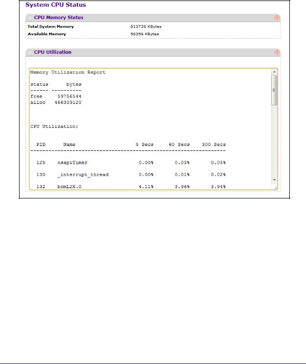
System CPU Status
Use this page to display system CPU status and utilization information.
To display the System Resource page, click System > Management > System CPU Status. A screen similar to the following displays.
System CPU Status
The following table describes CPU Memory Status information.
Field |
Description |
|
|
Total System Memory |
The total memory of the switch in KBytes. |
|
|
Available Memory |
The available memory space for the switch in |
|
KBytes. |
|
|
CPU Utilization Information
This area displays the CPU Utilization information. It displays the amount of available and allocated memory and lists each system process (task) that is running, along with its CPU utilization over the last 5, 60, and 300 seconds.
Configuring System Information
26
ProSafe M5300 Switch
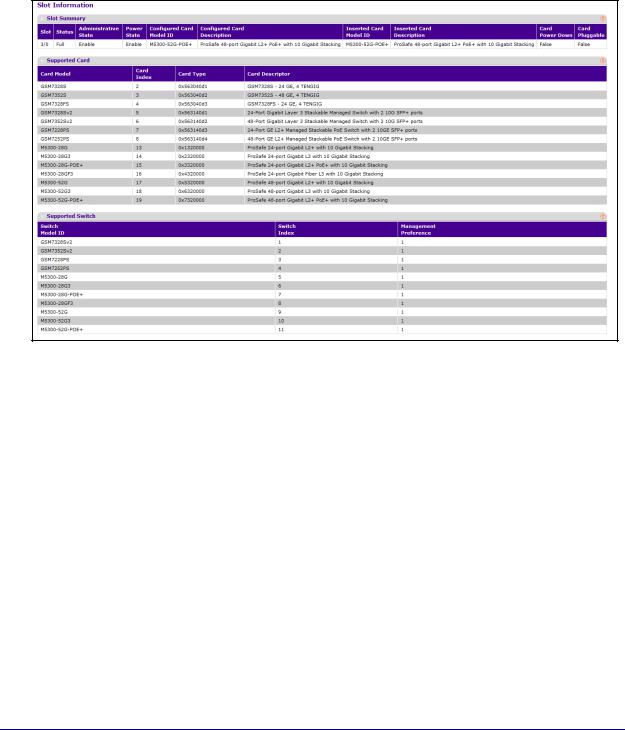
Slot Information
Use this page to view information about the cards installed in the switch’s slots. This page also provides information about the cards and switches that are compatible with the device.
To display the Switch Statistics page, click System > Management > Slot Information. A screen similar to the following displays.
Slot Summary
The following table describes information in the Slot Summary table.
Field |
Description |
|
|
Slot |
The slot number. |
|
|
Status |
Indicates whether the slot is empty or full. |
|
|
Administrative State |
Indicates whether the slot is administratively enabled or disabled. |
|
|
Power State |
Indicates whether the device is providing power to the slot. |
|
|
Configured Card Model ID |
The model ID of the card configured for the slot. |
|
|
Configured Card Description |
The description of the card configured for the slot |
|
|
Inserted Card Model ID |
The model ID of the card plugged into the slot. |
|
|
Inserted Card Description |
The description of the card plugged into the slot. |
|
|
Configuring System Information
27

ProSafe M5300 Switch
Field |
Description |
|
|
Card Power Down |
If the value is True, the Power State can be administratively enabled |
|
or disabled. If the value is False, the Power State cannot be |
|
configured. |
|
|
Card Pluggable |
If the value is True, the card can be administratively enabled or |
|
disabled. If the value is False, the Administrative State cannot be |
|
configured. |
|
|
Supported Card
The following table describes information in the Supported Card table.
Field |
Description |
|
|
Card Model |
The model ID of the supported card. |
|
|
Card Index |
The index assigned to the card type. |
|
|
Card Type |
The hardware type of the supported card, which is assigned by the |
|
manufacturer. |
|
|
Card Descriptor |
Description of the supported card, which includes the |
|
manufacturer's product number and information about number and |
|
speed of the supported interfaces. |
|
|
Supported Switch
The following table describes information in the Supported Switch table. When preconfiguring a new stack member, the Switch Index identifies the type of switch that is being added to the stack.
Field |
Description |
|
|
Switch Model ID |
The model number of the supported switch. |
|
|
Switch Index |
The index assigned to the supported switch. |
|
|
Configuring System Information
28

ProSafe M5300 Switch
Loopback Interface
Use this page to create, configure, and remove Loopback interfaces. A loopback interface is a logical interface that is considered to be always up.
To display the Loopback Interface page, click System > Management > Loopback Interface. A screen similar to the following displays.
To configure a loopback interface:
1.In the Loopback Interface Type field select whether the interface is an IPv4 or IPv6 loopback interface. The configuration fields vary based on the interface type.
2.For an IPv4 loopback interface, configure the following:
a.In the Loopback ID field select the loopback ID number
b.In the Primary Address field, input the primary IPv4 address for this interface in dotted decimal notation.
c.In the Primary Mask field, input the primary IPv4 subnet mask for this interface in dotted decimal notation.
d.View the logical status of the interface in the Loopback Interface Status field. A loopback interface is always up.
3.For an IPv6 loopback interface, configure the following:
a.In the Loopback ID field select the loopback ID number.
b.Use the IPv6 Mode field to enable IPv6 on this interface using the IPv6 address. This option is only configurable prior to specifying an explicit IPv6 address.
c.Use the IPv6 Address field to enter the IPv6 address in the format prefix/length.
d.Use the EUI64 field to optionally specify the 64-bit extended unique identifier (EUI-64).
4.Click ADD to add the configured IPv4 or IPv6 loopback interface.
5.To remove the loopback interface configuration, select the box associated with the interface to remove, and click DELETE.
6.To modify information about a configured interface, select the box associated with the interface to modify, update the configuration information in the appropriate fields, and click
APPLY.
Configuring System Information
29

ProSafe M5300 Switch
Network Interface
From the Network Interface link, you can access the following pages:
•IPv4 Network Configuration on page 30
•IPv6 Network Interface Configuration on page 32
•IPv6 Network Interface Neighbor Table on page 33
IPv4 Network Configuration
To display the IPv4 Network Configuration page, click System > Management > Network Interface > IPv4 Network Configuration. A screen similar to the following displays.
The network interface is the logical interface used for in-band connectivity with the switch via any of the switch's front panel ports. The configuration parameters associated with the switch's network interface do not affect the configuration of the front panel ports through which traffic is switched or routed
To access the switch over a network you must first configure it with IP information (IP address, subnet mask, and default gateway). You can configure the IP information using any of the following:
•BOOTP
•DHCP
•Terminal interface via the EIA-232 port
Configuring System Information
30
Loading...