


ReadyDATA 5200
Hardware Manual
350 East Plumeria Drive
San Jose, CA 95134
USA
December 2012 202-11024-03

NETGEAR ReadyDATA 5200
Support
Thank you for selecting NETGEAR products.
After installing your device, locate the serial number on the label of your product and use it to register your product at https://my.netgear.com. You must register your product before you can use NETGEAR telephone support. NETGEAR recommends registering your product through the NETGEAR website. For product updates and web support, visit http://support.netgear.com.
Phone (US & Canada only): 1-888-NETGEAR.
Phone (Other Countries): Check the list of phone numbers at http://support.netgear.com/general/contact/default.aspx.
Trademarks
NETGEAR, the NETGEAR logo, and Connect with Innovation are trademarks and/or registered trademarks of NETGEAR, Inc. and/or its subsidiaries in the United States and/or other countries. Information is subject to change without notice. © 2012 All rights reserved.
2

Table of Contents
Chapter 1 Getting Started
Front Panel. . . . . . . . . . . . . . . . . . . . . . . . . . . . . . . . . . . . . . . . . . . . . . . . . . 5
Rear Panel . . . . . . . . . . . . . . . . . . . . . . . . . . . . . . . . . . . . . . . . . . . . . . . . . . 7
Status and Shutdown . . . . . . . . . . . . . . . . . . . . . . . . . . . . . . . . . . . . . . . . . . 7
Boot Menu . . . . . . . . . . . . . . . . . . . . . . . . . . . . . . . . . . . . . . . . . . . . . . . . . . 9
Factory Settings . . . . . . . . . . . . . . . . . . . . . . . . . . . . . . . . . . . . . . . . . . . . . 11
Technical Specifications. . . . . . . . . . . . . . . . . . . . . . . . . . . . . . . . . . . . . . . 12
Chapter 2 Expansion Disk Arrays
Front Panel. . . . . . . . . . . . . . . . . . . . . . . . . . . . . . . . . . . . . . . . . . . . . . . . . 14
Rear Panel . . . . . . . . . . . . . . . . . . . . . . . . . . . . . . . . . . . . . . . . . . . . . . . . . 16
Status Information . . . . . . . . . . . . . . . . . . . . . . . . . . . . . . . . . . . . . . . . . . . 17
Technical Specifications. . . . . . . . . . . . . . . . . . . . . . . . . . . . . . . . . . . . . . . 17
Chapter 3 Maintenance
Front Bezel . . . . . . . . . . . . . . . . . . . . . . . . . . . . . . . . . . . . . . . . . . . . . . . . . 20
Disks. . . . . . . . . . . . . . . . . . . . . . . . . . . . . . . . . . . . . . . . . . . . . . . . . . . . . . 22
Failed Disk Notification . . . . . . . . . . . . . . . . . . . . . . . . . . . . . . . . . . . . . . 22
Add a Disk . . . . . . . . . . . . . . . . . . . . . . . . . . . . . . . . . . . . . . . . . . . . . . . 23
Replace a Disk . . . . . . . . . . . . . . . . . . . . . . . . . . . . . . . . . . . . . . . . . . . . 27
System Components . . . . . . . . . . . . . . . . . . . . . . . . . . . . . . . . . . . . . . . . . 30
Power Supply . . . . . . . . . . . . . . . . . . . . . . . . . . . . . . . . . . . . . . . . . . . . . 30
System Interior . . . . . . . . . . . . . . . . . . . . . . . . . . . . . . . . . . . . . . . . . . . . 30
Fan . . . . . . . . . . . . . . . . . . . . . . . . . . . . . . . . . . . . . . . . . . . . . . . . . . . . . 31
Battery . . . . . . . . . . . . . . . . . . . . . . . . . . . . . . . . . . . . . . . . . . . . . . . . . . 32
Appendix A Warnings and Precautions
Safety Warnings . . . . . . . . . . . . . . . . . . . . . . . . . . . . . . . . . . . . . . . . . . . . . 34
Electrical Safety Precautions . . . . . . . . . . . . . . . . . . . . . . . . . . . . . . . . . . . 34
General Safety Precautions . . . . . . . . . . . . . . . . . . . . . . . . . . . . . . . . . . . . 35
Electrostatic Discharge (ESD) Precautions . . . . . . . . . . . . . . . . . . . . . . . . 36
Appendix B Notification of Compliance
3

1. Getting Started |
1 |
|
|
||
|
|
|
Congratulations on your purchase of a NETGEAR® ReadyDATATM 5200. This ReadyDATA 5200 Hardware Manual describes the physical features of the ReadyDATA 5200. This chapter includes the following sections:
•Front Panel
•Rear Panel
•Status and Shutdown
•Boot Menu
•Factory Settings
•Technical Specifications
This manual assumes that your ReadyDATA 5200 has been installed in a rack according to the instructions in the NETGEAR ReadyDATA 5200 Installation Guide.
For detailed information about configuring, managing, and using your ReadyDATA 5200 storage system, see the ReadyDATA OS Software Manual, which is available on the Resource CD that came with your storage system and at http://support.netgear.com.
4
NETGEAR ReadyDATA 5200
Front Panel
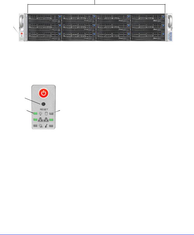
The following figure shows the front panel of the ReadyDATA 5200 with the optional front bezel removed.
1
2
Figure 1. ReadyDATA 5200 front panel
1.Drive bays with disk status LEDs
2.Control panel
The following figure shows the control panel in more detail.
|
1 |
|
|
|
|
||
2 |
|
|
|
|
|
|
|
|
|
|
|
|
|
|
|
|
|
|
|
|
|
|
|
3 |
6 |
||||||
4 |
|
|
|
|
7 |
||
|
|
|
|||||
5 |
|
|
|
8 |
|||
|
|
||||||
|
|||||||
Figure 2. ReadyDATA 5200 control panel
1.Power button
2.Reset button
3.Power LED
4.Ethernet LED
5.Power diagnostic LED
6.Disk activity LED
7.Ethernet LED
8.Information LED
Getting Started
5

NETGEAR ReadyDATA 5200
Each drive bay features a latch that releases the pop-out tray handle, as shown in the following figure.
1
2
Figure 3. Disk tray handle and release latch
1.Disk tray handle
2.Disk tray release latch
WARNING:
No matter how many hard drives are installed in your system, ensure that all drive trays remain in the drive bays to maintain proper airflow.
For more information about adding and replacing disk drives, see Add a Disk on page 23 and
Replace a Disk on page 27.
The ReadyDATA 5200 comes with an front bezel that protects the drive bays with a lockable cover. You can operate the ReadyDATA 5200 with or without the front bezel.
The following image shows a ReadyDATA 5200 with the front bezel installed.
Figure 4. ReadyDATA 5200 with front bezel installed
For more information about installing and removing the front bezel, see Front Bezel on page 20.
Getting Started
6
NETGEAR ReadyDATA 5200
Rear Panel
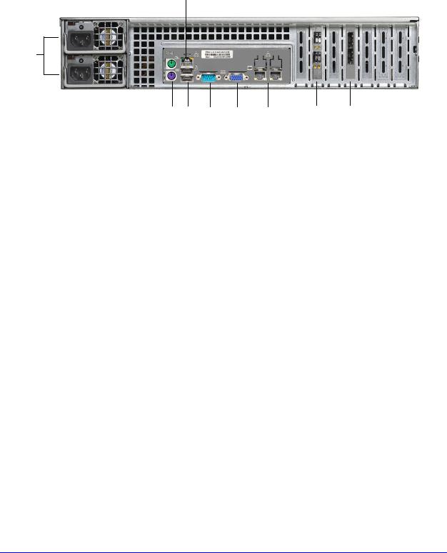
The following figure shows the rear panel of the ReadyDATA 5200. 9
1
2 |
3 |
4 |
5 |
6 |
7 |
8 |
Figure 5. ReadyDATA 5200 rear panel
1.Power supplies
2.PS2 keyboard and mouse ports
3.USB ports
4.RS232 console port
5.VGA monitor port
6.1-gigabit Ethernet ports with status LED status indicators
7.10-gigabit Ethernet ports with status LED status indicators
8.SAS output port
9.Maintenance port
Status and Shutdown
You can obtain information about the status of your unit by reviewing the indicators listed in the following table.
Table 1. Status indicators
Indicator |
Description |
Power LED |
The LED has these states: |
|
• On. The unit is powered on. |
|
• Off. The unit is powered off. |
|
|
Disk activity LED |
The LED has these states: |
|
• On. A disk is active. |
|
• Off. No disk is active. |
|
|
Power diagnostic LED |
The LED has these states: |
|
• On. Power failure |
|
• Off. Normal operation |
Getting Started
7

NETGEAR ReadyDATA 5200
Table 1. Status indicators (continued)
Indicator |
Description |
Information LED |
The LED has these states: |
|
• On. Overheating or fan failure |
|
• Off. Normal operation |
|
|
Disk LEDs on disk tray with |
The top LED indicates disk activity as follows: |
SAS drives or SSD with |
• Blinking. The disk in the bay is active. |
SAS interface |
• On. The disk in the bay is inactive. |
|
|
|
The bottom LED indicates disk failure, as follows: |
|
• Off. Normal operation |
|
• On. Disk failure |
|
|
Disk LEDs on disk tray with |
The top LED indicates disk activity as follows: |
SATA drive or SSD with |
• Blinking. The disk in the bay is active. |
SATA interface |
• Off. The disk in the bay is inactive. |
|
|
|
The bottom LED indicates disk failure, as follows: |
|
• Off. Normal operation |
|
• On. Disk failure |
|
|
Ethernet LEDs (front panel) |
The Ethernet port LEDs have these states: |
|
• Green. An Ethernet cable is connected. |
|
• Blinking. An Ethernet cable is active. |
|
• Off. An Ethernet cable is disconnected. |
|
|
1-gigabit Ethernet port |
The Ethernet port LEDs have these states: |
LEDs (rear panel) |
• Amber. The LAN port is operating at 1 Gbps. |
|
• Green. The LAN port is operating at 100 Mbps. |
|
• Off. The LAN port is operating at 10 Mbps. |
|
|
10-gigabit Ethernet ports |
The Ethernet port LEDs have these states: |
(rear panel) |
• Green. The LAN port is operating at 10 Gbps. |
|
• Amber. The LAN port is operating at 1 Gbps. |
|
|
You can shut down your unit in these ways:
•Using the Power button:
•Preferred shutdown. Press the Power button two times to initiate a graceful shutdown.
•Forced shutdown. If the unit is hung, press the Power button and hold for 5 seconds to force a shutdown.
•Using Dashboard. For information about using Dashboard to shut down your unit, see the ReadyDATA OS Software Manual.
Getting Started
8

NETGEAR ReadyDATA 5200
Boot Menu
Use the boot menu to restart or troubleshoot your ReadyDATA 5200. It has the following boot modes:
•Normal. Initiates a normal boot process, just like booting using the Power button.
•Factory default. Initiates a reboot process that resets the system to factory settings and clears all data.
WARNING:
This boot mode erases all data. If your system has data that you want to save, back it up to another storage device before performing a factory default reboot.
•OS reinstall. Reinstalls the firmware from the internal flash to the disks. Use the OS reinstall boot mode when the system crashes and corrupts some configuration files. OS reinstall boot mode also resets some settings on your unit, such as Internet protocol settings and the administrator password, to defaults.
•Tech support. Boots into a low-level diagnostic mode. Use the tech support boot mode only when instructed to do so by a NETGEAR technical support representative.
•Memory test. Performs a memory test. The pass or fail result is reported using the unit’s LEDs. Contact a NETGEAR technical support representative to interpret memory test results.
To access the boot menu:
1. Power off your unit.
2. With a straightened paper clip, press and hold the Reset button. 3. Press the Power button to power on the unit.
4. Continue to press the Reset button until the power diagnostic LED and the information LED are both lit.
The step takes approximately 1 minute.
5.Release the Reset button.
6.Press the Reset button within 2 seconds to enter the boot menu.
Getting Started
9

NETGEAR ReadyDATA 5200
7.Press and release the Reset button to scroll through the boot menu options.
Watch the blink pattern of the power diagnostic LED and the information LED. The following table shows the how the system displays the current option using the power diagnostic LED and information LED.
Boot Mode |
Power Diagnostic LED and Information LED Blink Pattern |
|||||
|
|
|
|
|
|
|
Normal |
|
|
|
|
|
|
|
|
|
|
|
|
|
Factory default |
|
|
|
|
|
|
|
|
|
|
|
|
|
OS reinstall |
|
|
|
|
|
|
|
|
|
|
|
|
|
Tech support |
|
|
|
|
|
|
|
|
|
|
|
|
|
Memory test |
|
|
|
|
|
|
|
|
|
|
|
|
|
Legend:
•Left: Power diagnostic LED
•Right: information LED
•Off:
•On:
8.When the power diagnostic LED and information LED indicate the correct boot mode, press and hold the Reset button for 3 seconds to select that boot mode.
The system confirms the selection by blinking the power diagnostic LED and the information LED twice, and then begins to boot the system in the selected boot mode.
Getting Started
10
NETGEAR ReadyDATA 5200
Factory Settings
The following table lists factory settings for the ReadyDATA 5200.
Table 2. Factory settings
Feature |
Default |
|
|
|
|
Login |
|
|
|
|
|
|
User login URL when the ReadyDATA |
https://169.254.x.x |
|
5200 is not connected to a DHCP server |
|
|
|
The last two octets are randomly generated based on the |
|
|
system’s MAC address. |
|
|
|
|
Admin user name (case sensitive) |
admin |
|
|
|
|
Admin login password (case sensitive) |
password |
|
|
|
Management |
|
|
|
|
|
|
System configuration |
Dashboard web-based configuration and status |
|
|
monitoring built in to the system’s firmware |
|
|
|
|
Discovery utility |
RAIDar for Windows, Mac, and Linux |
|
|
|
LAN Connections |
|
|
|
|
|
|
MAC address |
See product sticker on top of unit |
|
|
|
|
MTU size |
1500 |
|
|
|
|
Ports |
2 Auto Sense 10/100/1000BASE-T, RJ-45 |
|
|
|
|
LAN IP address |
DHCP acquired |
|
|
|
Getting Started
11

NETGEAR ReadyDATA 5200
Technical Specifications
The following table lists the technical specifications for the ReadyDATA 5200.
Table 3. ReadyDATA 5200 technical specifications
Feature |
Specification |
|
|
|
|
Electrical |
|
|
|
|
|
|
Power supplies (PSU) |
Two 700W server-rated AC power supplies |
|
|
|
|
Input |
100–240V AC, 50/60Hz |
|
|
|
|
Power consumption |
170 W typical with six1 TB disks |
|
|
|
Thermal |
|
|
|
|
|
|
Cooling fans |
Three 80-mm dual ball-bearing chassis cooling fans |
|
|
|
|
Fan failure alerts |
Hardware LED, software using Dashboard and high |
|
|
temperature email alert with auto-shutdown option. |
|
|
|
Operating Environmental |
|
|
|
|
|
|
Temperature |
0°–40° C (32°–10°4 F) |
|
|
|
|
Humidity (non-condensing) |
20%–80% |
|
|
|
Physical |
|
|
|
|
|
|
Form factor |
2U rack mount with 12 hot-swappable SATA, SAS, and |
|
|
SSD drive bays |
|
|
|
|
Dimensions (H x W x D) |
3.5 x 17.2 x 25.5 in. (89 x 437 x 648 mm) |
|
|
|
|
Weight |
38.6 lb (17.5 kg) with no disks installed |
|
|
|
Optional Spare Parts |
|
|
|
|
|
|
Disk tray |
Hot-swappable 3.5-in. and 2.5-in. drive trays |
|
|
|
|
Cooling fan |
80-mm dual ball-bearing chassis cooling fan |
|
|
|
|
PSU |
Hot-swappable 700W PSU |
|
|
|
|
Rack mount |
Sliding rails |
|
|
|
Getting Started
12
 Loading...