


High Light Output Projection System • Großbildschirm Projektions-System
XT9000
User’s Manual • Bedienungshandbuch

XT9000
High Light Output Projection System
User’s Manual
CAUTION: To turn off main power, be sure to remove the plug from power outlet. The power outlet socket should be installed as near to the equipment as possible, and should be easily accessible.
Precautions: Please read this manual carefully before using your NEC XT9000 Projector and keep the manual handy for future reference.
3. GSGV Acoustic Noise Information Ordinance:
The sound pressure level is less than 70 dB(A) according to ISO 3744 or ISO 7779.
WARNING
This is a Class A product. In a domestic environment this product may cause radio interference in which case the user may be required to take adequate measures.
WARNING
TO PREVENT FIRE OR SHOCK HAZARDS, DO NOT EXPOSE THIS UNIT TO RAIN OR MOISTURE. ALSO DO NOT USE THIS UNIT’S POLARIZED PLUG WITH AN EXTENSION CORD RECEPTACLE OR OTHER OUTLETS, UNLESS THE PRONGS CAN BE FULLY INSERTED. REFRAIN FROM OPENING THE CABINET AS THERE ARE HIGH-VOLTAGE COMPONENTS INSIDE. REFER SERVICING TO QUALIFIED SERVICE PERSONNEL.
AVERTISSEMENT
POUR EVITER UN FEU OU UN RISQUE D’ELECTROCUTION NE PAS EXPOSER CET ENSEMBLE A LA PLUIE OU A L’HUMIDITE; DE MEME, NE PAS BRANCHER LA PRISE POLAIRE AVEC UNE RALLONGE A MOINS QUE LES DENTS DE LA PREMIERE NE S’Y INSERENT PLEINEMENT.
EVITER D’OUVRIR LE COFFRET CAR IL Y A, A L’INTERIEUR, DES COMPOSANTS SOUMIS A UNE HAUTE-TENSION; POUR LES REPARATIONS, S’ADRESSER A UN PERSONNEL QUALIFIE.
CAUTION |
RISK OF ELECTRIC SHOCK |
DO NOT OPEN |
CAUTION: TO REDUCE THE RISK OF ELECTRIC SHOCK, DO NOT OPEN COVER. NO USER-SERVICEABLE PARTS INSIDE. REFER SERVICING TO QUALIFIED SERVICE PERSONNEL.
This symbol warns the user that uninsulated voltage within the unit may have sufficient magnitude to cause electric shock. Therefore, it is dangerous to make any kind of contact with any part inside of this unit.
This symbol alerts the user that important literature concerning the operation and maintenance of this unit has been included. Therefore, it should be read carefully in order to avoid any problems.
ATTENTION |
RISQUE D’ELECTROCUTION |
NE PAS OUVRIR |
ATTENTION: POUR EVITER LES RISQUES D’ELECTROCUTION, NE PAS OUVRIR LE COUVERCLE. AUCUN DES ELEMENTS INTERNES NE DOIT ETRE REPARE PAR L’UTILISATEUR. NE CONFIER L’ENTRETIEN QU’A UN PERSONNEL QUALIFIE.
L’éclair fléché dans un triangle équilatéral est destiné à avertir l’utilisateur de la présence, dans l’appareil, d’une zone non-isolée soumise à une haute-tension dont l’intensité est suffisante pour constituer un risque d’electrocution.
Le point d’exclamation dans un triangle équilatéral est destiné à attirer l’attention de l’utilisateur sur la présence d’informations de fonctionnement et d’entretien importantes dans la brochure dccompagnant l’appareil.
DOC compliance Notice
This Class A digital apparatus meets all requirements of the Canadian Interference-Causing Equipment Regulations.
DOC avis de conformation
Cet appareil numérique de la classe A respecte toutes les exigences du Réglement sur le Matériel D’interférence du Canada.
CAUTION
*In order to reduce any interference with radio and television reception use a signal cable with ferrite core attached.
Use of signal cables without a ferrite core attached may cause interference with radio and television reception.
*This equipment has been tested and found to comply with the limits for a Class A digital device, pursuant to Part 15 of the FCC Rules. These limits are designed to provide reasonable protection against harmful interference when the equipment is operated in a commercial environment. This equipment generates, uses, and can radiate radio frequency energy and, if not installed and used in accordance with the installation manual, may cause harmful interference to radio communications.
Operation of this equipment in a residential area is likely to cause harmful interference in which case the user will be required to correct the interference at his own expense.
E – ii

Important Safeguards
These safety instructions are to ensure the long life of your projector and to prevent fire and shock. Please read them carefully and heed all warnings.
Installation
1.Place the projector on a flat, level surface and in a dry area free from dust and moisture.
2.Do not place the projector in direct sunlight, near heaters or heat radiating appliances.
3.Exposure to direct sunlight, smoke or steam could harm internal components.
4.Handle your projector carefully. Dropping or jarring your projector could damage internal components.
5.Do not place heavy objects on top of the projector.
6.If you wish to have the projector installed on the ceiling: a Do not attempt to install the projector yourself.
b The projector must be installed by qualified technicians in order to ensure proper operation and reduce the risk of bodily injury.
c In addition, the ceiling must be strong enough to support the projector and the installation must be in accordance with any local building codes.
d Please consult your dealer for more information. e Do not attempt to stack projectors on the ceiling.
To Dealer or Installer:
To prevent the projector from falling, install it in a place and fasten it in a way with sufficient strength to support the combined weight (107 kg/
236 lb) of the projector (84 kg/185.3 lb), the lens (10 kg/22 lb) and the ceiling mount(13 kg/28.7 lb) for an extended period of time as well as to withstand earthquakes.
Power Supply
1.The projector is designed to operate on a power supply of 2.8 KW
AC200-240V 50/60Hz. Ensure that your power supply fits this requirement before attempting to use your projector.
2.Handle the power cable carefully and avoid excessive bending. A damaged cord can cause electric shock or fire.
3.If the projector will not be used for an extended period of time, disconnect the plug from the power outlet.
4.Placing the power cord and the RGB cable closely to each other can cause beat noise. If this happens, keep the two separated so that beat noise is not generated.
Cleaning
1.Unplug the projector before cleaning.
2.Clean the cabinet periodically with a damp cloth. If heavily soiled, use a mild detergent. Never use strong detergents or solvents such as alcohol or thinner.
3.Use a blower or lens paper to clean the lens, and be careful not to scratch or mar the lens.
Fire and Shock Precautions
1.Ensure that there is sufficient ventilation and that vents are unobstructed to prevent potentially dangerous concentrations of ozone and the build-up of heat inside your projector. Allow at least 8 inches (20cm) of space between your projector and a wall. Allow at least 20 inches (50 cm) of space between the ventilation outlet and object.
2.Prevent foreign objects such as paper clips and bits of paper from falling into your projector. Do not attempt to retrieve any objects that might fall into your projector. Do not insert any metal objects such as a wire or screwdriver into your projector. If something should fall into your projector, disconnect it immediately and have the object removed by a qualified your service person.
3.Do not place any liquids on top of your projector.
CAUTION: High Pressure Lamp May Explode if Improperly Handled. Refer Servicing to Qualified Service Personnel.
Lamp Caution: Please read before operation
Due to the lamp being sealed in a pressurized environment, there is a small risk of explosion, if not operated correctly. There is minimal risk involved, if the unit is in proper working order, but if damaged or operated beyond the recommended 750 hours, the risk of explosion increases.
Please note that there is a warning system built in, that displays the following message when you reach 750 hours of operation” Lamp
Running Time is Over 750 Hours!!” When you see this message please contact your NEC Dealer for a replacement.
If the lamp does explode, smoke will be discharged from the vents located on the side of the unit. This smoke is comprised of glass in particulate form and Xenon gas, and will not cause harm if kept out of your eyes. If your eyes have been exposed to this gas, please flush your eyes out with water immediately and seek immediate medical attention. Do not rub your eyes! This could cause serious injury.
WARNING: Do not look into the lens while the projector is on. Serious damage to your eyes could result.
CAUTION
Do not unplug the power cable from the wall outlet under any one of the following circumstances. Doing so can cause damage to the projector:
•While the message "Please wait a moment" appears. This message will be displayed after the projector is turned off.
•Immediately after the power cable is plugged into the wall outlet (the POWER indicator has not changed to a steady orange glow).
•Immediately after the cooling fan stops working (After the projector is turned off with the POWER OFF button the cooling fan continues to work for 3 minutes while the Two Digit INDICATOR "--" flashes).
E – iii

Recommandations importantes
Ces instructions de sécurité ont pour but d'assurer une longue vieà votre projecteur et d'éviter un incendie ou une décharge électrique. Prière de les lire avec attention et de tenir compte de tous les avertissements.
Installation
1.Placer le projecteur sur une surface plate et de niveau, et dans un endroit sec et à l'abri des poussières et de l'humidité.
2.Ne pas exposer le projecteur aux rayons directs du soleil, ni le placer près d'un chauffage ou de dispositifs de radiation de chaleur.
3.L'exposition aux rayons directs du soleil,à la fumée ou à la vapeur pourrait endommager des composants internes.
4.Manipuler le projecteur avec précautions. Laisser tomber le projecteur ou lui donner des chocs pourrait endommager des composants internes.
5.Ne pas poser d'objets lourds sur le dessus du projecteur.
6.Si vous voulez installer le projecteur au plafond:
a.N’essayez pas d’installer le projecteur vous-même.
b.Le projecteur doit être installé par un technicien qualifié pour garantir une installation réussie et réduire le risque d’éventuelles blessures corporelles.
c.De plus le plafond doit être suffisamment solide pour supporter le projecteur et l’installation doit être conforme aux réglementations locales de construction.
d.Veuillez consulter votre revendeur pour de plus amples informations.
e.Ne pas superposer les projecteurs accrochés au plafond.
A l’attention du revendeur ou de l’installateur:
Afin d’empêcher une chute éventuelle du projecteur, veuillez prendre en compte lors de son placement et de sa fixation de la force nécessaire pour supporter le poids total (107 kg), celui du projecteur (84 kg), de l’objectif (10 kg) et de l’ensemble de fixation au plafond (13 kg), pour de longues périodes et de façon à lui permettre de résister aux tremblements de terre.
Alimentation
1.Le projecteur est conçu pour fonctionner sous une tension d'alimentation de 2,8 KW CA 200-240 V 50/60 Hz. S'assurer que la tension du secteur soit conforme à ces caractéristiques avant d'utiliser le projecteur.
2.Manipuler le cordon d'alimentation avec précautions et éviter des flexions excessives. Un cordon endommagé peut occasionner une décharge électrique ou un incendie.
3.Si le projecteur ne doit pas être utilisé pendant une longue période, débrancher la fiche de la prise de courant.
4.Placer le cordon d'alimentation et le âblec RGB tout près l'un de l'autre peut occasionner un bruit de battement. Si cela se produit, les maintenir séparés jusqu'à ce que le bruit de battement disparaisse.
Nettoyage
1.Débrancher le projecteur avant de le nettoyer.
2.Nettoyer régulièrement le boîtier extérieur avec un chiffon humide. S'il est très sale, utiliser un détergent doux. Ne jamais utiliser de détergent forts ou de solvants tels que de l'alcool ou du diluant.
3.Utiliser un souffleur ou du papier pour objectif pour nettoyer l'objectif, et faire attention de ne pas griffer ou endommager l'objectif.
Précautions contre l'incendie ou la décharge
1.S'assurer qu'il y ait une ventilation suffisante et que les ouvertures ne soient pas obstrué es afin d'éviter des concentrations potentiellement dangereuses d'ozone et l'accumulation de chaleurà l'intérieur du projecteur. Laisser au moins 20 cm d'espace entre le projecteur et un mur. Veuillez laisser un espace libre d’au moins 50 cm (20 pouces) entre les orifices de ventilation et l’objet.
2.Empêcher tous objets étrangers tels que des attaches trombones ou des morceaux de papier de tomber à l'intérieur du projecteur. Ne pas essayer de récupérer des objets qui seraient tombés dans le projecteur. Ne pas introduire d'objets métalliques tels qu'un fil ou un tournevis dans le projecteur. Si quelque-chose doit tomber dans le projecteur, le débrancher immédiatement et faire enlever l'objet par un technicien agréé NEC.
3.Ne pas poser de liquides sur le dessus du projecteur.
ATTENTION: La lampe à haute pression peut exploser si elle est manipulée incorrectement. Confier l'entretienà du personnel d'entretien qualifié.
Précautions avec la lampe : lire avant l'utilisation
La lampe a été scellée dans un environnement sous pression, et il y a donc un petit risque d'explosion, si elle n'est pas utilisée correctement. Le risque est minime si l'appareil est en bon ordre de marche, mais s'il est endommagé ou utilisé au-delà des 750 heures recommandées, le risque d'explosion augmente alors.
Il est à noter l'existence d'un système d'avertissement intégré, lequel affiche le message "Lamp Running Time is Over 750 Hours!! (Le temps de fonctionnement de la lampe a dépassé 750 heures !!)" lorsque les 750 heures de fonctionnement sont atteintes. Lorsque ce message apparaît, prière de contacter son revendeur NEC pour un remplacement.
Si la lampe explose, de la fumée peut être produite par les fentes d'aération situées sur le côté de l'appareil. Cette fumée est composée de verre sous forme de particules et de gaz de Xenon, et n'est pas nuisible si elle est maintenue à distance des yeux. Si les yeux sont exposés à ce gaz, les rincer immédiatement à l'eau courante et consulter tout de suite un médecin. Ne pas frotter les yeux ! Cela pourrait provoquer une grave blessure.
AVERTISSEMENT:
Ne pas regarder dans l'objectif lorsque le projecteur est allumé. De sérieux dommages aux yeux pourraient en résulter.
ATTENTION
Ne pas débrancher le câble d’alimentation de la prise du secteur dans les circonstances suivantes car cela risque d’endommager le projecteur:
•Lorsque le message “Veuillez patientez un instant“apparaît. Ce message sera affiché après que le projecteur soit éteint.
•Immédiatement après que le cordon d'alimentationélectrique ait
été branché sur la prise du mur (l'indicateur POWER n'est pas encore devenu orange).
•Immédiatement après que le ventilateur de refroidissement de soit arrêté de fonctionner. (Après que le projecteur ait été mis hors tension à l’aide du bouton POWER OFF, le ventilateur d’aération continue à tourner durant 3 minutes tandis que le
TÉ MOIN à deux chiffres "--" clignote).
E – iv

LIMITED WARRANTY (USA and Canada only)
NEC Technologies, Inc.(hereafter NECTECH) warrants this product to be free from defects in material and workmanship under the following terms.
HOW LONG IS THE WARRANTY
Parts and labor are warranted for (1) One Year from the date of the first customer purchase. The lamp is warranted for 500 hours of operating time or 90 days, whichever comes first.
Decrease in lamp light output level is not covered by this warranty.
WHO IS PROTECTED
This warranty may be enforced only by the first purchaser.
WHAT IS COVERED AND WHAT IS NOT COVERED
Except as specified below, this warranty covers all defects in material or workmanship in this product. The following are not covered by the warranty:
1.Any product which is not distributed in the U.S.A. or Canada by NECTECH or which is not purchased in the U.S.A. or Canada, from an authorized NECTECH dealer.
If you are uncertain as to whether a dealer is authorized, please contact NECTECH at 800-836-0655.
2.Any product on which the serial number has been defaced, modified or removed.
3.Damage, deterioration or malfunction resulting from:
a.Accident, misuse, abuse, neglect, fire, water, lightning or other acts of nature, unauthorized product modification, or failure to follow instructions supplied with the product.
b.Repair or attempted repair by anyone not authorized by NECTECH.
c.Any shipment of the product (claims must be presented to the carrier).
d.Removal or installation of the product.
e.Any other cause which does not relate to a product defect.
4.Cartons, batteries, external cabinets, magnetic tapes, or any accessories used in connection with the product.
WHAT NEC WILL COVER
We will pay labor and material expenses for covered items, but we will not pay for the following:
1.Removal or installation charges.
2.Costs of initial technical adjustments(set-up), including adjustment of user controls. These costs are the responsibility of the NECTECH dealer from whom the product was purchased.
3.Payment of shipping charges.
HOW YOU CAN GET WARRANTY SERVICE
1.To obtain service on your product, consult the dealer from whom you purchased the product, or ship it prepaid to any authorized NECTECH service center.
2.Whenever warranty service is required, the original dated in voice (or a copy) must be presented as proof of warranty coverage, and should be included in any shipment of the product. Please also include in any mailing, your name, address and a description of the problem(s).
3.For the name of the nearest NECTECH authorized service center, call NECTECH at 800-836-0655.
LIMITATION OF IMPLIED WARRANTIES
All implied warranties, including warranties of merchantability and fitness for a particular purpose, are limited in duration to the length of this warranty.
EXCLUSION OF DAMAGES
NECTECH’s liability for any defective product is limited to the repair or replacement of the product at our option. NECTECH shall not be liable for:
1.Damage to other property caused by any defects in this product, damages based upon inconvenience, loss of use of the product, loss of time, commercial loss; or
2.Any other damages whether incidental, consequential or otherwise. Some states do not allow limitation on how long an implied warranty lasts and/or do not allow the exclusion or limitation of incidental or consequential damages, so the above limitations and exclusions may not apply to you.
HOW STATE LAW RELATES TO THE WARRANTY
This warranty gives you specific legal rights, and you may also have other rights which vary from state to state.
FOR MORE INFORMATION, TELEPHONE 800-836-0655
NEC TECHNOLOGIES, INC.
1250 N. Arlington Heights Road, Suite 500
Itasca. Illinois 60143-1248
NOTE: All products returned to NECTECH for service MUST have prior approval. To get approval, call NEC Technologies at 800-836-0655.
E – v

TABLE OF CONTENTS
INTRODUCTION
Introduction to the XT9000 Projector ..................................... |
E-1 |
Getting Started ....................................................................... |
E-1 |
What's in the Box? ................................................................. |
E-1 |
1. PART NAMES AND FUNCTIONS
Projector ................................................................................. |
E-2 |
Controls ............................................................................ |
E-3 |
Terminal Panel ................................................................. |
E-4 |
Remote Control ...................................................................... |
E-6 |
Remote Control Features ................................................ |
E-6 |
Remote Control Precautions ........................................... |
E-7 |
Remote Control Battery Installation ................................ |
E-7 |
2. INSTALLATION
Setting up Your Projector ....................................................... |
E-8 |
Screen Size and Projection Distance .................................... |
E-8 |
Table of Throw Distance and Screen Sizes |
|
for Optional Lenses ............................................................. |
E-8 |
Lens Shift Adjustable Range ................................................. |
E-9 |
Moving the Projector ............................................................ |
E-10 |
Selecting a Location ............................................................. |
E-10 |
3. SETUP
Connecting the Power Cable and Turning on the Projector ..... |
E-11 |
Set up the Projector ............................................................. |
E-12 |
Keystone ............................................................................... |
E-13 |
Setting up for Double Stacking in Link Mode ...................... |
E-13 |
Projector Orientation ............................................................ |
E-15 |
4. CONNECTIONS
When Used in Standalone Operation .................................. |
E-16 |
When Used with One Switcher (ISS-6020/ISS-6020G) ...... |
E-17 |
When Used with Two or More Switchers (100 Inputs) ........ |
E-18 |
REMOTE 1 Connector ......................................................... |
E-20 |
Operating Multiple Projectors with the Remote Control ...... |
E-22 |
Using the RGB DIGITAL Connectors ................................... |
E-23 |
5. OPERATION
General Controls .................................................................. |
E-24 |
Using the Menus .................................................................. |
E-24 |
Shutter Mechanism .............................................................. |
E-24 |
A List of Direct Key Combinations ....................................... |
E-25 |
Menu Tree ............................................................................. |
E-26 |
Menu Elements .................................................................... |
E-28 |
Menu Descriptions & Functions ........................................... |
E-29 |
Source Select ....................................................................... |
E-29 |
Switcher ......................................................................... |
E-29 |
Entry List ........................................................................ |
E-29 |
Entry Edit Command ............................................... |
E-29 |
Adjust (Source) .................................................................... |
E-30 |
Picture ............................................................................ |
E-30 |
Brightness ................................................................ |
E-30 |
Contrast ................................................................... |
E-30 |
Saturation ................................................................ |
E-30 |
Color ........................................................................ |
E-30 |
Hue .......................................................................... |
E-30 |
Sharpness ............................................................... |
E-30 |
V-Aperture ............................................................... |
E-30 |
Gamma Correction .................................................. |
E-30 |
White Balance ................................................................ |
E-30 |
Color Temperature ................................................... |
E-30 |
Brightness R/G/B ..................................................... |
E-30 |
Contrast R/G/B ........................................................ |
E-30 |
Signal Level ............................................................. |
E-30 |
Image ............................................................................. |
E-30 |
Pixel Adjust .............................................................. |
E-30 |
Clock/Phase .......................................................... |
E-30 |
Horizontal/Vertical Position ..................................... |
E-31 |
Aspect Ratio ............................................................ |
E-31 |
Resolution ................................................................ |
E-31 |
Overscan ................................................................. |
E-31 |
Video Filter .............................................................. |
E-31 |
Blanking ................................................................... |
E-31 |
Video Adj ........................................................................ |
E-31 |
Noise Reduction ...................................................... |
E-31 |
Color Matrix ............................................................. |
E-32 |
Y/C Delay ................................................................. |
E-32 |
Telecine ................................................................... |
E-32 |
Motion Select ........................................................... |
E-32 |
Motion Level ............................................................ |
E-32 |
YTR Adjustment ...................................................... |
E-32 |
CTR Adjustment ...................................................... |
E-32 |
Option Adj ...................................................................... |
E-32 |
Clamp Timing ........................................................... |
E-32 |
Sync Protection ....................................................... |
E-32 |
VD Delay .................................................................. |
E-32 |
Lens Memory ................................................................. |
E-33 |
Switcher ......................................................................... |
E-33 |
Switcher Gain .......................................................... |
E-33 |
Volume ..................................................................... |
E-33 |
Ref Adj .................................................................................. |
E-33 |
Keystone ........................................................................ |
E-33 |
Lamp .............................................................................. |
E-34 |
Lamp Mode .............................................................. |
E-34 |
Reference White Balance .............................................. |
E-34 |
Factory Default ..................................................................... |
E-34 |
Projector Options ................................................................. |
E-34 |
Timer .............................................................................. |
E-34 |
On/Off Timer ............................................................ |
E-34 |
Sleep Timer ............................................................. |
E-35 |
Menu .............................................................................. |
E-35 |
Menu Mode/Language/Menu Display Time/ |
|
Display Select/Date Format/Date, Time Preset .... |
E-35 |
Setup .............................................................................. |
E-36 |
Page 1: |
|
Orientation/Background/S-Video Mode Select . E-36 |
|
Page 2: |
|
Signal Select(RGB1/2) /Sync Termination |
|
(RGB 1/2) .......................................................... |
E-36 |
Page 3: |
|
Signal Select (Video 1/2, S-Video 1/2 and Switcher) E-36
Page 4: |
|
Auto Adjust (RGB Only)/Power Management/ |
|
Power Off Confirmation ..................................... |
E-36 |
Keystone Save/Lens Memory/ |
|
User Name ........................................................ |
E-37 |
Page 5: |
|
Communication Speed/Projector ID / |
|
Default Source Select ........................................... |
E-37 |
Link Mode ...................................................................... |
E-37 |
Switcher Control ............................................................ |
E-37 |
PC Card Files ....................................................................... |
E-38 |
Help ...................................................................................... |
E-38 |
Contents ......................................................................... |
E-38 |
Source Information ........................................................ |
E-38 |
Source Name/Input Terminal/Entry No./
Horizontal & Vertical Frequency/Sync Polarity/Signal Type/ Video Type/ Sync Type/ Interlace/Resolution/Direct Key/
Aspect Ratio/ Gamma Correction/Noise Reduction/Color Matrix/
Matrix Type |
|
Projector Information ..................................................... |
E-38 |
User Name/Serial Number/Lamp Hour Meter/ Projector Usage/ |
|
Projector ID/Version/Bios/Firmware/Data/SUB-CPU/ |
E-38 |
Formatter Version ................................................................ |
|
Link Mode ................................................................ |
E-39 |
Test Pattern .......................................................................... |
E-39 |
Cross Hatch,Gray Bars,Color Bars,Black Raster,GrayRaster,White Raster, |
E-39 |
ANSI Checker,Focus,Aspect Ratios (Red/Green/Blue) ........................ |
|
Selecting a new signal that is close to one of hte listed |
|
signals in horizontal and vertical frequency ........................ |
E-39 |
6. SPECIFICATIONS ............................................. |
E-40 |
7. Optional Accessories ...................................... |
E-42 |
XT SDI BOARD .................................................................... |
E-42 |
REMOTE 3 (XLR) Pin Assignments and Signals ................ |
E-42 |
8. Compatible Input Signal List ........................... |
E-43 |
9. List of Menu Items Available on Link Mode ..... |
E-44 |
Appendix ............................................................. |
E-45 |
Dimensions ........................................................................... |
E-45 |
Tips on Adjusting Focus for Lens Memory Function ........... |
E-46 |
E – vi

INTRODUCTION
This section introduces you to your new XT9000 Projector, provides a list of materials that comes with your projector and describes the features and controls.
Introduction to the XT9000 Projector
The XT9000 is one of the finest, most technically advanced projectors available today.The XT9000 enables you to project exceptionally bright, precise images up to 500 inches across (measured diagonally) from your PC or Macintosh computer (desktop or notebook), VCR, document camera, laser disc player, DVD player and even an HD VCR or HD laser disc player.
You can use the projector on a tabletop or cart, you can permanently mount it on a ceiling*, or you can use the projector to project images from behind the screen. The remote control can be used in a wired or wireless configuration.
Features you'll enjoy :
•A high-performance 2.0 KW Xenon lamp that delivers 8000 ANSI lumens with a lamp life of 750 hours.
•NEC’s unique DLPTM based light engine offers true color reproduction.
•The XT9000 can accommodate any picture size from 80 to 500 inches (measured diagonally).
•The XT9000 projects images with uniform brightness while colors remain true to their original source.
•The projector can be double stacked without an external frame, producing bright images of 16,000 ANSI lumens. In addition, double stacking offers built-in redundancy.
•An image can be projected from in front or behind a screen, and the projector can even be installed on the ceiling*.
•Supports RGB digital, HDTV and DVD signals as well as most IBM
VGA, S-VGA, XGA, SXGA, UXGA (scaling), Macintosh or any other RGB signals within a horizontal frequency range or 15 to 107 kHz and a vertical frequency range of 24 to 120 Hz. This includes NTSC3.58, PAL, PAL60, SECAM, NTSC4.43, Y/C and 1080p, 1080i,
720p and 480p HDTV standard video signals.
•Built-in telecine detection enables 3:2 pull-down correction with no external processing necessary, eliminating jitter and artifacts to allow for original film source motion quality.
•A newly designed menu system provides for easy setup and operation of the projector.
•The remote control can be used wired or wireless.
*Installing the projector on the ceiling must be done by authorized
NEC technicians.
Consult your NEC dealer for more information.
Digital Light Processing and DLP are trademarks of Texas Instruments.
Getting Started
The fastest way to get started is to take your time and do everything right the first time. Taking a few minutes now to review the manual may save you hours later on. At the beginning of each section of the manual you'll find an overview. If the section doesn't apply, you can skip it.
What's In The Box?
Make sure your box contains everything listed. If any pieces are missing, contact your dealer. Please save the original box and packing materials if you ever need to ship the projector.
•XT9000 Projector
•Remote Control with Remote Cable (wireless/wired).
•DVI-D Cable
•Power Cable (single phase)
•Two AA Batteries
•User Manual
•CompactFlash Memory Card (8MB) with Adapter
E – 1
1. Part Names and Functions
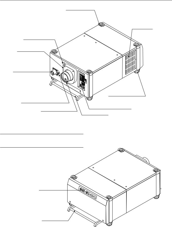
Stacking Pad (4 pcs)
Ventilation (out)
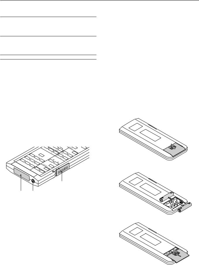
Remote Sensor
PC Card Slot
Insert a PC memory card here to upgrade the projector system software or copy data. To access the slot, loosen the screw.
AC INPUT
Connect the supplied power cable here (AC 200-240V).
Foot
Power Switch (Main power)*
Input Terminal Panel
Lens (Optional)
Carrying Handle
*To turn on the main power to the projector, press the switch to the ON position (I) and the POWER indicator on the rear panel will turn orange in color.
Press to the OFF position (0) to turn the main power off.
NOTE: When turning off the main power, first return the projector to the standby condition by pressing the POWER OFF button on the remote control or the POWER button on the rear panel and then turn off the main POWER switch. These procedures are necessary to protect your projector and the connected equipment.
Controls
Carrying Handle
E – 2
Controls
11 |
10 |
9 |
8 |
7 |
5 |
4 |
2 |
Remote sensor |
LENS SHIFT FOCUS ZOOM MENU
 -
-
SELECT |
ENTER |
INDICATOR |
POWER |
|
|
ON |
ON/OFF |
|
+ |
|
|
|
|
|
|
|
|
OFF |
|
|
CANCEL |
|
STATUS |
|
|
|
6 |
3 |
1 |
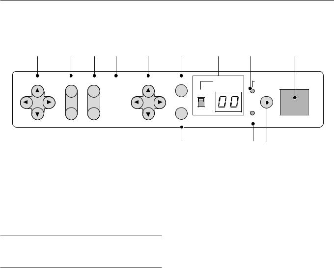
1. Power Button
Press to turn the projector on when the projector is in the standby condition (Main Power switch must be on and the POWER indicator lit orange). Press and hold for 2 seconds to turn off the projector.
2. Power Indicator
When this indicator is green, the projector is on; when the indicator is orange, it is in standby mode.
NOTE: After the projector is turned off, the indicator "--" flashes for three minutes to show that the cooling fan is working.
Do not turn off the main power during that time. After "--" stops flashing, the POWER indicator will change to a steady amber glow and the projector will be in the stand-by mode.
3. Status Indicator
When the On Timer is set and the projector is in the standby mode, the Status indicator flashes green to show that the On Timer program is active.
4. Two Digit Display
During normal operation the current projector ID (address) is shown in this two digit display. In the event of an error, a projector error code will be displayed.The display can be turned off using the ON/OFF Switch to the left of the display.
5. Enter Button
Executes your menu selection and activates items selected from the menu. When the slidebar or dialog box is displayed:
Pressing this button confirms adjustments/setting and returns to the previous menu display.
6. Cancel Button
Press this button to exit the menu. Press this button to return the adjustments to the last condition while you are in the adjustment or setting menu.
7. Select (Up/Down/Left/Right) Button
Up/Down: Use these buttons to select the menu of the item you wish to adjust.
Left/Right: Use these buttons to change the level of a selected menu item.
8. Menu Button
Displays the main menu for operation.
9. Zoom Button
Zoom the lens in and out.
10.Focus Button
Adjust the lens focus.
11.Lens Shift Button
Adjust the lens offset by shifting the projected image position horizontally and vertically.
E – 3
Terminal Panel
|
5 |
|
|
|
|
|
RGB DIGITAL |
|
|
|
|
OUTPUT |
|
INPUT9 |
|
|
|
|
|
|
|
|
6 |
INPUT3 |
INPUT2 |
INPUT1 |
INPUT4 |
|
7 |
RGB |
R/Cr |
R/Cr |
Cr |
|
|
1 |
|
|
|
|
|
|
G/Y |
G/Y |
Y |
|
OUTPUT |
|
|
|
|||
OPTION |
|
|
|
|
|
IN |
|
|
|
|
|
|
B/Cb |
B/Cb |
Cb |
SDI |
For the optional XT SDI board. |
2 |
|
|
|
|
|
OUT |
|
|
|
|
|
|
H/HV |
H/HV |
|
|
INPUT0 |
|
|
|
|
|
|
REMOTE1 |
V |
V |
|
|
8 |
|
|
|
|||
3 |
|
|
|
|
|
REMOTE2 |
S-VIDEO1 |
INPUT5 |
INPUT6 |
|
9 |
Y |
VIDEO1 |
VIDEO2 |
|
||
|
|
|
|||
IN |
|
|
|
|
|
4 |
C |
|
|
|
10 |
OUT |
|
|
S-VIDEO2 |
|
|
|
|
|
|
||
|
INPUT7 |
INPUT8 |
|
|
|
REMOTE3 |
|
|
|
11 |
|
OUT |
IN |
|
|
|
|
|
|
|
|
||
|
|
LED |
|
|
|
|
|
|
ON |
|
12 |
|
|
|
OFF |
|
|
|
|
|
|
|
|
13 |
|
|
|
|
|
|
|
|
|
|
E – 4 |

1. INPUT 3 RGB Connector (Mini D-Sub 15 pin)
Connect your PC or other analog RGB equipment such as a high-defi- nition document camera.
This connector accepts RGB signals only.
Not compatible with component signals.
2.Option Connector (Mini D-Sub 9 pin)
For system expansion such as PC-control.
IN ................. connect to the external equipment such as PC or Third Party Control System.
OUT ............. for daisy-chaining multiple projectors and operating them with the same external equipment. To do so, connect to a second projector's IN terminal to relay the input at the IN terminal of the first projector until all the projectors are connected.
3.REMOTE 1 Connector (Mini D-Sub 15 pin)
This terminal allows external control of the projector from either the
Switcher or from an external control. When the Switcher is used, connect to the REMOTE 1 terminal on the back of the Switcher.
NOTE: This projector is compatible with the ISS-6020 Switcher.
4. REMOTE 2 Jacks
IN ................. |
wired remote control input. |
OUT ............. |
for daisy-chaining multiple projectors and operating them with |
|
the same remote control. To do so, connect to a second pro- |
|
jector' s IN terminal to relay the input at the IN terminal of the |
|
first projector until all the projectors are connected. |
5.RGB Digital Input/Output Connectors (DVI-D 24 pin)
These connectors are used for double stacking.
Use the supplied DVI-D cable to connect the OUTPUT terminal of the first projector to the second projector's INPUT until all the projectors are connected.
The output is TMDS non-perfect.
The output connector is used for stacking.
6.INPUT 1 and INPUT 2 Terminals (BNC)
Connect R,G,B,H (Horizontal sync) and V (Vertical sync) outputs of the external equipment such as the Switcher. If using a component with a combined sync (SYNC) output, connect it to the H/V terminal.
Also connect component video outputs (Y/Cb/Cr) of the external equipment such as DVD player.
NOTE: The INPUT 2 terminal does not support SW1 Level and SW2 Level modes for the ISS-6020 switcher.
7. INPUT 4 Y/Cb/Cr Terminal (RCA)
Connect component video outputs (Y/Cb/Cr, Y/Pb/Pr) of the external equipment such as DVD player.
NOTE: This terminal accepts component signals only.
8. INPUT 5 VIDEO 1 Terminal (BNC)
Connect to the BNC video output of the external equipment such as a VCR or laser disc player.
9. INPUT 6 VIDEO 2 Terminal (RCA)
Connect to the RCA video output of the external equipment such as a
VCR or laser disc player.
10. INPUT 8 S-VIDEO 2 Terminal (Mini DIN 4 pin)
Connect to the S-video output of the external equipment such as a
VCR with an S-video output. This terminal allows switching between S2 and S1 VIDEO input modes. See the "S-Video Mode Select" section on page E-36 for more information.
11. INPUT 7 S-VIDEO 1 Terminal (BNC)
Connect to the Y/C separate BNC video outputs of the external equipment such as a VCR or laser disc player.
12. LED Switch
Lights up the panel on both the front and the rear at the same time.
13. REMOTE3 Connectors (XLR Connectors)
Connect an extension cable such as an audio cable to control two projectors or more using the remote control. See page E-42 for the pin
assignments. |
|
IN ................. |
wired remote control input. |
OUT ............. |
for daisy-chaining multiple projectors and operating them with |
|
the same remote control. To do so, connect to a second pro- |
|
jector' s IN terminal to relay the input at the IN terminal of the |
|
first projector until all the projectors are connected. |
E – 5
Remote Control |
|
|
|
|
|
7 ADJUST PICTURE |
|
|
|
|
|
|
||||||
|
|
|
|
|
Press to display the Picture adjustment screen. Pressing this button |
|||||||||||||
|
|
|
|
|
|
|
|
|
||||||||||
|
|
|
|
|
|
|
|
|
sequentially selects "Brightness" → "Contrast" → "Saturation" → |
"Color" |
||||||||
|
|
|
|
|
|
|
|
27 |
→ |
"Hue" → |
"Sharpness" → |
"V-Aperture" → |
"Gamma Correction". |
|||||
|
|
|
|
|
|
|
|
|
8 IMAGE/PROJECTOR |
|
|
|
|
|
||||
2 |
|
|
|
|
|
|
|
|
Press to display the Image Option screen. Pressing this button sequen- |
|||||||||
|
|
|
|
|
|
|
|
tially selects "Pixel Adjust" → |
"Position" → "Aspect Ratio" → |
"Resolu- |
||||||||
|
|
POWER |
|
|
INPUT |
|
|
tion" → |
"Overscan" → |
"Video Filter" → |
"Blanking". |
|
|
|||||
1 |
|
ON |
OFF |
1 ABC |
|
2 DEF |
3 GHI |
|
While pressing and holding CTL, pressing this button rotates "On/Off |
|||||||||
|
|
|
|
|
|
|
|
Timer" → |
"Sleep Timer" → |
"Menu" → |
"Setup" → |
"Link Mode" → |
||||||
13 |
|
TEST |
|
4 JKL |
|
5MNO |
6 PQR |
|
"Switcher Control". |
|
|
|
|
|
|
|||
|
|
|
|
|
|
|
9 |
|
|
|
|
|
|
|
|
|
|
|
28 |
|
IMAGE/ PROJECTOR |
7 STU |
|
8 VWX |
9 YZ/ |
9 INPUT |
|
|
|
|
|
|
|
||||
ON |
|
|
|
|
|
|
|
|
|
|||||||||
8 |
|
|
|
|
|
|
|
Use to select an input, to name a signal, or to enter a passcode during |
||||||||||
|
|
|
|
|
|
|
|
|||||||||||
7 |
OFF |
PICTURE WHITE BAL. |
|
|
0 |
|
|
input registration. |
|
|
|
|
|
|
||||
|
|
|
|
|
|
|
1--INPUT 1 for RGBHV/Y, Cb/Pb, Cr/Pr |
|
|
|
|
|||||||
|
|
|
|
|
|
|
|
|
|
|
|
|||||||
6 |
|
ADJUST |
|
|
|
|
23 |
2--INPUT 2 for RGBHV/Y, Cb/Pb, Cr/Pr |
|
|
|
|
||||||
22 |
|
|
|
|
|
|
|
14 |
3--INPUT 3 for RGB |
|
|
|
|
|
|
|||
|
KEY ST./ R AMP/ G |
E-LIST/ B |
HELP |
INFO |
|
4--INPUT 4 for Y, Cb/Pb, Cr/Pr |
|
|
|
|
||||||||
21 |
|
|
|
|
|
|
|
12 |
5--INPUT 5 for VIDEO 1 |
|
|
|
|
|
||||
15 |
|
PIXEL |
POSI/ LENS |
PICT/ SHUT SOUND |
OSD |
|
6--INPUT 6 for VIDEO 2 |
|
|
|
|
|
||||||
|
|
|
|
|
|
|
19 |
7--INPUT 7 for S-VIDEO 1 |
|
|
|
|
|
|||||
17 |
|
|
|
|
|
|
|
|
|
|
|
|
||||||
|
AUTO |
|
|
|
MUTE |
|
18 |
8--INPUT 8 for S-VIDEO 2 |
|
|
|
|
|
|||||
16 |
|
|
|
|
|
|
|
9--INPUT 9 for RGB DIGITAL input |
|
|
|
|
||||||
|
|
|
|
|
|
|
20 |
|
|
|
|
|||||||
|
|
MENU/ ADDRESS |
|
|
|
0--INPUT 0 for SDI input on the optional SDI board |
|
|
||||||||||
3 |
|
|
|
|
|
|
|
5 |
10 UNDO |
|
|
|
|
|
|
|
||
|
|
UNDO |
|
|
|
ENTER |
|
|
|
|
|
|
|
|
||||
10 |
|
|
|
|
|
|
|
|
Press to return the adjustments and settings to the previous condition. |
|||||||||
|
|
|
|
|
|
|
|
While pressing and holding CTL, pressing this button clears all the menus |
||||||||||
|
|
|
CANCEL |
|
|
|
|
4 |
||||||||||
|
|
|
|
|
|
|
or adjustment/setting screen. At this time the adjustments/settings are |
|||||||||||
11 |
|
|
|
|
|
|
|
|||||||||||
|
|
|
|
|
|
|
|
stored in memory. |
|
|
|
|
|
|
||||
|
|
|
FOCUS + |
MAGNIFY/ ZOOM + |
|
|
|
|
|
|
|
|||||||
|
|
|
|
|
|
|
|
|
|
|
|
|
|
|||||
|
|
CTL |
|
- |
|
|
- |
25 |
11 CANCEL |
|
|
|
|
|
|
|||
26 |
|
|
|
|
Press to exit the menu. |
|
|
|
|
|
||||||||
|
|
|
|
|
|
|
|
|
|
|
|
|
||||||
|
|
|
|
|
|
|
|
Press this button with CTL to return to the previous menu while the |
||||||||||
|
|
|
|
|
|
|
|
|
||||||||||
|
|
|
|
|
|
|
|
24 |
menus appear. This feature allows you to adjust several items concur- |
|||||||||
|
|
|
|
|
|
|
|
rently. |
|
|
|
|
|
|
|
|
||
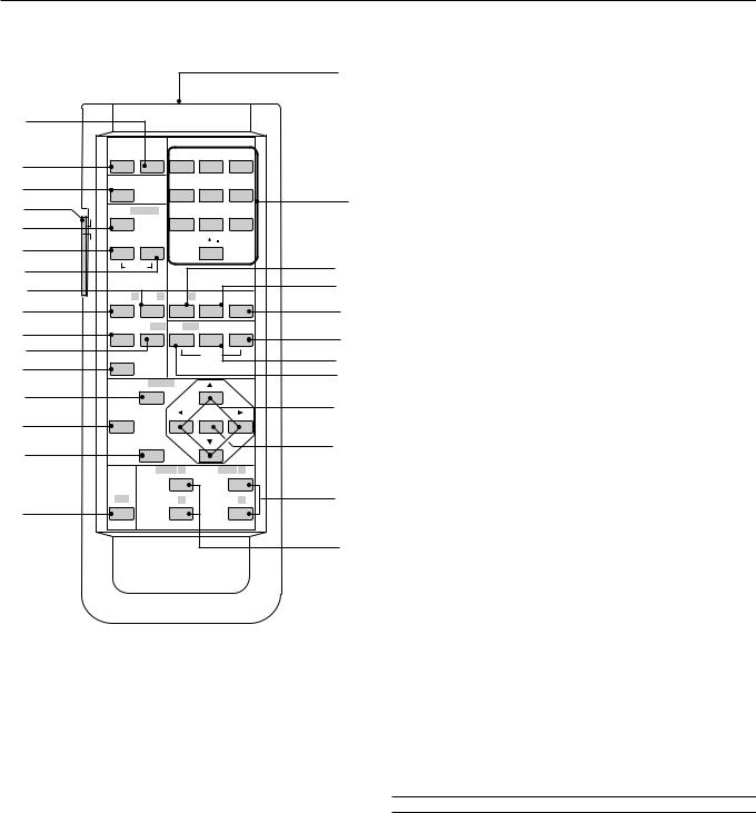
1 POWER ON
Press to turn on the projector. The POWER indicator lights up green.
2 POWER OFF
Press and hold this button for a minimum of two seconds to turn off the projector.
3 MENU
Press to display the main menu.
While pressing and holding CTL, press this button to display the Remote Control ID dialog box to specify the remote control ID.
4 ENTER
Executes the menu selection and activates items selected from the menu. When the slidebar or dialog box is displayed:
Pressing this button confirms adjustments/setting and returns to the previous menu display.
5 SELECT (Up/Down/Left/Right)
When pressed together, the CTL and buttons work as a Back Space key in the entry screen.
Pressing and holding CTL, then this button moves the menu, slidebar or dialog box.
6 ADJUST WHITE BAL
Press to display the Color adjustment screen. Pressing this button sequentially selects "Color Temperature" → "White Balance - Brightness"
→ "White Balance - Contrast" → "Signal Level" → "Ref.White Bal" →
"Switcher-Gain".
12 INFO
Displays the "Source Information" or "Projector Information" window.
This button toggles between these two windows.
13 TEST
Press to display the test pattern. Pressing this button sequentially selects nine test patterns.
14 HELP
Provides online help.
15 PIXEL
Displays the Pixel Adjust screen to adjust the clock and phase.
16 AUTO (RGB only)
Press to adjust Position-H/V and Pixel Clock for an optimal picture.
NOTE: The Pixel Phase is not available.
17 POSITION
Press to display the Blanking screen; press again to display the Position screen.
While pressing and holding CTL, pressing this button displays the Lens Shift adjustment screen.
18 MUTE SOUND
(available only when using with the ISS -6020 or IPS4000)
Turns off the sound for a short period of time. Press again to restore the sound.
E – 6
19 MUTE OSD
Press to turn off the on-screen display. Press again to restore the onscreen display.
NOTE: You can also turn off the on-screen display by pressing and holding CTL and then pressing MUTE OSD; doing this again restores it. In this case any adjustment will still change the projector's memory settings. This mode is available even when an input is switched to another or the power is turned off using the POWER OFF button on the remote control.
20 MUTE PICTURE
Press to turn off the picture for a short period of time. Press again to restore the picture. Pressing and holding CTL, then pressing this button shuts off the light completely.
NOTE: This is also considered the LENS SHUTTER.
21 KEYSTONE (R)
Press to display the Keystone Correction screen.
22 AMPLITUDE (G)
Service personnel only.
23 ENTRY LIST (B)
Press to display the Entry List screen.
24 FOCUS (+/–)
While pressing and holding CTL, pressing this button allows you to adjust the lens focus.
25 MAGNIFY/ZOOM (+/–)
Magnify the size of a target portion.
While pressing and holding CTL, pressing this button allows you to zoom the lens in and out.
26 CTL
Used in conjunction with other buttons, similar to a shift key on a computer.
|
|
/ |
|
|
|
YZ |
9 |
|
|
|
|
|
PQR |
|
VWX |
|
6 |
|
8 |
GHI |
3 |
MNO |
|
|
|
|
|
Remote Control Precautions
•Use the remote control within a distance of about 7m (23feet) and at an angle of 30˚ above, below, to the left and to the right of the remote control sensor located at the front of the main unit.
•The remote control system may not function when direct sunlight or strong illumination strikes the remote control sensor of the main unit, or when there is an obstacle in the path.
•When remote control buttons are pressed and held, main unit function keys may not operate.
•Do not subject to strong shock.
•Do not allow water or other liquid to splash on the remote control. If the remote control gets wet, wipe it dry immediately.
•Avoid exposure to heat and steam.
•Remove the batteries from the remote control when the remote control is not going to be used for a long period.
You cannot operate the projector using the remote control if:
•the remote ID is not set to [00].
•the remote ID is not the same as the projector ID.
See page E-22 for setting remote ID and page E-37 for setting projector ID.
Remote Control Battery Installation
Installing the Remote Control Batteries
When it comes time to replace the batteries, two "AA" type will be required.
1. Press and open the cover.
2.Align and insert the batteries according to the (+) and (-) indications inside the case.
28
29 27
27 Remote Jack
Connect your remote control cable here for wired operation.
28 Backlight Switch
When using the remote control wirelessly:
Turns the backlight on and off. If no button operation is made within 30 3. Replace the cover. seconds with the Backlight ON, the Backlight will turn off to conserve
battery life.
When using as the wired remote control:
The light stays on in standby and power-on.
29 Infrared Transmitter
Direct the remote control toward the remote sensor on the projector cabinet.
E – 7
2. INSTALLATION
This section describes how to set up your projector and how to connect video and audio sources.
Setting Up Your Projector
Your Projector is simple to set up and use. But before you get started, you must first:
1.Determine the image size
2.Set up a screen or select a non-glossy white wall onto which you can project your image.
3.Install the optional lens to the projector.
NOTE: The lens must be installed by service personnel only.
4.Connect the supplied power cable.
5.Set up the projector.
6.Connect a PC, VCR, DVD player, or other equipment.
7.Make settings or adjustments on the projector.
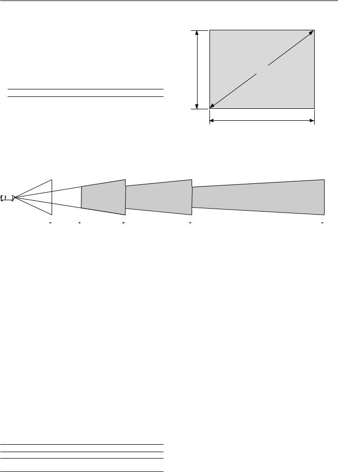
Throw Distance
Screen Size and Projection Distance
Applicable lens and throw distance/ List of screen sizes
Height |
Screen size (Diagonal) |
(V) |
|
Width (H)
Formulas: Screen width H (m) = Screen Diagonal x 4/5 x 0.0254
Screen height V (m) = Screen Diagonal x 3/5 x 0.0254
Screen width H (inch) = Screen size x 4/5 Screen height V (inch) = Screen size x 3/5
|
|
|
|
|
|
|
|
|
|
|
|
|
|
|
|
|
|
|
TL-2Z (H x 2.5) – (H x 4.0) |
|
TL-4Z (H x 4.0) – (H x 7.0) |
|
|
|
|
|
|
|
|
|
|
|
|
||
|
|
|
|
|
|
|
|
|
|
||
|
|
|
|
|
|
|
|
|
|
||
|
|
|
|
|
|
|
|
|
|
||
|
|
TL-08SF (H x 0.84) |
TL-1ZH (H x 1.5) – (H x 2.5) |
|
|
|
|
||||
Table of Throw Distances and Screen Sizes for Optional Lenses |
|
|
|
Unit: m (inch) |
||||||||||
|
|
|
|
|
|
|
|
|
|
|
|
|
|
|
|
Screen Size (4:3) |
SF Fixed Lens |
|
|
|
|
|
Zoom Lens |
|
|
|
|||
|
|
|
|
|
|
|
|
|
|
|
|
|||
|
|
|
|
TL-08SF |
|
TL-1ZH |
|
|
TL-2Z |
|
TL-4Z |
|||
Diagonal |
|
Width (W) |
Height (V) |
0.84:1 |
|
1.5-2.5 |
|
|
2.5 |
- 4.0 |
|
4.0-7.0 |
||
80" |
|
1.6 (64) |
1.3(48) |
1.3 (52.5) |
2.4 (94) |
- 3.9 (156) |
4.0 |
(157) |
- 6.3 (249) |
6.4 |
(250) - 11.1 (437.5) |
|||
|
|
|
|
|
|
|
|
|
|
|
|
|||
100" |
|
2.0 (80) |
1.6(60) |
1.7 (65.6) |
3.0 |
(118) - 4.9 (195) |
5.0 |
(196) |
- 7.9 (312) |
8.0 |
(313) - 13.8 (546.8) |
|||
120" |
|
2.4 (96) |
1.9(72) |
2.0 (78.8) |
3.6 (141) - 5.9(234) |
6.0 |
(235) |
- 9.5 (375) |
9.6 |
(375) - 16.6 (656.2) |
||||
|
|
|
|
|
|
|
|
|
|
|
|
|||
150" |
|
3.0 (120) |
2.4(90) |
2.5 (98.4) |
4.5 |
(176) - 7.4 (292) |
7.5 |
(293) |
- 11.9 (468) |
12.0 (469) |
- 20.8 (820.3) |
|||
|
|
|
|
|
|
|
|
|
|
|
|
|||
180" |
|
3.6 (144) |
2.9(108) |
3.0 (118.1) |
5.4 |
(211) - 8.9 (351) |
9.0 |
(352) |
- 14.2 (562) |
14.3 (563) |
- 25.0 (984.3) |
|||
210" |
|
4.2 (168) |
3.3(126) |
3.5 (137.8) |
6.3 (247) |
- 10.4 (410) |
10.5 |
(411) |
- 16.6 (656) |
16.7 |
(657) - 29.1 (1148.4) |
|||
|
|
|
|
|
|
|
|
|
|
|
|
|||
240" |
|
4.8 (192) |
3.8(144) |
4.0 (157.5) |
7.2 (282) |
- 11.9 (468) |
12.0 |
(469) |
- 19.0 (749) |
19.1 |
(750) - 33.3 (1312.5) |
|||
|
|
|
|
|
|
|
|
|
|
|
|
|||
270" |
|
5.4 (216) |
4.3(162) |
4.5 (177.2) |
8.1 (317) |
- 13.3 (527) |
13.4 |
(528) |
- 21.4 (843) |
21.5 |
(844) - 37.5 (1476.5) |
|||
300" |
|
6.0 (240) |
4.8(180) |
5.0 (196.9) |
9.0 (352) |
- 14.8 (585) |
14.9 |
(586) |
- 23.8 (937) |
23.9 |
(938) - 41.6 (1640.6) |
|||
350" |
|
6.9 (280) |
5.6(210) |
5.8 (229.7) |
10.5 |
(411) - 17.3 (683) |
17.4 |
(684) |
- 27.7 (1093) |
27.8 (1094) - 48.6 (1914) |
||||
|
|
|
|
|
|
|
|
|
|
|
|
|||
400" |
|
7.9 (320) |
6.4(240) |
6.7 (262.5) |
12.0 |
(469) - 19.8 (781) |
19.9 |
(782) |
- 31.7 (1249) |
31.8 (1250) |
- 55.5 (2187.5) |
|||
450" |
|
8.9 (360) |
7.1(270) |
7.5 (295.3) |
13.4 |
(528) - 22.3 (878) |
22.4 |
(879) |
- 35.7 (1406) |
35.8 (1407) |
- 62.5 (2460.9) |
|||
|
|
|
|
|
|
|
|
|
|
|
|
|||
500" |
|
9.9 (400) |
7.9(300) |
8.3 (328.1) |
14.9 |
(586) - 24.8 (976) |
24.9 |
(977) |
- 39.6 (1562) |
39.7 (1563) |
- 69.4 (2734.3) |
|||
For screen sizes between 80” and 500” not indicated on the above table, use formulas below.
Projection Distance = Screen Width (H) x Lens Magnification
Throw distance for TL-08SF lens =H x 0.84
Throw distance for TL1ZH lens =H x 1.5 - H x 2.5
Throw distance for TL2Z lens =H x 2.5 - H x 4.0
Throw distance for TL4Z lens =H x 4.0 - H x 7.0
NOTE: Distances may vary +/- 5%.
NOTE: Do not use another optional lens TL-1Z on XT9000.
Doing so will not deliver the performance of the projector.
E – 8
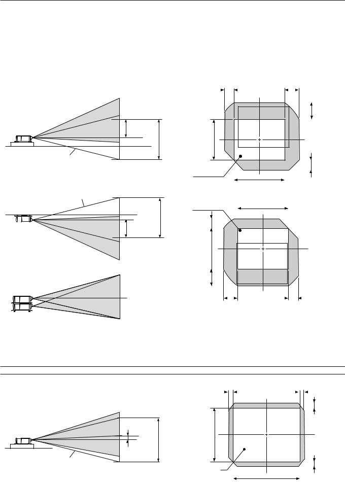
Lens Shift Adjustable Range
Lens Shift Adjustable Range for Desktop and Ceiling Mount Application
The diagram below shows the location of the image position in the lens. The lens can be shifted within the shaded area as shown using the normal projection position as a starting point.
Maximum Possible Range for TL-1ZH, TL-2Z and TL-4Z
Parenthesized values for the ceiling mount application |
|
||
Up: 0.5 V (0.32 V) |
Right: 0.3 H (0.23 H) |
|
|
Down: 0.32 V (0.5 V) |
Left: 0.23 H (0.3 H) |
|
|
(H: width of projected image, V: height of projected image) |
|
||
Desktop/ Front |
|
|
0.23H |
|
|
|
|
Vertical |
|
|
|
|
|
Max. 0.5V |
|
|
|
1V |
(V) |
|
Normal position |
|
|
|
|
|
Normal Projection |
|
|
|
position |
Ceiling/ Front |
|
|
|
Vertical |
Normal position |
Normal Projection |
|
|
|
|
|
|
|
|
position |
|
|
1V |
|
|
|
Max. 0.5V |
0.23V |
|
|
|
|
|
|
|
(V) |
Example for |
|
|
0.5V |
|
|
|
|
|
|
Screen center |
|
|
|
|
0.3H |
0.3H
0.5V
0.32V
(H)
(H)
0.23H
Fixed Lens TL-08SF
Maximum Possible Range for TL-08SF
Up: 0.15 V |
Right: 0.08 H |
Down: 0.15 V |
Left: 0.08 H |
(H: width of projected image, V: height of projected image)
NOTE: To reduce the distortion of an image, it is recommended that the projector is horizontally positioned at a projection angle of 0 degree.
0.08H |
0.08H |
0.15V
|
(V) |
|
1V |
|
Max. 0.15V |
Normal position |
0.15V |
|
|
|
Normal Projection |
|
position |
|
(H) |
E – 9
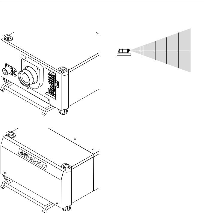
Moving The Projector
Always carry your projector by the handle. Ensure that the power cable and any other cables connecting to video sources are disconnected and the lens is removed from the projector before moving the projector. When moving the projector or when it is not in use, cover the lens with the lens cap.
Selecting A Location
The further your projector is from the screen or wall, the larger the image. The minimum size the image can be projected is 80" (2 m) measured diagonally. The largest the image can be is 500" (12.7 m).
500"
400"
300"
200"
80" 100"
WARNING
•Only use your projector on a solid, level surface. If the projector falls to the ground, you can be injured and the projector severely damaged.
•Do not use the projector where temperatures vary greatly. The projector must be used at temperatures between 40 degrees F (5 degree C) and 95 degrees F (35 degree C).
•Do not expose the projector to moisture, dust, or smoke. This will degrade the screen image.
•Ensure that you have adequate ventilation around your projector for proper heat dissipation. Do not cover the vents on the projector cabinet.
E – 10
 Loading...