


 Loading...
User’s Manual
MultiSync LCD4020
MultiSync LCD4620
MultiSync LCD5220

Index
Declaration of conformity ............................................................................................................................. |
English-1 |
Important Information ................................................................................................................................... |
English-2 |
Warning, Caution ................................................................................................................................ |
English-2 |
Declaration ................................................................................................................................................... |
English-2 |
Safety Precautions, Maintenance & Recommended Use ............................................................................ |
English-3 |
Contents ....................................................................................................................................................... |
English-4 |
Installation .................................................................................................................................................... |
English-5 |
Parts Name and Functions .......................................................................................................................... |
English-8 |
Control Panel ...................................................................................................................................... |
English-8 |
Terminal Panel .................................................................................................................................... |
English-9 |
Wireless Remote Control ................................................................................................................... |
English-10 |
Operating Range for the Remote Control ........................................................................................... |
English-11 |
Handling the remote control ........................................................................................................... |
English-11 |
Setup............................................................................................................................................................. |
English-12 |
Connections ................................................................................................................................................. |
English-14 |
Wiring Diagram ................................................................................................................................... |
English-14 |
Connecting a Personal Computer ...................................................................................................... |
English-15 |
Connect the LCD Monitor to a Personal Computer ........................................................................ |
English-15 |
Connecting to a Macintosh Computer ................................................................................................ |
English-16 |
Connect the LCD Monitor to Macintosh ......................................................................................... |
English-16 |
Connecting with Digital Interface Equipment ...................................................................................... |
English-17 |
Connect the LCD Monitor to a Computer with a Digital Output ...................................................... |
English-17 |
Connecting a DVD Player with component out .................................................................................. |
English-18 |
Connect the LCD Monitor to a DVD Player .................................................................................... |
English-18 |
Connecting a DVD Player with HDMI out ........................................................................................... |
English-19 |
Connect the LCD Monitor to a DVD Player .................................................................................... |
English-19 |
Connecting a DVD Player with SCART out ........................................................................................ |
English-19 |
Connect the LCD Monitor to a DVD Player .................................................................................... |
English-19 |
Connecting to a Stereo Amplifier ........................................................................................................ |
English-20 |
Connect the LCD Monitor to a Stereo Amplifier ............................................................................. |
English-20 |
Basic Operation ........................................................................................................................................... |
English-21 |
Power ON and OFF Modes ................................................................................................................ |
English-21 |
Power Indicator .................................................................................................................................. |
English-22 |
Using Power Management ................................................................................................................. |
English-22 |
Selecting a video source .................................................................................................................... |
English-22 |
Picture Size ........................................................................................................................................ |
English-22 |
Picture Mode ...................................................................................................................................... |
English-22 |
Information OSD ................................................................................................................................. |
English-22 |
OSD (On-Screen-Display) Controls ............................................................................................................. |
English-23 |
PICTURE ............................................................................................................................................ |
English-24 |
ADJUST ............................................................................................................................................. |
English-24 |
AUDIO ................................................................................................................................................ |
English-25 |
SCHEDULE ........................................................................................................................................ |
English-25 |
PIP ...................................................................................................................................................... |
English-26 |
OSD .................................................................................................................................................... |
English-26 |
MULTI DISPLAY ................................................................................................................................. |
English-27 |
DISPLAY PROTECTION .................................................................................................................... |
English-27 |
ADVANCED OPTION ......................................................................................................................... |
English-28 |
Connecting to a TV (For U.S.) ............................................................................................................ |
English-30 |
Connecting to a TV (For Europe) ....................................................................................................... |
English-32 |
Controlling the LCD monitor via RS-232C Remote Control ......................................................................... |
English-36 |
Features ....................................................................................................................................................... |
English-37 |
Troubleshooting ........................................................................................................................................... |
English-38 |
Specifications - LCD4020 ............................................................................................................................ |
English-39 |
Specifications - LCD4620 ............................................................................................................................ |
English-40 |
Specifications - LCD5220 ............................................................................................................................ |
English-41 |
Pin Assignment ............................................................................................................................................ |
English-42 |
Manufacturer’s Recycling and Energy Information ...................................................................................... |
English-43 |
www.necdisplaysolutions.com
DECLARATION OF CONFORMITY
This device complies with Part 15 of FCC Rules. Operation is subject to the following two conditions. (1) This device may not cause harmful interference, and (2) this device must accept any interference received, including interference that may cause undesired operation.
U.S. Responsible Party: NEC Display Solutions of America, Inc.
Address: |
500 Park Boulevard, Suite 1100 |
|
Itasca, Illinois 60143 |
Tel. No.: |
(630) 467-3000 |
Type of Product: |
Computer Monitor |
Equipment Classification: |
Class B Peripheral |
Model: |
MultiSync LCD4020 (L406T6) |
|
MultiSync LCD4620 (L466T7) |
|
MultiSync LCD5220 (L527TE) |
We hereby declare that the equipment specified above conforms to the technical standards as specified in the FCC Rules.
Windows is a registered trademark of Microsoft Corporation. NEC is a registered trademark of NEC Corporation. OmniColor is a registered trademark of NEC Display Solutions Europe GmbH in the countries of EU and Switzerland. All other brands and product names are trademarks or registered trademarks of their respective owners.
Canadian Department of Communications Compliance Statement
DOC: This Class B digital apparatus meets all requirements of the Canadian Interference-Causing Equipment Regulations.
C-UL: Bears the C-UL Mark and is in compliance with Canadian Safety Regulations according to CAN/CSA C22.2 No. 60950-1.
FCC Information
1.Use the attached specified cables with the MultiSync LCD4020 (L406T6)/MultiSync LCD4620 (L466T7)/MultiSync LCD5220 (L527TE) colour monitor so as not to interfere with radio and television reception.
(1)Please use the supplied power cord or equivalent to ensure FCC compliance.
(2)Please use the supplied shielded video signal cable, Mini D-SUB 15 pin to Mini D-SUB 15 pin.
2.This equipment has been tested and found to comply with the limits for a Class B digital device, pursuant to part 15 of the FCC Rules. These limits are designed to provide reasonable protection against harmful interference in a residential installation. This equipment generates, uses, and can radiate radio frequency energy, and, if not installed and used in accordance with the instructions, may cause harmful interference to radio communications. However, there is no guarantee that interference will not occur in a particular installation. If this equipment does cause harmful interference to radio or television reception, which can be determined by turning the equipment off and on, the user is encouraged to try to correct the interference by
one or more of the following measures:
• Reorient or relocate the receiving antenna.
• Increase the separation between the equipment and receiver.
• Connect the equipment into an outlet on a circuit different from that to which the receiver is connected.
• Consult your dealer or an experienced radio/TV technician for help.
If necessary, the user should contact the dealer or an experienced radio/television technician for additional suggestions. The user may find the following booklet, prepared by the Federal Communications Commission, helpful: “How to Identify
and Resolve Radio-TV Interference Problems.” This booklet is available from the U.S. Government Printing Office, Washington, D.C., 20402, Stock No. 004-000-00345-4.
The product you purchased may not have this feature.
LCD4020-BK-AV, LCD4020-2-AV, LCD4020-BK-AVT, LCD4020-2-AVT
LCD4620-BK-AV, LCD4620-2-AV, LCD4620-BK-AVT, LCD4620-2-AVT
LCD5220-BK-AV, LCD5220-BK-AVT only
HDMI, the HDMI logo and High-Definition Multimedia Interface are trademarks or registered trademarks of HDMI Licensing LLC.
English
English-1
Important Information
WARNING
TO PREVENT FIRE OR SHOCK HAZARDS, DO NOT EXPOSE THIS UNIT TO RAIN OR MOISTURE. ALSO, DO NOT USE THIS UNIT’S POLARIZED PLUG WITH AN EXTENSION CORD RECEPTACLE OR OTHER OUTLETS UNLESS THE PRONGS CAN BE FULLY INSERTED.
REFRAIN FROM OPENING THE CABINET AS THERE ARE HIGH VOLTAGE COMPONENTS INSIDE. REFER SERVICING TO QUALIFIED SERVICE PERSONNEL.
CAUTION
CAUTION: TO REDUCE THE RISK OF ELECTRIC SHOCK, MAKE SURE POWER CORD IS UNPLUGGED FROM WALL SOCKET. TO FULLY DISENGAGE THE POWER TO THE UNIT, PLEASE DISCONNECT THE POWER CORD FROM THE AC OUTLET. DO NOT REMOVE COVER (OR BACK). NO USER SERVICEABLE PARTS INSIDE. REFER SERVICING TO QUALIFIED SERVICE PERSONNEL.
This symbol warns user that uninsulated voltage within the unit may have sufficient magnitude to cause electric shock. Therefore, it is dangerous to make any kind of contact with any part inside this unit.
This symbol alerts the user that important literature concerning the operation and maintenance of this unit has been included. Therefore, it should be read carefully in order to avoid any problems.
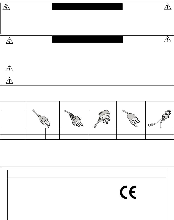
CAUTION: Please use the power cord provided with this display in accordance with the table below. If a power cord is not supplied with this equipment, please contact your supplier. For all other cases, please use a power cord that matches the AC voltage of the power outlet and has been approved by and complies with the safety standard of your particular country.
Plug Type |
North America |
European |
U.K. |
Chinese |
Japanese |
||
Continental |
|||||||
|
|
|
|
|
|
||
Plug Shape |
|
|
|
|
|
|
|
Region |
U.S.A./Canada |
Taiwan |
EU (except U.K.) |
U.K. |
China |
Japan |
|
Voltage |
120* |
110* |
230 |
230 |
220 |
100 |
|
*When operating the MultiSync LCD4020/MultiSync LCD4620/MultiSync LCD5220 monitor with its AC 125-240V power supply, use a power supply cord that matches the power supply voltage of the AC power outlet being used.
NOTE: This product can only be serviced in the country where it was purchased.
Declaration
Declaration of the Manufacturer
We hereby certify that the color monitor MultiSync LCD4020 (L406T6)/MultiSync LCD4620 (L466T7)/ MultiSync LCD5220 (L527TE) are in compliance with
Council Directive 2006/95/EC:
– EN 60950-1
Council Directive 2004/108/EC:
–EN 55022
–EN 61000-3-2
–EN 61000-3-3
–EN 55024
and marked with
NEC Display Solutions, Ltd.
4-13-23, Shibaura,
Minato-Ku
Tokyo 108-0023, Japan
English-2

Safety Precautions, Maintenance & Recommended Use
FOR OPTIMUM PERFORMANCE, PLEASE NOTE THE FOLLOWING WHEN SETTING UP AND USING
THE MULTI-FUNCTION MONITOR:
•DO NOT OPEN THE MONITOR. There are no user serviceable parts inside and opening or removing covers may expose you to dangerous shock hazards or other risks. Refer all servicing to qualified service personnel.
•Do not spill any liquids into the cabinet or use your monitor near water.
•Do not insert objects of any kind into the cabinet slots, as they may touch dangerous voltage points, which can be harmful or fatal or may cause electric shock, fire or equipment failure.
•Do not place any heavy objects on the power cord. Damage to the cord may cause shock or fire.
•Do not place this product on a sloping or unstable cart, stand or table, as the monitor may fall, causing serious damage to the monitor.
•The power supply cord you use must have been approved by and comply with the safety standards of your country. (Type H05VV-F 3G 1mm2 should be used in Europe)
•In UK, use a BS-approved power cord with molded plug having a black (13A) fuse installed for use with this monitor.
•Do not place any objects onto the monitor and do not use the monitor outdoors.
•The lamps in this product contain mercury. Please
dispose according to state, local or federal law.
•Do not bend, crimp or otherwise damage the power cord.
•If glass is broken, handle with care.
•Do not cover vent on monitor.
•Do not use monitor in high temperature, humid, dusty, or oily areas.
•If monitor or glass is broken, do not come in contact with the liquid crystal and handle with care.
•Allow adequate ventilation around the monitor, so that heat can properly dissipate. Do not block ventilated openings or place the monitor near a radiator or other heat sources.
Do not put anything on top of the monitor.
•The power cable connector is the primary means of detaching the system from the power supply. The monitor should be installed close to a power outlet, which is easily accessible.
•Handle with care when transporting. Save packaging for transporting.
•Please clean the holes of back cabinet to reject dirt and dust at least once a year because of set reliability.
•If using the cooling fan continuously, it’s recommended to wipe holes a minimum of once a month.
Immediately unplug your monitor from the wall outlet and refer servicing to qualified service personnel under the following conditions:
•When the power supply cord or plug is damaged.
•If liquid has been spilled, or objects have fallen into the monitor.
•If the monitor has been exposed to rain or water.
•If the monitor has been dropped or the cabinet damaged.
•If the monitor does not operate normally by following operating instructions.
Recommended Use
•For optimum performance, allow 20 minutes for warm-up.
•Rest your eyes periodically by focusing on an object at least 5 feet away. Blink often.
•Position the monitor at a 90° angle to windows and other light sources to minimize glare and reflections.
•Clean the LCD monitor surface with a lint-free, non-abrasive cloth. Avoid using any cleaning solution or glass cleaner!
•Adjust the monitor’s brightness, contrast and sharpness controls to enhance readability.
•Avoid displaying fixed patterns on the monitor for long periods of time to avoid image persistence (after image effects).
•Get regular eye checkups.
Ergonomics
To realize the maximum ergonomic benefits, we recommend the following:
•Use the preset Size and Position controls with standard signals.
•Use the preset Color Setting.
•Use non-interlaced signals.
•Do not use primary color blue on a dark background, as it is difficult to see and may produce eye fatigue due to insufficient contrast.
Cleaning the LCD Panel
•When the liquid crystal panel is stained with dust or dirt, please wipe with soft cloth gently.
•Please do not rub the LCD panel with hard material.
•Please do not apply pressure to the LCD surface.
•Please do not use OA cleaner it will cause deterioration or discolor on the LCD surface.
Cleaning the Cabinet
•Unplug the power supply
•Gently wipe the cabinet with a soft cloth
•To clean the cabinet, dampen the cloth with a neutral detergent and water, wipe the cabinet and follow with a dry cloth.
NOTE: The surface of the cabinet is composed of many types of plastic. DO NOT clean with benzene thinner, alkaline detergent, alcoholic system detergent, glass cleaner, wax, polish cleaner, soap powder, or insecticide. Rubber or vinyl should not be in contact with the cabinet for an extended period of time. These types of fluids and materials can cause the paint to deteriorate, crack or peel.
English
English-3
Contents
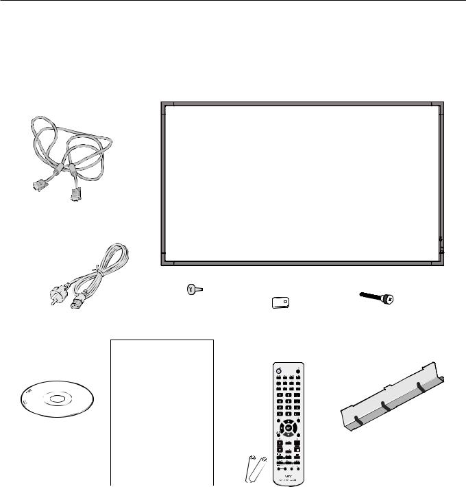
Your new MultiSync monitor box* should contain the following: |
|
|
|
• |
LCD monitor |
• |
Cable Cover |
• |
Power Cord*1 |
• |
Clamp x 3 |
• |
Video Signal Cable |
• Screw (M4 x 10) x 9 |
|
• |
User’s Manual |
• |
CD-ROM |
• Wireless Remote Control and AA Batteries |
• Thumbscrew for stand x 2 |
||
Video Signal Cable (Mini D-SUB 15 pin to Mini D-SUB 15 pin)
|
|
|
|
|
Screw (M4 x 10) x 9 |
||
Power Cord*1 |
|
|
Thumbscrew for stand x 2 |
|
|
|
Clamp x 3 |
User’s Manual
CD-ROM
Cable cover
|
|
|
|
|
|
User’s Manual |
Wireless Remote Control |
||||
|
and AA Batteries |
||||
*1 Type and number of power cords included will depend on the where the LCD monitor is to be shipped. When more than one power cord is included, please use a power cord that matches the AC voltage of the power outlet and has been approved by and complies with the safety standard of your particular country.
*Depending on where the LCD is sold, the stand may or may not be included with some models.
*Remember to save your original box and packing material to transport or ship the monitor.
English-4
Installation
This device cannot be used or installed without the Tabletop Stand or other mounting accessory for support. For proper installation it is strongly recommended to use a trained, NEC authorized service person. Failure to follow NEC standard mounting procedures could result in damage to the equipment or injury to the user or installer. Product warranty does not cover damage caused by improper installation. Failure to follow these recommendations could result in voiding the warranty.
Mounting
DO NOT mount the monitor yourself. Please ask dealer. For proper installation it is strongly recommended to use a trained, qualified technician. Please inspect the location where the unit is to be mounted. Mounting on wall or ceiling is the customer’s responsibility. Not all walls or ceilings are capable of supporting the weight of the unit. Product warranty does not cover damage caused by improper installation, remodelling, or natural disasters. Failure to comply with these recommendations could result in voiding the warranty.
DO NOT block ventilated openings with mounting accessories or other accessories.
For NEC Qualified Personnel:
To insure safe installation, use two or more brackets to mount the unit. Mount the unit to at least two points on the installation location.
Please note the following when mounting on wall or ceiling
•When using mounting accessories other than those that are NEC approved, they must comply with the VESAcompatible (FDMlv1) mounting method.
• NEC strongly recommends |
Unit |
|
using size M6 screws |
||
|
||
(10 mm (LCD4020/ |
|
|
LCD4620) or 12 mm |
|
|
(LCD5220) + thickness of |
|
|
bracket in length). If using |
|
|
screws longer than 10 mm |
|
|
(LCD4020/LCD4620) or |
|
|
12 mm (LCD5220), check |
|
|
the depth of the hole. |
|
(Recommended Fasten Force: 470 - 635N•cm) NEC recommends mounting interfaces that comply with
UL1678 standard in North America.
|
|
|
|
|
Mounting |
|
|
|
|
|
Bracket |
10 mm |
|
|
|
|
Screw |
|
|
|
|
||
|
|
|
|
Thickness |
|
|
|
|
|
||
|
|
|
|
||
or |
|
|
|
|
|
|
|
|
|
||
12 mm |
|
|
|
|
of Bracket |
|
|
|
|
|
•Prior to mounting, inspect the installation location to insure that it is strong enough to support the weight of the unit so that the unit will be safe from harm.
•Refer to the instructions included with the mounting equipment for detailed information.
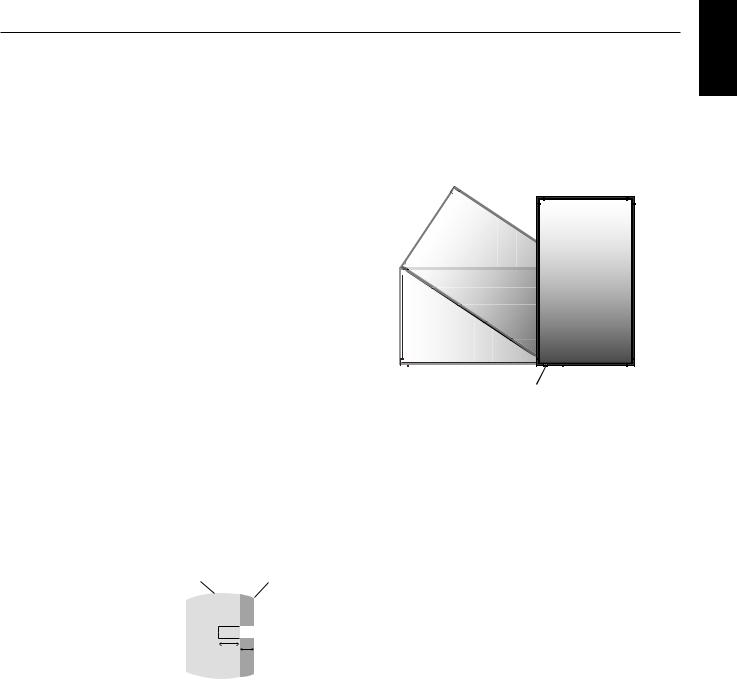
Orientation
•When using the display in the portrait position, the monitor should be rotated clockwise so that the left side is moved to the top and the LCD indicator light is on the bottom. This will allow for proper ventilation and will extend the lifetime of the monitor. Improper ventilation may shorten the lifetime of the monitor.
LED Indicator
Mounting location
•The ceiling and wall must be strong enough to support the monitor and mounting accessories.
•DO NOT install in locations where a door or gate can hit the unit.
•DO NOT install in areas where the unit will be subjected to strong vibrations and dust.
•DO NOT install near where the main power supply enters the building.
•Do not install in where people can easily grab and hang onto the unit or the mounting apparatus.
•When mounting in a recessed area, as in a wall, leave at least 4 inches (10cm) of space between the monitor and the wall for proper ventilation.
•Allow adequate ventilation or provide air conditioning around the monitor, so that heat can properly dissipate away from the unit and mounting apparatus.
Mounting on ceiling
•Ensure that the ceiling is sturdy enough to support the weight of the unit and the mounting apparatus over time, against earthquakes, unexpected vibrations, and other external forces.
•Be sure the unit is mounted to a solid structure within the ceiling, such as a support beam. Secure the monitor using bolts, spring lock washers, washer and nut.
•DO NOT mount to areas that have no supporting internal structure. DO NOT use wood screws or anchor screws for mounting. DO NOT mount the unit to trim or to hanging fixtures.
Maintenance
•Periodically check for loose screws, gaps, distortions, or other problems that may occur with the mounting apparatus. If a problem is detected, please refer to qualified personnel for service.
•Regularly check the mounting location for signs of damage or weakness that may occur over time.
English-5
English
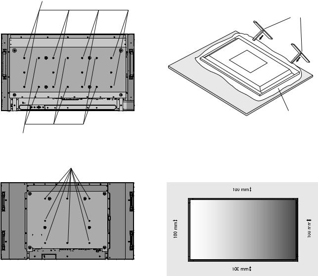
Attaching Mounting Accessories
The display is designed for use with the VESA mounting system.
1. Attach Mounting Accessories
Be careful to avoid tipping monitor when attaching accessories.
LCD4020/LCD4620
Using 8 holes
Using 6 holes
LCD5220
VESA Mounting Interface
Figure 1
Mounting accessories can be attached with the monitor in the face down position. To avoid damaging the screen face, place the protective sheet on the table underneath the LCD. The protective sheet was wrapped around the LCD in the original packaging. Make sure there is nothing on the table that can damage the monitor.
When using mounting accessories other than NEC compliant and approved, they must comply with the VESAcompatible mounting method.
2.Installing and removing optional table top stand
CAUTION: Installing and removing the stand must be done by four or more people (LCD5220), by two or more people (LCD4020/LCD4620).
To install, follow those instructions included with the stand or mounting apparatus. Use only those devices recommended by the manufacturer.
Handle with care when mounting LCD monitor stand and avoid pinching your fingers.
Optional table top stand
Table
Protective Sheet
NOTE: Place stand onto monitor so that the long end of the feet are in the front.
3. Ventilation Requirements
When mounting in an enclosed space or recessed area, leave adequate room between the monitor and the enclosure to allow heat to disperse, as shown below.
English-6
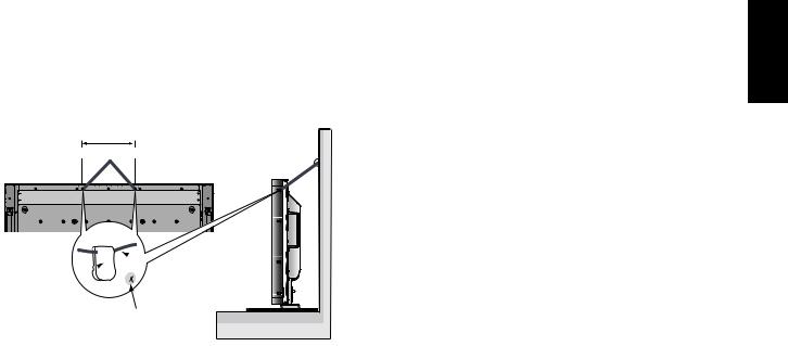
4. Prevent Tipping
When using the display with the Tabletop Stand fasten the LCD to a wall using a cord or chain that can support the weight of the monitor in order to prevent the monitor from falling. Fasten the cord or chain to the monitor using the provided clamp and screw.
LCD4020: 278 mm
LCD4620: 210 mm
LCD5220: 400 mm
Screw Holes


 Cord or chain
Clamp
Screw
Before attaching the LCD monitor to the wall, make sure that the wall can support the weight of the monitor.
Be sure to remove the cord or chain from the wall before moving the LCD.
English
English-7
Parts Name and Functions
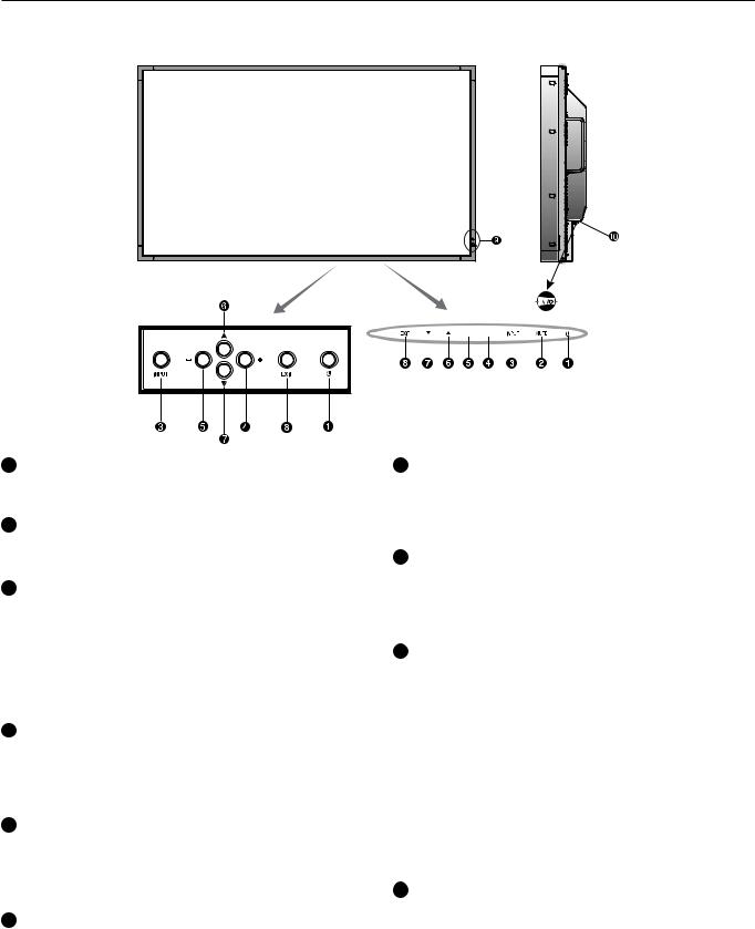
Control Panel
|
ON |
OFF |
LCD4020/LCD4620 |
LCD5220 |
|
1 POWER button ( )
)
Switches the power on/off. See also page 21.
2 MUTE button (LCD5220 only)
Switches the audio mute ON/OFF.
3 INPUT button
Acts as SET button within OSD menu. (Toggle switches between [DVI], [VGA], [RGB/HV], [HDMI]*, [DVD/HD]*, [VIDEO]*, [S-VIDEO]* or [TV]*). [S-VIDEO] is enabled by selecting the “SEPARATE” mode in the OSD or by having the “S-VIDEO” cable connected with the “S-VIDEO” signal present and selecting “PRIORITY” MODE. See page 28.
4 PLUS (+) button
Acts as (+) button to increase the adjustment with OSD menu. Increases the audio output level when the OSD menu is turned off*.
5 MINUS (-) button
Acts as (-) button to decrease the adjustment with OSD menu. Decreases the audio output level when the OSD menu is turned off*.
6 UP ( ) button
Activates the OSD menu when the OSD menu is turned-off. Acts as  button to move the highlighted area up to select adjustment items within OSD menu.
7 DOWN ( ) button
Activates the OSD menu when the OSD menu is turned-off. Acts as  button to move the highlighted area down to select adjustment items within OSD menu.
8 EXIT button
Activates the OSD menu when the OSD menu is turned-off. Acts as EXIT button within the OSD to move to previous menu.
9 Remote control sensor and Power Indicator
Receives the signal from the remote control (when using the wireless remote control). See also page 11.
Glows green when the LCD monitor is in active mode*. Glows red when the LCD is in POWER OFF (ECO standby) mode. Glows amber when the LCD is in POWER OFF (standby) mode. Blinks amber when the monitor is in Power Save Mode. Green and Amber blink alternately while in Power Standby mode with the “SCHEDULE SETTINGS” function enabled. When a component failure is detected within the monitor, the indicator will blink red.
* If “OFF” is selected in “POWER INDICATOR” (see page 22), LED will not light when the LCD monitor is in active mode.
10 Main Power Switch
On/Off switch to turn main power ON/OFF.
Control Key Lock Mode
This control completely locks out access to all Control Key functions. To activate the control key lock function, press both  and
and  and hold down simultaneously for more than
3 seconds. To resume user mode, press both  and
and  and hold simultaneously for more than 3 seconds.
*: The product you purchased may not have this feature.
English-8

Terminal Panel
English
LCD4020/LCD4620 |
LCD5220 |
Out |
In |
1 AC IN connector
Connects with the supplied power cord.
2 DVI IN (DVI-D)
9 AUDIO OUT*
To output the audio signal from the AUDIO IN 1, 2, 3, HDMI, and TV jack to an external device (stereo receiver, amplifier, etc.).
To input digital RGB signals from a computer or HDTV device having a digital RGB output.
* This connector does not support analog input.
3 VGA IN (mini D-Sub 15 pin)
To input analog RGB signals from a personal computer or from other RGB equipment.
4 RGB/HV IN [R, G, B, H, V] (BNC)
To input analog RGB signals or signals from other RGB equipment.
This is also to connect equipment such as a DVD player, HDTV device and Set-Top-Box. A Sync-on-Green signal can be connected to the G connector.
5 RGB/HV OUT (BNC)
To outputs the signal from the RGB/HV IN connector to an input on a separate device.
6 HDMI connector*
To input digital HDMI signals.
7 DVD/HD connector* (RCA)
Connecting equipment such as a DVD player, HDTV device, or Set-Top-Box.
8 AUDIO IN* 1, 2, 3
To input audio signal from external equipment such as a computer, VCR or DVD player.
10 VIDEO INPUT/OUTPUT Connector*
VIDEO IN connector (BNC and RCA): To input a composite video signal. BNC and RCA connectors are not available at the same time (Use only one input).
VIDEO OUT connector (BNC): To output the composite video signal from the VIDEO IN connector.
S-VIDEO IN connector (Mini DIN 4 pin): To input the S-video (Y/C separate signal). See page 28, S-VIDEO MODE SETTING.
11 EXTERNAL CONTROL (D-Sub 9 pin)
IN connector: Connect RS-232C input from external equipment such as a PC in order to control RS-232C functions.
Out connector: Connect RS-232C output. To connect multiple MultiSync monitors via RS-232C daisy Chain.
12 EXTERNAL SPEAKER TERMINAL*
To output the audio signal from AUDIO 1, 2, 3, HDMI and TV jack.
Note: This speaker terminal is for 15W + 15W (8 ohm) speaker.
13 RF IN* (For U.S.)
TV signal input.
14 S/PDIF OUTPUT* (For U.S.)
Optical digital audio out.
15 Antenna Input* (For Europe)
Connects to antenna or to TV signal.
*: The product you purchased may not have this feature.
English-9
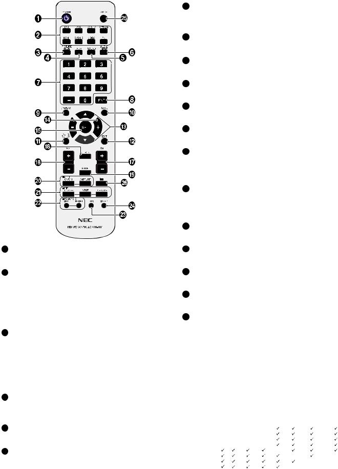
Wireless Remote Control
1 POWER button
Switches the power on/off.
2 INPUT button
Selects input signal, [DVI], [VGA], [RGB/HV], [HDMI]*, [DVD/HD]*, [VIDEO]*, [TV]* or [S-VIDEO]*.
[S-VIDEO] is enabled by selecting the “SEPARATE” mode in the OSD or by having the “S-VIDEO” cable connected with an “S-VIDEO” signal present and selecting “PRIORITY” MODE in the S-VIDEO OSD menu. See page 28.
3 PICTURE MODE button
Selects picture mode, [HIGHBRIGHT], [STANDARD], [sRGB], [CINEMA]*. See page 22.
HIGHBRIGHT: for moving images such as DVD STANDARD: for images
sRGB: for text based images CINEMA: for movies.
4 SIZE button
Selects picture size, [FULL], [NORMAL], [WIDE]* and [ZOOM]. See page 22.
5 SOUND button*
Artificial surround sound.
6 AUDIO INPUT button*
Selects audio input source [IN1], [IN2], [IN3], [HDMI], [TV]*.
7 KEYPAD
Press buttons to set and change passwords, change channel and set REMOTE ID.
8 ENT button*
Sets channels.
9 DISPLAY button
Turns on/off the information OSD. See page 22.
10 MENU button
Turns on/off the menu mode.
11 AUTO SETUP button
Enters auto setup menu. See page 24.
12 EXIT button
Returns to previous menu within OSD menu.
13 UP/DOWN button
Acts as button to move the highlighted area up or down to select adjustment items within OSD menu.
Small screen which adjusted “PIP” mode moves up or down.
14 MINUS/PLUS (+/-) button
Increases or decreases the adjustment level within OSD menu settings.
Small screen which adjusted “PIP” mode moves left or right.
15 SET button
Makes selection.
16 VOLUME UP/DOWN button*
Increases or decreases audio output level.
17 CH +/- button*
Moves channel up or down.
18 CH RTN button*
Returns to previous channel.
19 MUTE button
Turns on/off mute function.
 STILL button
ON/OFF button: Activates/deactivates still picture mode. STILL CAPTURE button: Captures still picture.
 PIP (Picture In Picture) button
ON/OFF button: Toggle switches between PIP, POP, side- by-side (aspect) and side-by-side (full). See page 26. INPUT button: Selects the “picture in picture” input signal. CHANGE button: Replaces to the main picture and sub picture.
|
|
|
|
|
|
Sub picture |
|
|
|
|
|
DVI |
VGA |
RGB/HV |
HDMI |
DVD/HD |
VIDEO |
TV for U.S. |
TV for Europe |
|
DVI |
- |
- |
- |
- |
|
|
|
|
picture |
VGA |
- |
- |
- |
- |
|
|
|
|
RGB/HV |
- |
- |
- |
- |
|
|
|
|
|
|
HDMI |
- |
- |
- |
- |
|
|
|
|
Main |
DVD/HD |
|
|
|
|
- |
|
|
|
VIDEO |
|
|
|
|
|
- |
|
- |
|
|
TV for U.S. |
|
|
|
|
|
|
- |
- |
|
TV for Europe |
|
|
|
|
|
- |
- |
- |
*: The product you purchased may not have this feature.
English-10
 REMOTE ID button
Activates REMOTE ID function.
 MTS button*
Multichannel television sound.
 SLEEP button
Sets power off timer.
 GUIDE button*
Enters on screen program guide (For U.S.).


 button*
Activates closed captioning (For U.S.). Activates Teletext (For Europe).
*: The product you purchased may not have this feature.
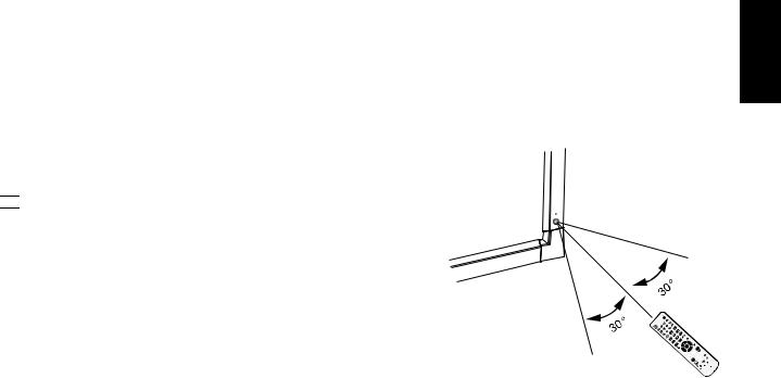
Operating Range for the Remote
remote sensor during button operation. |
English |
Control |
|
Point the top of the remote control toward the LCD monitor’s |
|
Use the remote control within a distance of about 7 m (23 ft.) |
|
from the front of the LCD monitor’s remote control sensor or |
|
at a horizontal and vertical angle of within 30° within a |
|
distance of about 3.5 m (10 ft.) |
|
Caution: Important, the remote
control system may not function when
direct sunlight or strong 


 illumination strikes the remote control
 sensor of the LCD monitor, or when there is
an object in the path.
Handling the remote control
•Do not subject to strong shock.
•Do not allow water or other liquid to splash the remote control. If the remote control gets wet, wipe it dry immediately.
•Avoid exposure to heat and steam.
•Other than to install the batteries, do not open the remote control.
English-11
Setup
1. Determine the installation location
CAUTION: Installing your LCD display must be done by a qualified technician. Contact your dealer for more information.
CAUTION: MOVING OR INSTALLING THE LCD MONITOR MUST BE DONE BY FOUR OR MORE PEOPLE (LCD5220), BY TWO OR MORE PEOPLE (LCD4020/LCD4620). Failure to follow this caution may result in injury if the LCD monitor falls.
NOTE: If you do not intend to use the Remote Control for a long period of time, remove the batteries.
3. Connect external equipment (See pages 14-20)
•To protect the external equipment; turn off the main power before making connections.
•Refer to your equipment user manual for further information.
CAUTION: Do not mount or operate the display upside down, face up, or face down.
CAUTION: This LCD has a temperature sensor and cooling fan. If the LCD becomes too hot, the cooling fan will turn on automatically. If the LCD becomes overheated while the cooling fan is running, a “Caution” warning will appear. If the “Caution” warning appears, discontinue use and allow the unit to cool. Using the cooling fan will reduce the likelihood of early circuit failure and may help reduce image degradation and “Image Persistance”.
If the LCD is used in an enclosed area or if the LCD panel is covered with a protective screen, please check the inside temperature of the monitor by using the “HEAT STATUS” control in the OSD (see page 27). If the temperature is higher than the normal operating temperature, please turn the cooling fan to ON within the FAN CONTROL menu within the OSD (see page 27).
IMPORTANT: Lay the protective sheet, which was wrapped around the LCD monitor when it was packaged, beneath the LCD monitor so as not to scratch the panel.
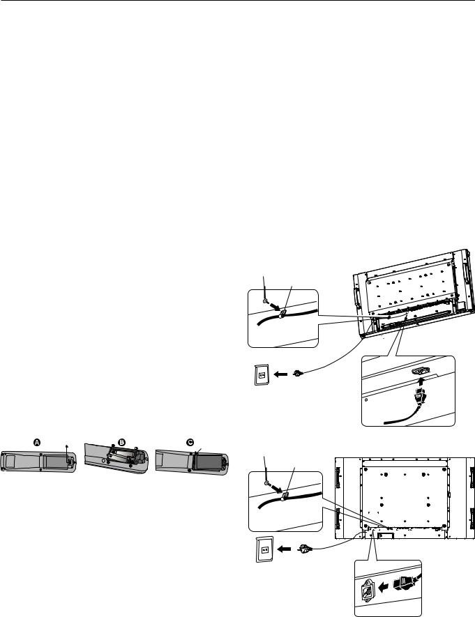
2. Install the remote control batteries
The remote control is powered by two 1.5V AA batteries. To install or replace batteries:
A.Press and slide to open the cover.
B.Align the batteries according to the (+) and (–) indications inside the case.
C.Replace the cover.
CAUTION: Incorrect usage of batteries can result in leaks or bursting.
NEC recommends the following battery use:
•Place “AA” size batteries matching the (+) and (-) signs on each battery to the (+) and (-) signs of the battery compartment.
•Do not mix battery brands.
•Do not combine new and old batteries. This can shorten battery life or cause liquid leakage of batteries.
•Remove dead batteries immediately to prevent battery acid from leaking into the battery compartment.
•Do not touch exposed battery acid, it may injure skin.
4. Connect the supplied power cord
•The equipment should be installed close to an easily accessible power outlet.
•Please fasten power cord to the LCD monitor by attaching the screw and clamp.
•Fully insert the prongs into the power outlet socket. A loose connection may cause image degradation.
NOTE: Please refer to the “Safety Precautions and Maintenance” section of this manual for proper selection of AC power cord.
LCD4020/4620
Screw
Clamp
Screw hole for clamp 
LCD5220
Screw
Clamp
English-12
Loading...