


 LCD Projector


 GT1150


 User’s Manual


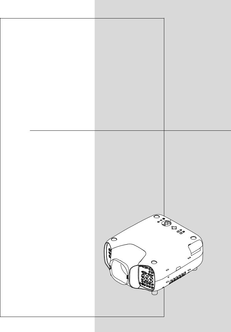
LCD Projector
GT1150
User’s Manual
ECRUOS
|
YB |
DNATS/ |
|
R E |
WOP |
|
|
|
NO |
|
|
||
|
|
|
|
SUT |
|
|
TS |
UJD A |
|
|
|
ATS |
|
OTUA |
|
|
|
|
PMAL |
|
|
|
|
|
|
|
NAC |
R
SELECT
UNEM
RIGHT |
|
N |
DOW |
|
|
SHIFT |
LENS |
|
|
|
|
|
|
|
UP |
|
|
LEFT |
ZOOM |
FOCUS
DECLARATION OF CONFORMITY
This device complies with Part 15 of FCC Rules. Operation is subject to the following two conditions. (1) This device may not cause harmful interference, and (2) this device must accept any interference received, including interference that may cause undesired operation.
U.S. Responsible Party: |
NEC Technologies, Inc. |
Address: |
1250 N. Arlington Heights Road |
|
Itasca, Illinois 60143 |
Tel. No.: |
(630) 467-5000 |
|
|
Type of Product: |
LCD Projector |
Equipment Classification: |
Class B Peripheral |
Models: |
GT1150 |
We hereby declare that the equipment specified above conforms to the technical standards as specified in the FCC Rules.
IMPORTANT INFORMATION
Precautions
Please read this manual carefully before using your NEC GT1150 Projector and keep the manual handy for future reference.
Your serial number is located on the bottom of your GT1150. Record it here:
CAUTION
To turn off main power, be sure to remove the plug from power outlet.
The power outlet socket should be installed as near to the equipment as possible, and should be easily accessible.
CAUTION
TO PREVENT SHOCK, DO NOT OPEN THE CABINET. NO USER-SERVICEABLE PARTS INSIDE.
REFER SERVICING TO QUALIFIED NEC SERVICE PERSONNEL.
This symbol warns the user that uninsulated voltage within the unit may be sufficient to cause electrical shock.
Therefore, it is dangerous to make any kind of contact with any part inside of the unit.
This symbol alerts the user that important information concerning the operation and maintenance of this unit has been provided.The information should be read carefully to avoid problems.
RF Interference
WARNING
The Federal Communications Commission does not allow any modifications or changes to the unit EXCEPT those specified by
NEC Technologies in this manual. Failure to comply with this government regulation could void your right to operate this equipment.
This equipment has been tested and found to comply with the limits for a Class B digital device, pursuant to Part 15 of the FCC
Rules.These limits are designed to provide reasonable protection against harmful interference in a residential installation.This equipment generates, uses, and can radiate radio frequency energy and, if not installed and used in accordance with the instructions, may cause harmful interference to radio communications. However, there is no guarantee that interference will not occur in a particular installation. If this equipment does cause harmful interference to radio or television reception, which can be determined by turning the equipment off and on, the user is encouraged to try to correct the interference by one or more of the following measures:
•Reorient or relocate the receiving antenna.
•Increase the separation between the equipment and receiver.
•Connect the equipment into an outlet on a circuit different from that to which the receiver is connected.
•Consult the dealer or an experienced radio / TV technician for help.
In UK, a BS approved power cable with moulded plug has a Black (five Amps) fuse installed for use with this equipment. If a power cable is not supplied with this equipment please contact your supplier.
WARNING
TO PREVENT FIRE OR SHOCK, DO NOT EXPOSE THIS UNIT TO
RAIN OR MOISTURE.
DO NOT USE THIS UNIT’S GROUNDED PLUG WITH AN EXTEN-
SION CORD OR IN AN OUTLET UNLESS ALL THREE PRONGS CAN
BE FULLY INSERTED.
DO NOT OPEN THE CABINET. THERE ARE HIGH-VOLTAGE COM-
PONENTS INSIDE. ALL SERVICING MUST BE DONE BY QUALI-
FIED NEC SERVICE PERSONNEL.
DOC Compliance Notice
This Class B digital apparatus meets all requirements of the Canadian
Interference-Causing Equipment Regulations.
3. GSGV Acoustic Noise Information Ordinance:
The sound pressure level is less than 70 dB (A) according to ISO 3744 or ISO 7779.
• IBM is a registered trademark of International Business Machines
Corporation.
• Macintosh and PowerBook are registered trademarks of Apple Computer, Inc.
• Other product and company names mentioned in this user's manual may be the trademarks of their respective holders.
E – ii
INFORMATIONS IMPORTANTES
Précautions
Veuillez lire ce manuel avec attention avant d’utiliser votre projecteur
NEC GT1150 et gardez ce manuel à portée de main afin de pouvoir y recourir facilement.
Votre numéro de série est situé sur le fond de votre GT1150. Reportezle ici:
ATTENTION
Pour couper complètement l’alimentation, retirez la prise du secteur.
La prise du secteur doit être accessible et installée le plus près possible de l’appareil.
ATTENTION
POUR ÉVITER TOUT CHOC ÉLECTRIQUE, N’OUVREZ PAS LE
BOÎTIER. LES PIÈCES INTERNES NE SONT PAS RÉPARABLES
PAR L’UTILISATEUR. POUR TOUTE RÉPARATION, ADRESSEZ-
VOUS À UN RÉPARATEUR AGRÉE NEC.
Ce symbole avertit l’utilisateur que le contact avec certaines parties non isolées à l’intérieur de l’appareil risque de causer une électrocution. Il est donc dangereux de toucher quoi que ce soit à l’intérieur de l’appareil.
Ce symbole avertit l’utilisateur que d’importantes informations sont fournies sur le fonctionnement ou l’entretien de cet appareil. Ces informations doivent être lues attentivement pour éviter tout problème.
AVERTISSEMENT
AFIN DE PREVENIR TOUT RISQUE D’INCENDIE OU DE CHOC
ÉLECTRIQUE, N’EXPOSEZ PAS CET APPAREIL À LA PLUIE OU À
L’HUMIDITÉ. N’UTILISEZ PAS LA PRISE AVEC TERRE DE L’APPAREIL AVEC UNE RALLONGE OU UNE AUTRE PRISE, A
MOINS QUE LES TROIS BROCHES PUISSENT ÊTRE
COMPLETEMENT INSÉRÉES. N’OUVREZ PAS LE BOÎTIER. A L’INTÉRIEUR SE TROUVENT DES COMPOSANTS À HAUTE TEN-
SION. TOUTE RÉPARATION DOIT ÊTRE FAITE PAR DU PERSON-
NEL AGRÉE NEC.
DOC avis de conformation
Cet appareil numérique de la classe B respecte toutes les exigences du Règlement sur le Matériel Brouilleur du Canada.
3. Réglement sur les informations concernant les nuisances acoustiques GSGV:
Le niveau de pression sonore est inférieur à 70 dB (A) conformément à la norme ISO 3744 ou ISO 7779.
• IBM est une marque déposées de International Business Machines
Corporation.
• Macintosh et PowerBook sont des marques déposées de Apple Computer, Inc.
• Tous les autres marques et les noms de produits sont des marques de fabrique ou des marques déposées de leurs compagnies respectives.
E – iii

Important Safeguards
These safety instructions are to ensure the long life of your projector and to prevent fire and shock. Please read them carefully and heed all warnings.
Installation
1.For best results, use your projector in a darkened room.
2.Place the projector on a flat, level surface in a dry area away from dust and moisture.
3.Do not place your projector in direct sunlight, near heaters or heat radiating appliances.
4.Exposure to direct sunlight, smoke or steam can harm internal components.
5.Handle your projector carefully. Dropping or jarring can damage internal components.
6.Do not place heavy objects on top of the projector.
7.If you wish to have the projector installed on the ceiling:
a.Do not attempt to install the projector yourself.
b.The projector must be installed by qualified technicians in order to ensure proper operation and reduce the risk of bodily injury.
c.In addition, the ceiling must be strong enough to support the projector and the installation must be in accordance with any local building codes.
d.Please consult your dealer for more information.
Power Supply
1.The projector is designed to operate on a power supply of 100-120 or 200-240 V 50/60 Hz AC. Ensure that your power supply fits this requirement before attempting to use your projector.
2.Handle the power cable carefully and avoid excessive bending. A damaged cord can cause electric shock or fire.
3.If the projector is not to be used for an extended period of time, disconnect the plug from the power outlet.
Cleaning
1.Unplug the projector before cleaning.
2.Clean the cabinet periodically with a damp cloth. If heavily soiled, use a mild detergent. Never use strong detergents or solvents such as alcohol or thinner.
3.Use a blower or lens paper to clean the lens, and be careful not to scratch or mar the lens.
CAUTION
Do not unplug the power cable from the wall outlet under any one of the following circumstances. Doing so can cause damage to the projector:
•While the Hour Glass icon appears.
•While the message "Please wait a moment." appears. This message will be displayed after the projector is turned off.
•Immediately after the power cable is plugged into the wall outlet (the POWER indicator has not changed to a steady orange glow).
•Immediately after the cooling fan stops working (The cooling fan continues to work for ONE minute after the projector is turned off with the POWER button).
•While the POWER and the STATUS indicators are alternately flashing.
CAUTION
•Do not put the projector on its side when the lamp is turned on. Doing so may cause damage to the projector.
•Before shipping this projector, remove the lens and attach the lens hood cap.
The Lens Shift mechanism may encounter damage caused by improper handling during transportation.
Lamp Replacement
•To replace the lamp, follow all instructions provided on page E-58.
•Be sure to replace the lamp when the message "The Lamp has reached the end of its usable life. Please replace the lamp." appears. If you continue to use the lamp after the lamp has reached the end of its usable life, the lamp bulb may shatter, and pieces of glass may be scattered in the lamp case. Do not touch them as the pieces of glass may cause injury. If this happens, contact your NEC dealer for lamp replacement.
•Allow a minimum of ONE minute to elapse after turning off the projector. Then disconnect the power cable and allow 60 minutes to cool the projector before replacing the lamp.
Fire and Shock Precautions
1.Ensure that there is sufficient ventilation and that vents are unobstructed to prevent the build-up of heat inside your projector. Allow at least 3 inches (10 cm) of space between your projector and a wall.
2.Prevent foreign objects such as paper clips and bits of paper from falling into your projector. Do not attempt to retrieve any objects that might fall into your projector. Do not insert any metal objects such as a wire or screwdriver into your projector. If something should fall into your projector, disconnect it immediately and have the object removed by a qualified NEC service personnel.
3.Do not place any liquids on top of your projector.
•Do not look into the lens while the projector is on. Serious damage to your eyes could result.
•Keep any items such as magnifying glass out of the light path of the projector. The light being projected from the lens is extensive, therefore any kind of abnormal objects that can redirect light coming out of the lens, can cause unpredictable outcome such as fire or injury to the eyes.
•Do not cover the lens with the supplied lens cap or equivalent while the projector is on. Doing so can lead to melting of the cap and possibly burning your hands due to the heat emitted from the light output.
4.When using a LAN cable:
For safety, do not connect to the connector for peripheral device wiring that might have excessive Voltage.
E – iv

Mesures de sécurité importantes
Ces instructions de sécurité garantissent la longévité de votre projecteur et préviennent les risques d’incendie et de décharge électrique. Lisezles et respectez les conseils.
Installation
1.Pour de meilleurs résultats‚ utilisez votre projecteur dans une pièce sombre.
2.Placez le projecteur sur une surface plane et à niveau, dans un endroit sec à l’abri de la poussière et de l’humidité.
3.Ne placez pas votre projecteur en plein soleil‚ à côté d’appareils de chauffage ou d’appareils dégageant de la chaleur.
4.L’exposition en plein soleil‚ la fumée ou la vapeur peuvent endommager des composants internes.
5.Manipulez votre projecteur avec précaution. Une chute ou un choc peuvent endommager des composants internes.
6.Ne placez pas d’objets lourds sur le projecteur.
7.Si vous voulez installer le projecteur au plafond:
a.N’essayez pas d’installer le projecteur vous-même.
b.Le projecteur doit être installé par un technicien qualifié pour garantir une installation réussie et réduire le risque d’éventuelles blessures corporelles.
c.De plus le plafond doit être suffisamment solide pour supporter le projecteur et l’installation doit être conforme aux réglementations locales de construction.
d.Veuillez consulter votre revendeur pour de plus amples informations.
Alimentation
1.Ce projecteur est conçu pour fonctionner avec une alimentation
électrique de 100-120 ou 200-240 V 50/60 Hz. Assurez-vous que votre alimentation correspond à ces critères avant d’essayer d’utiliser votre projecteur.
2.Manipulez le câble d’alimentation avec précaution et évitez de l’entortiller. Tout câble endommagé peut provoquer une décharge
électrique ou un incendie.
3.Si le projecteur ne doit pas être utilisé pendant longtemps, débranchez la prise de la source d’alimentation.
Nettoyage
1.Débranchez le projecteur avant de procéder au nettoyage.
2.Nettoyez régulièrement le coffret avec un chiffon humide. Si celui-ci est très sale, utilisez un détergent doux. N’utilisez jamais de détergents puissants, de l’alcool ou d’autres solvants.
3.Utilisez un ventilateur ou un papier à objectif pour nettoyer l’objectif et faîtes attention de ne pas rayer ou d’abîmer l’objectif.
Information importante
Ne pas débrancher le câble d’alimentation de la prise du secteur dans les circonstances suivantes car cela risque d’endommager le projecteur:
*Lorsque l’icone Hour Glass (vitre d’heure) apparaît.
*Lorsque le message "Veuillez patientez un instant" apparaît. Ce message sera affiché après que le projecteur soit éteint.
*Immédiatement après que le cordon d’alimentation électrique ait été branché sur la prise du mur (l’indicateur POWER n’est pas encore devenu orange).
*Immédiatement après que le ventilateur de refroidissement de soit arrêté de fonctionner (le ventilateur de refroidissement continue à fonctionner pendant UNE minute après l’extinction du projecteur grâce à l’interrupteur POWER OFF).
*Lorsque les indicateurs POWER (alimentation électrique) et STATUS (état) clignotent alternativement.
ATTETION
•Ne pas placer le projecteur sur le côté lorsque la lampe est allumée, sinon le projecteur risque d’être endommagé.
•Avant d’expedier ce projecteur, veuillez démonter l’objectif et fixer le bouchon d’objectif.
Le mécanisme de déplacement de l’objectif pourrait être endommagé durant le transport à la suite d’une manipulation maladroite.
Remplacement de la lampe
•Effectuez le remplacement de la lampe en fonction des instructions de la page E-60.
•Assurez-vous de remplacer la lampe lorsque le message “La lampe a atteint sa durée de vie maximum, prière de la remplacer.” apparaît. Si vous continuer à l ’utiliser au-delà de sa durée de vie, celle-ci risque d’exploser et de répandre des fragments de verre à l’intérieur du boîtier.
Ne les touchez pas car elles peuvent vous blesser. Dans ce cas, contactez votre revendeur NEC afin de procéder au remplacement de la lampe.
•Attendez au minimum UNE minute aprés avoir éteint la lampe avant de la rallumer.
Une haute tension est immédiatement appliquée à la lampe quand celle-ci est mise sous tension.
Par conséquent, éteindre, puis tout de suite rallumer peut réduire la durée de vie de votre lampe et endommager votre projecteur.
Précautions contre les risques d’incendie et de décharge électrique
1.Assurez-vous que la ventilation est suffisante et que les trous d’aération ne sont pas obstrués afin d’éviter tout échauffement à l’intérieur de votre projecteur. Laissez au-moins 3 pouces (10 cm) d’espace entre le projecteur et le mur.
2.Evitez de faire tomber dans le projecteur des objets étrangers comme des trombones ou des morceaux de papier. N’essayez pas de récupérer tout objet tombé à l’intérieur de votre projecteur. N’insérez pas d’objets métalliques comme du fil de fer ou un tournevis dans votre projecteur. Si quelque chose est tombée à l’intérieur de votre projecteur, débranchez-le immédiatement et faites retirer l’objet par une personne qualifiée de la maintenance NEC.
3.Ne placez aucun liquide sur votre projecteur.
Avertissements
•Ne regardez pas à l’intérieur de l’objectif lorsque le projecteur est en marche. Vous risquez de vous blesser gravement aux yeux.
•Maintenez tout ce qui s’apparente à une loupe en dehors du faisceau lumineux du projecteur. La lumière projetée par l’objectif est très puissante, de sorte que tout objet en opposition pourrait dévier le faisceau provenant de l’objectif, ce qui pourrait avoir des conséquences imprévues telles qu’un incendie ou une lésion occulaire.
•Ne bouchez pas l’objectif avec son couvercle fourni lorsque le projecteur est allumé. Faire cela pourrait faire fondre le couvercle et peut-être brûler vos mains à cause de la châleur émise par le faisceau lumineux.
•Ne tenez pas de pièces de l’objectif. Faire cela pourrait entraîner un risque de blessure.
E – v

TABLE OF CONTENTS
1. INTRODUCTION
What's in the Box? ....................................................................................... |
E-1 |
Getting to Know Your GT1150 Projector ...................................................... |
E-2 |
Attaching the lens hood cap to the lens hood |
|
with the supplied string and rivet ............................................... |
E-4 |
Carrying the Projector ........................................................................... |
E-4 |
Top Features ......................................................................................... |
E-5 |
Front Terminal Panel (Right) ................................................................. |
E-6 |
Front Terminal Panel (Left) .................................................................... |
E-7 |
PC Card Viewer .................................................................................... |
E-7 |
Remote Control Features ..................................................................... |
E-8 |
Remote Control Precautions ....................................................... |
E-10 |
Remote Control Battery Installation ............................................. |
E-10 |
Operating Range for Wireless Remote Control ........................... |
E-10 |
Using the Remote Control in Wired Operation ............................ |
E-11 |
2. INSTALLATION
Setting Up Your GT1150 Projector ............................................................. |
E-12 |
Screen Size and Projection Distance ......................................................... |
E-12 |
Lens Shift Adjustable Range ...................................................................... |
E-13 |
Optional Lens Installation ........................................................................... |
E-14 |
Setting up for Double Stacking in Link Mode ............................................. |
E-16 |
Projector Orientation .................................................................................. |
E-17 |
3. Basic Operation
Connecting the Power Cable and Turn on the Projector ............................ |
E-19 |
About Startup Screen ................................................................................ |
E-20 |
Set up the projector .................................................................................... |
E-21 |
Other adjustments ...................................................................................... |
E-22 |
4. CONNECTIONS
When used in standalone operation .......................................................... |
E-23 |
Connecting Your VCR Or Laser Disc Player ....................................... |
E-23 |
Connecting Your DVD Player with Component Output ........................ |
E-24 |
Connecting Your PC Or Macintosh Compute ...................................... |
E-25 |
Connecting an External Monitor ......................................................... |
E-26 |
Connecting a PC with DVI output ....................................................... |
E-26 |
Connecting to a Single Workstation .................................................... |
E-27 |
Ferrite Core Installation ............................................................... |
E-27 |
When Used with One Switcher (ISS-6020/ISS-6020G) ............................. |
E-28 |
When Used with Two or More Switchers (100 Inputs) ............................... |
E-29 |
How to make connections .................................................................. |
E-29 |
Set the DIP switch (S8601) of the Switcher as follows ....................... |
E-30 |
REMOTE 1 Connector ........................................................................ |
E-31 |
Operating Multiple Projector with Remote Control ..................................... |
E-33 |
Using the PC CONTROL connectors ......................................................... |
E-34 |
5. OPERATION
General Controls ........................................................................................ |
E-35 |
Using the Menus ........................................................................................ |
E-35 |
Using the Magnifying Glass Icon ............................................................... |
E-35 |
Customizing Basic/Custom Menu .............................................................. |
E-36 |
List of Direct Button Combinations ............................................................. |
E-37 |
Menu Tree .................................................................................................. |
E-38 |
Menu Elements .......................................................................................... |
E-39 |
Menu Descriptions & Functions ................................................................. |
E-40 |
Source Select ............................................................................................. |
E-40 |
Entry List .................................................................................................... |
E-40 |
Picture ........................................................................................................ |
E-41 |
Brightness/Contrast/Color/Hue/Sharpness |
|
Volume ....................................................................................................... |
E-41 |
Image Options ............................................................................................ |
E-42 |
Keystone ............................................................................................. |
E-42 |
Color Temperature .............................................................................. |
E-42 |
Lamp Mode ......................................................................................... |
E-42 |
Gamma Correction ............................................................................. |
E-42 |
Aspect Ratio ....................................................................................... |
E-42 |
Noise Reduction ................................................................................. |
E-42 |
Color Matrix ........................................................................................ |
E-43 |
White Balance ..................................................................................... |
E-43 |
Switcher Gain ..................................................................................... |
E-43 |
Position/Clock ..................................................................................... |
E-43 |
Resolution ........................................................................................... |
E-43 |
Video Filter .......................................................................................... |
E-44 |
Overscan ............................................................................................ |
E-44 |
Clamp Timing ...................................................................................... |
E-44 |
Y/C Delay ............................................................................................ |
E-44 |
YTR Adjustmen ................................................................................... |
E-44 |
CTR Adjustment ................................................................................. |
E-44 |
HD Delay ............................................................................................ |
E-44 |
Factory Default ................................................................................... |
E-44 |
Projector Options ....................................................................................... |
E-44 |
Timer (On/Off Timer/Sleep Timer) ...................................................... |
E-44 |
Menu ................................................................................................... |
E-45 |
Menu Mode ......................................................................................... |
E-45 |
Language ............................................................................................ |
E-45 |
Menu Display Time ............................................................................. |
E-45 |
Display Select ..................................................................................... |
E-46 |
Date Format ........................................................................................ |
E-46 |
Date, Time Preset ............................................................................... |
E-46 |
Projector Pointer ................................................................................. |
E-46 |
Direct Button (Volume Bar and Keystone Bar) .................................... |
E-46 |
Setup .................................................................................................. |
E-47 |
Orientation .......................................................................................... |
E-47 |
Background ......................................................................................... |
E-47 |
PC Card Viewer Options ..................................................................... |
E-47 |
Capture Options .................................................................................. |
E-47 |
Signal Select ....................................................................................... |
E-47 |
Signal Select(RGB connector) ........................................................... |
E-48 |
Auto Adjust (RGB only) ....................................................................... |
E-48 |
Auto Start ............................................................................................ |
E-48 |
Power Management ............................................................................ |
E-48 |
Power Off Confirmation ...................................................................... |
E-48 |
Keystone Save .................................................................................... |
E-48 |
Fan High Speed Mode ........................................................................ |
E-48 |
Built-in Speaker .................................................................................. |
E-48 |
Clear Lamp Hour Meter ...................................................................... |
E-48 |
Clear Filter Usage ............................................................................... |
E-48 |
Remote Sensor ................................................................................... |
E-49 |
S-Video Mode Select .......................................................................... |
E-49 |
Communication Speed ....................................................................... |
E-49 |
Projector ID ......................................................................................... |
E-49 |
Default Source Select ......................................................................... |
E-49 |
Link Mode ........................................................................................... |
E-49 |
Switcher Control ................................................................................. |
E-49 |
Tools ........................................................................................................... |
E-50 |
Capture ............................................................................................... |
E-50 |
PC Card Files ..................................................................................... |
E-50 |
Changing Background Logo ............................................................... |
E-50 |
Help ............................................................................................................ |
E-51 |
Contents ............................................................................................. |
E-51 |
Information .......................................................................................... |
E-51 |
Test Pattern ................................................................................................ |
E-51 |
Using the PC Card Viewer Function .......................................................... |
E-52 |
Features .............................................................................................. |
E-52 |
Inserting and Ejecting a PC Card ....................................................... |
E-52 |
Installing the PC Card Viewer Software .............................................. |
E-53 |
Starting Up the PC Card Viewer Software on your PC |
|
(PC Card Viewer Utility 10) ................................................................. |
E-53 |
Operating the PC Card Viewer Function from the Projector |
|
(playback) ........................................................................................... |
E-54 |
Capturing Images Displayed on the Projector .................................... |
E-56 |
Viewing Digital Images ....................................................................... |
E-56 |
Uninstalling the PC Card Viewer Software ......................................... |
E-57 |
6. MAINTENANCE
Replacing the Lamp ................................................................................... |
E-58 |
Cleaning or Replacing the Filter ................................................................. |
E-59 |
Remplacement de la lampe ....................................................................... |
E-60 |
Nettoyage ou remplacement du filtre ......................................................... |
E-61 |
7. TROUBLESHOOTING
Power / Status Light Messages .................................................................. |
E-62 |
Lamp Light Messages ................................................................................ |
E-62 |
Common Problems & Solutions ................................................................. |
E-62 |
8. SPECIFICATIONS
Optical/Electrical ........................................................................................ |
E-64 |
Mechanical ................................................................................................. |
E-65 |
Cabinet Dimensions ................................................................................... |
E-66 |
Optional Accessories ................................................................................. |
E-66 |
D-Sub Pin Assignments ............................................................................. |
E-67 |
List of Menu Items Available in Link Mode ................................................. |
E-68 |
Timing Chart .............................................................................................. |
E-69 |
PC Control Codes ...................................................................................... |
E-70 |
Cable Connection ...................................................................................... |
E-70 |
Gravity Stack .............................................................................................. |
E-70 |
E – vi
1. INTRODUCTION
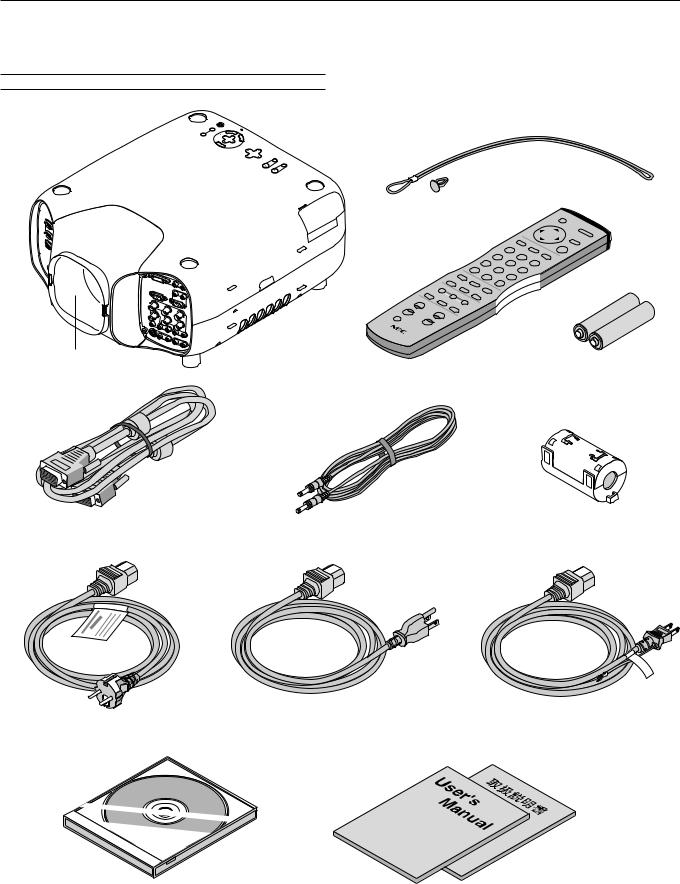
What's in the Box?
Make sure your box contains everything listed. If any pieces are missing, contact your dealer.
Please save the original box and packing materials if you ever need to ship your GT1150 Projector.
NOTE: Lenses are optional. Order lenses from your NEC dealer.
GT1150 Projector
ECRUOS
|
YBD |
NATS |
RE |
WPO |
|
|
|
|
|
|
|
|
|
||
|
|
/N O |
|
|
S |
UTA |
|
TSU |
|
|
|
|
|
TS |
|
|
JDA |
|
|
|
|
|
PM AL |
OTUA |
|
|
|
|
|
||
|
|
|
|
|
|
NA C |
|
|
|
|
|
TC |
|
|
R |
|
|
|
|
LESE |
|
||
|
|
|
|
|
|
||
|
|
|
U |
|
|
|
|
|
|
|
NEM |
|
|
|
|
T |
IGH |
|
N |
|
|
|
R |
T |
|
WO D |
|
|
|
IF HS |
SNLE |
|
|
|
|
|
|
|
|
|
PU |
|
|
TFEL |
OMO Z |
SUCO F
String and rivet
Lens hood cap
Remote control and batteries (AAA x 2)
RGB signal cable
Ferrite clamp core for a commercially
(15-Pin Mini D-Sub To 15-Pin Mini D-Sub connector) Remote cable available BNC cable
(For RGB 2 connector. See page E-27 for installation instructions.)
Power cable for Europe (AC 220-240V)
Power cable for North America (AC 120V) |
Power cable for Japan (AC 100V) |
|
User’s manuals |
CD-ROM |
(Japanese and English/German) |
|
E – 1
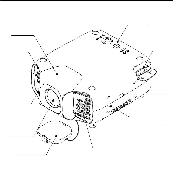
Getting to Know Your GT1150 Projector
Lens hood
Remote sensor
ECRUO S
YB |
DN |
R |
|
|
EW |
|
|
|
AT |
OP |
|
|
S/N |
|
|
|
O |
S |
|
TS |
|
UT |
|
|
ATS |
|
|
UJD |
|
P |
|
OTUA |
A |
|
|
|
|
|
MAL |
|
|
L |
|
|
|
ECNAC |
|
|
|
|
R |
|
|
TC |
E |
|
|
N |
|
|
|
|
T |
|
|
EL |
E |
|
|
ES |
|
|
|
UN |
|
|
|
EM |
|
TH |
|
NW |
|
IGR |
|
|
|
|
TIF |
OD |
|
|
|
|
|
|
HS |
SN |
|
|
|
EL |
|
P |
|
T |
MO |
U |
|
FEL |
OZ |
SUCO
F
Controls
PC Card slot
Open the cover to access the PC card slot.
Terminal panel (Left)
IN |
P |
N |
CC |
I |
O |
|
N |
|
T |
|
R |
|
O |
|
L |
|
|
REM |
O |
OTE |
2 |
|
U |
|
T |
|
|
O |
|
U |
R |
T |
E |
|
M |
|
O |
|
T |
|
E1 |
|
|
S |
|
C |
|
, |
|
T |
|
R |
|
IG |
|
G |
|
E |
|
R |
|
A |
|
C |
|
IN |
AC INPUT
Connect the supplied power cable’s three-pin plug here.
Lens (optional)
Lens hood cap
|
|
|
DVI |
|
|
|
|
|
|
|
|
|
|
|
|
|
|
L/M |
|
|
|
|
|
|
|
|
|
|
|
ONO |
R |
|
|
|
|
|
|
|
|
L/M |
|
|
|
|
|
MON |
|
|
|
|
ONO |
|
||
|
|
|
ITOR |
OUT |
|
|
|
|
R |
|
|
|
|
|
|
|
|
|
R |
|
|
R |
|
|
|
|
|
|
|
GB 1 |
|
|
GB 2 |
|
|
|
|
|
|
|
|
|
|
|
|
|
R/Cr |
|
|
|
|
|
|
|
VIDE |
O 1 |
|
|
|
|
|
G/Y |
|
|
|
|
|
|
|
|
|
|
|
|
|
|
|
|
|
|
|
|
|
|
|
|
B/Cb |
VIDEO |
2 |
|
L/M |
ONO |
|
H |
/HV |
|
|
|
|
|
|
|
|
R |
|
|
|
|
|
|
|
|
|
|
|
|
|
|
V |
|
|
|
|
|
|
|
|
|
|
|
|
|
|
|
L/M |
|
|
|
|
|
|
|
|
|
|
|
ONO |
R |
|
|
|
|
|
|
|
|
|
|
|
|
L/ |
|
|
|
|
S- |
|
|
|
|
|
|
|
|
|
|
VIDE |
O |
|
|
|
|
MON |
O |
|
|
|
|
|
|
|
|
|
R |
|||
|
|
|
|
|
|
|
|
|
||
|
|
|
|
|
|
|
|
AUDIO |
OUT |
|
|
|
|
|
|
|
|
|
|
|
|
Remote sensor
Ventilation (outlet)
Built-in Security Slot (  )*
)*
Foot (four)
Rotate to fine-adjust the height of each foot.
Terminal panel (Right)
*NOTE: Slot for Kensington MicroSaver Security System This security slot supports the MicroSaver® Security System.
MicroSaver® is a registered trademark of Kensington Microware Inc. The logo is trademarked and owned by Kensington Microware Inc.
E – 2
Depression for foot (4 locations)
FOCUS
ZO |
LEF |
|
U |
OM |
T |
|
P |
|
|
LE |
|
|
|
NS |
SH |
|
DO |
|
IFT |
|
|
RIG |
|
|
WN |
|
|
|
|
|
HT |
|
ME |
|
|
|
|
NU |
|
|
|
E |
S |
|
|
|
N |
EL |
|
|
|
T |
EC |
|
|
|
E |
T |
|
|
|
R |
|
|
|
|
|
CANCE L |
|
|
S |
|
|
|
OUR |
|
|
|
|
|
CE |
L |
|
|
A |
|
AM |
P |
A |
|
|
|
UT |
|||
|
STAT |
DJU |
O |
|
|
|
ST |
||
|
US |
ON/ |
|
|
|
PO |
|
|
|
|
STA |
|
|
|
|
WE |
ND |
BY |
|
|
R |
|
|
|
Speaker (Left)
Remote sensor
Speaker (Right)
Air filter
Ventilation (inlet)
Remote sensor
Carrying handle
Lamp cover
E – 3
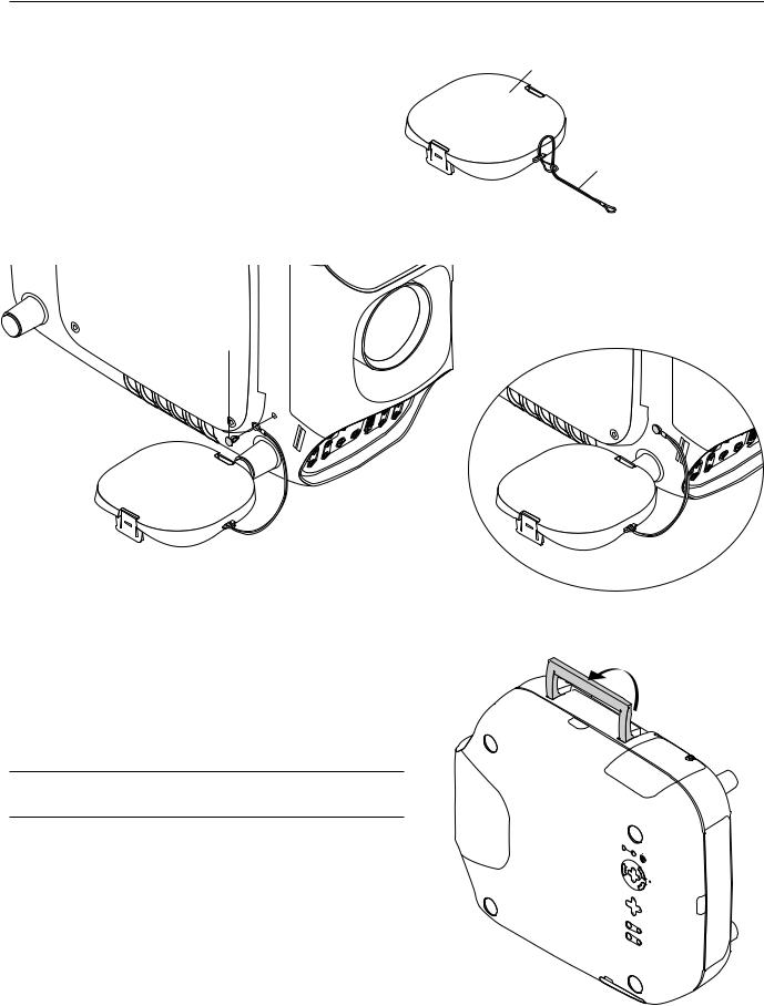
Attaching the lens hood cap to the lens hood with the supplied string and rivet
1. Thread the string through the hole on the lens hood cap. |
Lens hood cap |
String
2. Use the rivet to attach the string to the bottom of the projector.
Rivet
|
|
|
|
|
R |
|
|
|
/L |
|
G |
|
|
|
|
B |
|
|
-S |
|
M |
/G |
1 |
|
IV |
/L |
N |
Y |
|
|
D |
M |
O |
|
|
E |
O |
|
|
|
|
O |
|
N |
R |
/H |
|
|
|
O |
|
||
|
|
R |
|
VH |
|
|
|
|
/B |
|
|
|
|
|
|
|
|
|
|
/L |
|
bC |
|
|
O |
M |
V |
|
|
|
N |
|
|
|
|
|
O |
|
|
|
|
|
R |
|
|
|
|
Carrying the Projector
Always carry your projector by the handle.
Ensure that the power cable and any other cables connecting to video sources are disconnected before moving the projector.
When moving the projector or when it is not in use, cover the lens with the lens hood cap.
CAUTION:
Do not put the projector on its side when the lamp is on.
Doing so may cause damage to the projector.
SOURCE |
BY |
AUTO ADJUST |
ON/STAND |
NU |
|
|
ME |
SELECT |
LE |
|
CN |
|
|
|
AC |
|
|
R |
|
|
ENTE |
|
RIGHT |
|
UP |
SHIFT |
|
|
LENS |
DOWN |
|
LEFT |
|
|
|
ZOOM |
|
|
FOCUS |
LAMP STATUS POWER
E – 4
Top Features
8
FOCUS
ZOOM
10
9
LEFT |
|
|
6 |
5 |
4 |
|
UP |
|
|||
|
|
|
|||
LENS |
SHIFT |
|
|
|
3 |
|
|
|
|
||
DOWN |
|
RIGHT |
|
2 |
|
|
|
|
M |
|
|
|
|
|
|
|
|
E |
|
|
|
|
|
|
|
|
N |
|
|
|
|
|
|
|
SELECT |
U |
|
|
|
|
|
T |
|
|
|
|
|
|
|
|
E |
|
|
|
|
|
|
|
|
N |
|
|
|
|
|
|
|
|
E |
|
|
|
|
|
|
|
|
R |
|
|
|
|
|
|
|
|
7 |
C |
|
|
|
|
|
|
|
|
ANCEL |
|
|
|
|
|
|
|
L |
|
|
|
|
|
|
|
|
A |
|
|
|
|
|
A |
|
|
M |
P |
|
|
|
|
|
||
|
|
|
|
A |
|
U |
|
|
|
|
|
|
|
|
T |
||
|
S |
|
|
|
D |
|
O |
|
|
|
|
|
|
JUS |
|||
|
T |
|
|
|
|
|
T |
|
|
|
A |
|
|
|
|
|
|
|
|
T |
|
|
|
|
|
|
|
|
U |
|
|
|
|
|
|
|
|
S |
|
O |
|
|
|
|
|
|
|
|
|
|
|
|
|
|
|
P |
|
N/ |
|
|
|
|
|
|
|
S |
|
|
|
|
|
|
|
O |
|
T |
|
|
|
|
|
|
W |
|
|
A |
|
|
|
|
|
ER |
|
N |
|
|
|
|
|
|
|
|
D B |
|
|||
|
|
|
|
|
|
|
Y |
|
11
12 1
13
SOURCE
1. Power Button (ON / STAND BY)
Use this button to turn the power on and off when the power is supplied and the projector is in standby mode.
NOTE: To turn off the projector, press and hold this button for a minimum of two seconds.
2. Auto Adjust Button (RGB only)
Use this button to adjust Position-H/V and Pixel Clock/Phase for an optimal picture. Some signals may not be displayed correctly or take time to switch between sources.
3. Source Button
Use this button to select a video source such as a PC, VCR, DVD player or PC Card Viewer (PC card).
Each time this button is pressed, the input source will change as follows:
→ RGB1 → RGB2 → Video1 → Video2 → S-Video → DVI digital → DVI analog → PC Card Viewer
If no input signal is present, the input will be skipped.
4.Menu Button
Displays the menu.
5.Select ▲▼§ © / Volume (+) (-) Buttons
▲▼: Use these buttons to select the menu of the item you wish to adjust.
When no menus appear, these buttons work as a volume control.
§ ©: Use these buttons to change the level of a selected menu item.
A press of the © button executes the selection.
When the menus or the Viewer tool bar is not displayed, these § © buttons can be used to select a slide, or to move the cursor in Folder List or Slide List.
When the pointer is displayed, these ▲▼§ © buttons move the pointer.
6. Enter Button
Executes your menu selection and activates items selected from the menu.
7. Cancel Button
Press this button to exit “Menus”. Press this button to return the adjustments to the last condition while you are in the adjustment or setting menu.
8 Lens Shift Button
Adjust the lens offset by shifting the projected image position horizontally and / or vertically.
9 Zoom Button
Zoom the lens in and out.
10 Focus Button
Adjust the lens focus.
11. Lamp Remaining Indicator
Indicates the lamp remaining amount. See the Lamp Light Messages on page E-62 for more details.
12. Status Indicator
When this is lit red (orange in Eco mode) continually, it‘s warning you that the projection lamp has reached the end of its usable life (1500 hours in High-Bright mode and up to 2000 hours in Eco mode). After this light appears, it is advisable to replace the projection lamp as soon as possible. (See page E-58 or 60). In addition the message "The lamp has reached the end of its usable life. Please replace the lamp." appears continually until the lamp is replaced.
If the projector is in Eco mode or something out of the ordinary takes place, this indicator is lit or blinks. For example, If this light blinks red rapidly, it indicates that the lamp cover is not attached properly or the projector is overheated.
See the Power / Status Light Messages on page E-62 for more details.
13. Power Indicator (  )
)
When this indicator is green, the projector is on; when the indicator is orange, it is in standby mode.
E – 5

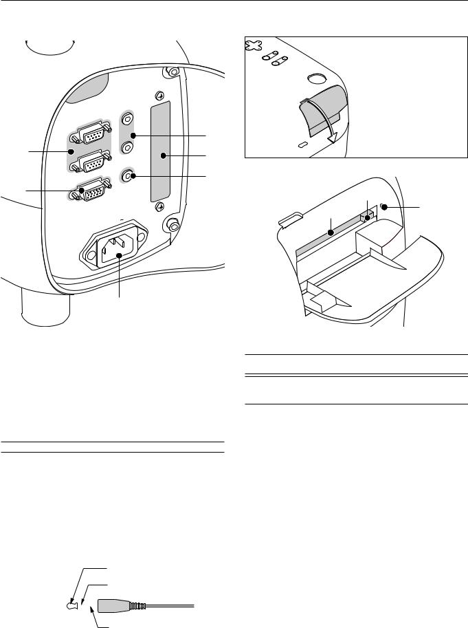
Front Terminal Panel (Right)
DVI |
|
|
1 |
L/MONO |
R |
|
||
MONITOR |
L/MONO |
R |
|
||
5 |
RGB |
|
RGB |
|
|
|
|
|
1 |
|
|
R/Cr |
|
|
VIDEO |
G/Y |
|
8 |
|
B/Cb |
VIDEO |
H/HV |
|
2 |
|
|
9 |
|
V |
10 |
|
|
11 |
|
|
S- |
|
|
VIDEO |
|
|
|
|
OUT |
12
1. DVI Connector
This connector can be used to accept digital or analog signal output from a computer with a DVI connector.
2. DVI Audio Input Jacks (RCA)
These are the left channel and the right audio inputs for stereo sound coming from the equipment connected to a computer with DVI output.
L/MONO
This is your left channel audio input for stereo sound from the equipment connected to a computer with DVI output.
The L/MONO jack also serves as your monaural audio input.
R
This is your right channel audio input for stereo sound from the equipment connected to a computer with DVI output.
3. RGB 2 Connector (Mini D-Sub 15 pin)
Connect your PC, Macintosh, DVD player with Y/Cb/Cr outputs or other
RGB equipment. The optional Component V. Cable is required for Y/
Cb/ Cr input connection.
NOTE: The RGB2 connector does not support the Switcher Control mode.
4. RGB 2 Audio Input Jacks (RCA)
L/MONO
This is your left channel audio input for stereo sound coming from the RGB Input 2 source.
This also serves as your monaural audio input.
R
This is your right channel audio input for stereo sound from the RGB Input 2 source.
5. MONITOR OUT Connector (Mini D-Sub 15 pin)
You can use this connector to loop your computer image an external monitor from either the RGB 1,
RGB 2 or DVI analog input source.
2 |
6. RGB 1 Input Connectors (BNC) |
|
|
Connect R,G,B,H (Horizontal sync) and V (Vertical |
|
4 |
sync) outputs of external equipment such as the NEC |
|
ISS-6020Switcher. |
||
|
If using a component with a combined sync (SYNC) |
|
3 |
output, connect it to the H/V terminal. When using |
|
luminance and color-difference signals of HDTV and |
||
DVD, connect Pr/Cr to the R,Y to the G and Pb/Cb |
||
|
||
|
to the B input of the projector. |
6 |
7. RGB 1 Audio Input Jacks (RCA) |
|
L/MONO |
|
This is your left channel audio input for stereo sound |
|
coming from the RGB Input 1 source. |
7 |
This also serves as your monaural audio input. |
R |
|
|
This is your right channel audio input for stereo sound |
from the RGB Input 1 source.
13
8. VIDEO 1 Input Connector (BNC)
Connect a VCR, DVD player, laser disc player, or document camera here to project video.
9. VIDEO 2 Input Connector (RCA)
Connect a VCR, DVD player, laser disc player, or document camera here to project video.
10.VIDEO Audio Input Jacks (RCA)
L/MONO
This is your left channel audio input for stereo sound coming from the
VIDEO 1 or VIDEO 2 source.
This also serves as your monaural audio input.
R
This is your right channel audio input for stereo sound from the VIDEO
1or VIDEO 2 source.
11.S-VIDEO Input Connector (Mini DIN 4 pin)
Here is where you connect the S-Video input from an external source such as a VCR or laser disc player.
NOTE: S-Video provides more vivid color and higher resolution than the traditional composite video format.
12.S-VIDEO Audio Input Jacks (RCA)
L/MONO
This is your left channel audio input for stereo sound coming from the
S-VIDEO source.
This also serves as your monaural audio input.
R
This is your right channel audio input for stereo sound from the S- VIDEO source.
13.AUDIO OUT Jacks (RCA)
You can use this connector to output sound from the currently selected input source (RGB 1, RGB 2, VIDEO 1, VIDEO 2, S-VIDEO or DVI
[digital/analog] ). Output sound level can be adjusted in accordance with the sound level of the internal speaker.
E – 6
Front Terminal Panel (Left)
|
|
IN |
|
|
|
R |
EM |
O |
TE |
|
|
|||
|
2 |
|
||
|
|
|
||
1 |
CONTROL |
|
|
|
|
OUT |
|||
|
|
|||
|
OUT |
|
|
|
2 |
SC, |
TRIGGER |
||
|
|
|
||
|
REMOTE |
|
|
|
|
IN |
|
|
|
6
PC Card Viewer
RI |
|
DOWN |
|
|
SHIFT |
LENS |
|
|
|
|
|
UP |
|
LEFT |
ZOOM |
FOCUS
Push down to open the PC
Card Slot cover.
3
5
4
8
7 |
9 |
1.PC CONTROL Connectors (Mini D-Sub 9 pin)
For system expansion such as PC-Control.
IN: connect to the external equipment such as PC.
OUT: for daisy-chaining multiple projectors and operating them with the same external equipment. To do so, connect to a second projector’ s IN terminal to relay the input at the IN terminal of the first projector until all the projectors are connected.
2.REMOTE 1 Connector (Mini D-Sub 15 pin)
This terminal allows external control of the projector from either the Switcher or from an external control. When the Switcher is used, connect to the REMOTE 1 terminal on the back of the Switcher.
NOTE: This projector is compatible with the ISS-6020 Switcher.
3. REMOTE 2 Mini Jacks
IN: wired remote control input.
OUT: for daisy-chaining multiple projectors and operating them with the same remote control. To do so, connect to a second projector’ s IN terminal to relay the input at the IN terminal of the first projector until all the projectors are connected.
4. SC. TRIGGER Mini Jack
Screen TriggerWhen the GT1150 is powered ON the screen trigger output sends a low voltage trigger to the screen controller and the screen will go down.
Stereo mini cable |
|
|
Tip (12V) |
|||
(not supplied) |
|
|
Ring (0V) |
|||
|
|
|
|
|||
|
|
|
|
|
|
|
|
|
|
|
|
|
|
|
|
|
|
|
|
|
|
|
|
|
|
|
|
Sleave (ground. 0V)
When the GT1150 is powered OFF the screen trigger stops sending a low voltage trigger to the screen controller and the screen will go up.
NOTE: Screen Controllers are supplied and supported by screen manufactures. This option is not included with the GT1150 projector.
NOTE: Do not use this jack for anything other than intended use. Connecting the wired remote control to the SC. TRIGGER Mini Jack causes damage to the remote control.
5. Slot for LAN Board (Optional)
Use this connector to control the projector on a LAN. The optional LAN kit is required when this connector is used. See the instructions included with the optional LAN kit.
6. AC IN
Connect the supplied power cable’s three-pin plug here.
Three types of power cable are supplied with this LCD projector: threepin type for U. S. A. and Canada.Two-pin type for Germany and Japan.
7.PC Card Slot
Insert a PC card here.
8.PC Card Eject Button
Press to eject a PC card.
9.PC Card Access Indicator
Lights while accessing a PC card.
E – 7
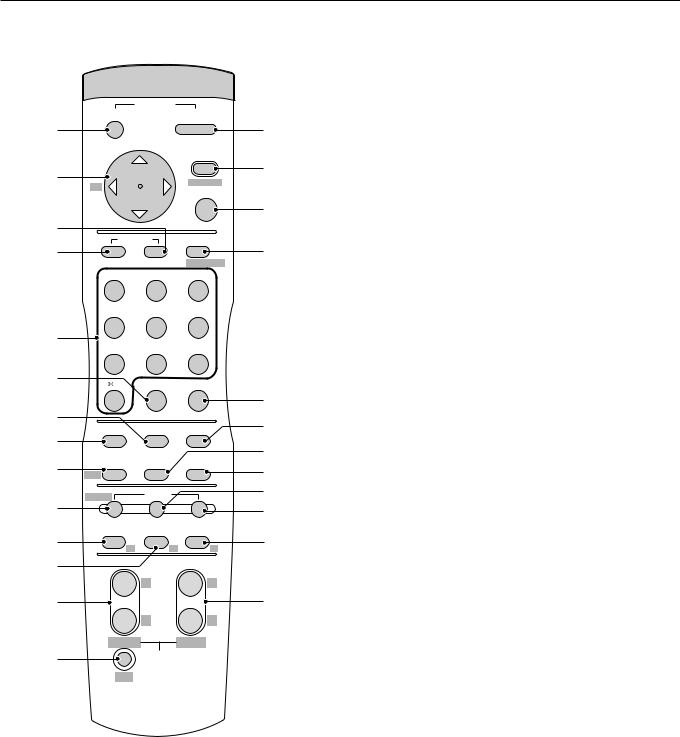
Remote Control Features
|
OFF |
POWER |
ON |
|
|
2 |
|
1 |
|||
|
|
|
|||
|
|
|
MENU |
3 |
|
5 |
BS - |
+ |
ADDRESS |
||
|
|||||
|
ENTER |
|
|||
|
|
|
|
||
6 |
|
|
|
4 |
|
ADJUST |
IMAGE |
|
|||
7 |
8 |
||||
PICTURE WHITE BAL. PROJECTOR |
|||||
|
|
||||
|
ABC |
DEF |
GHI |
|
|
|
1 |
2 |
3 |
|
|
|
JKL |
MNO |
PQR |
|
|
9 |
4 |
5 |
6 |
|
|
STU |
VWX |
YZ? |
|
||
10 |
7 |
8 |
9 |
|
|
,. |
UNDO |
CANCEL |
|
||
12 |
0 |
|
|
11 |
|
TEST |
INFO. |
HELP |
14 |
||
13 |
|||||
|
|
|
15 |
||
17 |
POSITION |
PIXEL |
AUTO |
||
16 |
|||||
LENS |
|
|
|||
20 |
SHUTTER |
MUTE |
|
18 |
|
PICTURE |
SOUND |
OSD |
19 |
||
|
|
||||
21 |
KEYSTONE |
AMPLITUDE ENTRYLIST |
23 |
||
R |
G |
B |
|||
22 |
|
MAGNIFY |
|
||
|
+ |
+ |
|
||
|
|
|
|||
24 |
|
- |
- |
25 |
|
|
|
|
|||
26 |
FOCUS |
ZOOM |
|
||
|
LENS |
|
|
||
CTL
1. POWER ON Button
Press this button to turn on the projector when the power is supplied and the projector is in standby mode.
2. POWER OFF Button
Press and hold this button for a minimum of two seconds to turn off the projector.
3. MENU Button
Press to display the main menu.
While pressing and holding CTL, press this button to display the Remote Control ID dialog box to specify the remote control ID. See page E-33.
4. ENTER Button
Executes the menu selection and activates items selected from the menu. When the slider or dialog box is displayed:
Pressing this button confirms adjustments/setting and returns to the previous menu display.
5. Select (Up/Down/Left/Right) Button
▲▼: Use these buttons to select the menu of the item you wish to adjust.
When no menus appear, these buttons work as a volume control.
§ ©: Use these buttons to change the level of a selected menu item.
A press of the © button executes the selection.
When the menus or the Viewer tool bar is not displayed, these § © buttons can be used to select a slide, or to move the cursor in
Folder List or Slide List.
When the pointer is displayed, these ▲▼§ © buttons move the pointer.
See page E-35 for displaying the pointer.
Pressing and holding CTL, then pressing § button works as a Back Space key in the entry screen.
Pressing and holding CTL, then pressing this button moves the menu, slider, toolbar or dialog box.
6. ADJUST WHITE BAL Button
Press to display the color adjustment screen. Pressing this button sequentially selects "Color Temperature" → "White Balance" → "Switcher
Gain".
7.ADJUST PICTURE Button
Press to display the Picture screen.
8.IMAGE/PROJECTOR Button
Press to display the Image Options screen.
Pressing this button sequentially selects "Gamma Correction" → "Aspect Ratio" → "Noise Reduction" → "Color Matrix" → "Resolution" →
"Video Filter" → "Overscan" → "Clamp Timing” → "Y/C Delay" → "YTR
Adjustment" → "CTR Adjustment" → "HD Delay".
While pressing and holding CTL, pressing this button rotates "On/Off Timer" → "Sleep Timer" → "Menu" → "Setup" → "Link Mode" → "Switcher Control" → "LAN mode" (optional).
9. Source / Alphanumeric Buttons
Press to select input or to name a signal.
1 .................. |
Selects RGB 1 input. |
2 .................. |
Selects RGB 2 input. |
3 .................. |
Selects VIDEO 1 input. |
4 .................. |
Selects VIDEO 2 input. |
5 .................. |
Selects S-VIDEO 1 input. |
6 .................. |
Selects DVI digital input. |
7 .................. |
Selects DVI analog input. |
8 .................. |
Selects PC Card Viewer. |
9 .................. |
Selects RGB1 (VIDEO) input |
0 .................. |
Selects RGB2 (S-VIDEO) input |
E – 8
10. UNDO
Press to return the adjustments and settings to the previous condition.
While pressing and holding CTL, pressing this button clears the entire menus or adjustment/setting screen. At this time the adjustments/settings are stored in memory except the items on the setting screen with "OK" and "Cancel" buttons such as the Menu and the Setup screen.
11. CANCEL
Press to exit the menu.
Press this button with CTL to return to the previous menu without closing adjustment/setting screen while the menus appear. This feature allows you to adjust or set several items concurrently.
12. INFO
Displays the Information screen.
13. TEST
Press to display the test pattern. Pressing this button sequentially selects nine test patterns.
14. HELP
Provides online help.
15. PIXEL
Displays the Position/Clock screen to adjust the clock and phase.
16. AUTO (RGB only)
Press to adjust Position-H/V and Pixel Clock/Phase for an optimal picture.
17. POSITION
Press to display the Position/Clock screen.
While pressing and holding CTL, pressing this button displays the Lens
Shift adjustment screen.
18. MUTE SOUND
Turns off the sound for a short period of time. Press again to restore the sound.
19. MUTE OSD
Press to turn off the on-screen display. Press again to restore the onscreen display.
NOTE: You can also turn off the on-screen display forcefully by pressing and holding CTL and then pressing MUTE OSD (Forced On-Screen Mute Mode) ; doing this again restores it. In this case any adjustment will still change the projector's memory settings. This mode is available even when input is switched to another or the power is turned off the main power.
20. MUTE PICTURE
Press to turn off the picture for a short period of time. Press again to restore the picture.
21. KEYSTONE (R)
Press to display the Keystone Correction screen.
When the test pattern is displayed, while pressing and holding CTL, pressing this button displays a red test pattern.
22.AMPLITUDE (G)
Service personnel only.
When the test pattern is displayed, while pressing and holding CTL, pressing this button displays a green test pattern.
23.ENTRY LIST (B)
Press to display the Entry List screen.
When the test pattern is displayed, while pressing and holding CTL, pressing this button displays a blue test pattern.
24. FOCUS (+/–)
While pressing and holding CTL, pressing this button allows you to adjust the lens focus.
25.MAGNIFY/ZOOM (+/–)
Magnify the size of a target portion.
While pressing and holding CTL, pressing this button allows you to zoom the lens in and out.
26.CTL
Used in conjunction with other buttons, similar to a shift key on a computer.
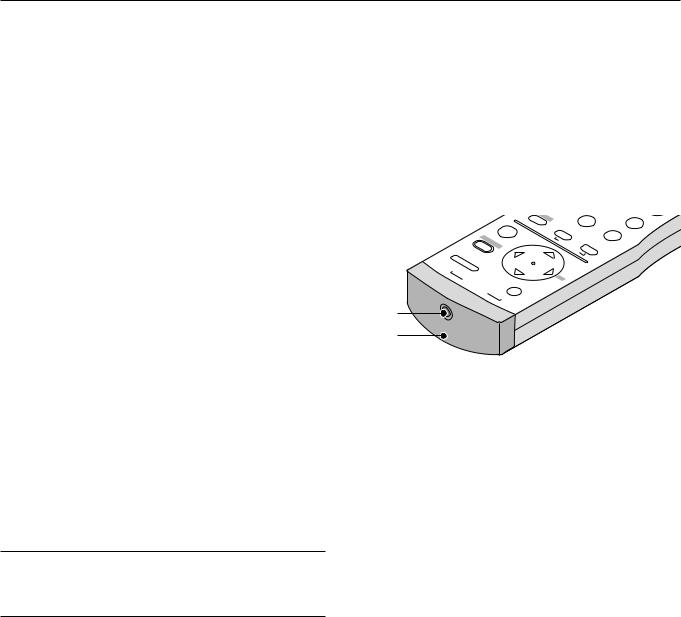
27. Remote Jack
Connect your remote control cable here for wired operation.
28. Infrared Transmitter
Direct the remote control toward the remote sensor on the projector cabinet.
|
|
|
J |
|
|
|
M |
|
|
T |
|
|
|
OR |
|
|
2 |
|
|
||
|
|
IMAGE |
P |
|
|
|
|
4 |
S |
|
|
|
. |
BAL |
DEF |
|
JKL |
|
|||
|
|
|
|
|
WHITE |
|
|
|
|
|
SS |
ENTERD |
|
|
|
|
ABC |
1 |
|
|
|
|
D |
|
|
|
|
|
|
|
|
|
E |
|
|
ADJUST |
PICTURE |
|
|
|
|||
MENU |
A |
|
|
|
|
|
||||
|
|
|
|
|
|
|
|
|
||
|
+ |
|
|
|
|
|
|
|
|
|
|
|
|
|
|
|
|
|
|
|
|
ON |
|
|
- |
|
|
|
|
|
|
|
POWER |
|
|
|
BS |
|
|
|
|
|
|
OFF |
|
|
|
|
|
|
|
|
|
|
|
|
|
|
|
|
|
|
|
|
|
27
28
E – 9

Remote Control Precautions
•The remote control system may not function when direct sunlight or strong illumination strikes the remote control sensor of the main unit, or when there is an obstacle in the path.
•When remote control buttons are pressed and held, projector’s function keys may not operate.
•Do not subject to strong shock.
•Do not allow water or other liquid to splash on the remote control. If the remote control gets wet, wipe it dry immediately.
•Avoid exposure to heat and steam.
•Remove the batteries from the remote control when the remote control is not going to be used for a long period.
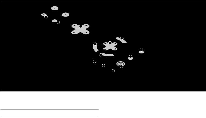
Remote Control Battery Installation
Installing the Remote Control Batteries
When it comes time to replace the batteries, two "AAA" type will be required.
1. Press and open the cover.
Operating Range for Wireless Remote Control
The infrared signal operates by line-of-sight up to a distance of approximately 7m (20 feet) and a 60 degree angle of the remote sensor.
The projector will not function if there are objects between the remote sensor and the remote control or if strong light falls on the remote sensor. Weak batteries will also prevent the projector from operating properly.
Remote sensors on the projector cabinet
30˚
|
7m |
Side View |
30˚ |
|
Remote control
30˚
2. Align and insert the batteries according to the (+) and (-) indica-
7m
tions inside the case.
30˚
NOTE: You cannot operate the projector using the remote control if:
• The remote control ID is not set to [None].
3. Replace the cover. • The remote ID is not the same as the projector ID.
See page E-33 for setting remote ID and page E-49 for setting projector ID.
E – 10
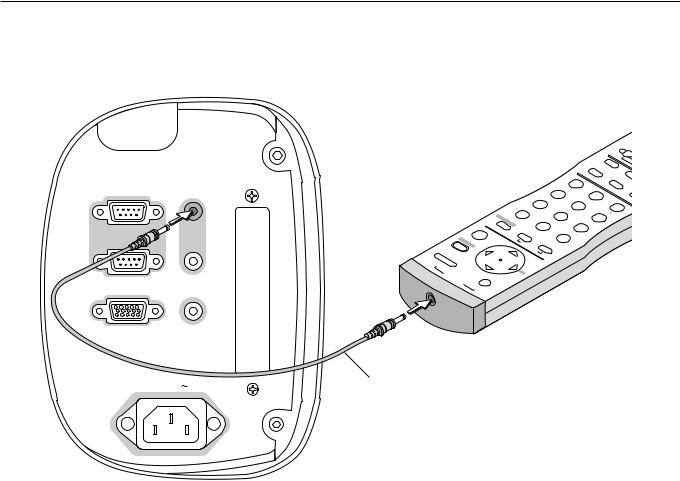
Using the Remote Control in Wired Operation
Connect one end of the supplied remote cable to the REMOTE 2 IN mini jack and the other end to the remote jack on the remote control.
IN |
IN |
PC CONTROL |
REMOTE |
|
2 |
OUT |
OUT |
REMOTE 1 |
SC, TRIGGER |
|
AC IN |
|
|
|
|
|
|
|
|
|
|
|
|
|
|
|
|
|
|
|
|
|
|
|
|
|
|
|
|
T |
|
|
|
|
|
|
|
|
|
|
|
|
|
|
|
|
|
|
|
|
|
|
|
|
|
HELP |
AUTO |
||
|
|
|
|
|
|
|
|
|
|
|
|
|
|
|
|
|
|
|
|
|
CANCEL |
|
|
IXEL |
||||
|
|
|
|
|
|
|
|
|
|
|
|
|
|
|
|
|
|
|
|
|
|
|
|
. |
INFO |
|||
|
|
|
|
|
|
|
|
|
|
|
|
|
|
|
|
|
YZ? |
9 |
|
|
UNDO |
|
T |
|||||
|
|
|
|
|
|
|
|
|
|
|
|
|
|
|
6 |
|
|
|
|
|
|
|
8 |
|
|
S |
||
|
|
|
|
|
|
|
|
|
|
|
|
|
PQR |
|
|
|
|
|
|
VWX |
|
|
0 |
|||||
|
|
|
|
|
|
|
|
|
|
|
|
|
|
|
|
|
|
|
|
|
|
|
||||||
|
|
|
|
|
|
|
|
|
|
|
3 |
|
|
|
|
|
|
|
|
|
|
|
. |
|||||
|
|
|
|
|
|
R |
TO |
|
GHI |
|
|
|
|
|
MNO |
5 |
|
|
|
|
7 |
|
||||||
|
|
|
|
|
|
|
|
OJEC |
|
|
|
|
|
2 |
|
|
|
|
|
STU |
|
|
||||||
|
|
|
|
|
E |
|
|
PR . |
|
|
|
|
|
|
|
|
|
4 |
|
|
||||||||
|
|
|
|
|
AG |
|
|
|
|
DEF |
|
|
|
|
|
|
|
|
|
|
||||||||
|
|
|
|
|
|
IM |
|
|
L |
BA |
|
|
|
|
|
|
|
JKL |
|
|
|
|||||||
|
|
|
ENTERDR |
|
|
|
|
|
|
|
ST |
ITE |
|
|
|
UR ABC |
1 |
|
|
|
|
|
||||||
|
|
S |
|
|
|
|
|
|
|
H |
W |
|
|
|
|
|
|
|||||||||||
|
|
|
ES |
AD |
|
|
|
|
|
|
|
|
JU |
|
|
E |
|
T |
|
|
|
|
|
|
|
|
|
|
|
MENU |
|
|
|
|
|
|
|
|
|
|
|
|
|
IC |
|
|
|
|
|
|
|
|
|||||
|
|
|
|
|
|
|
|
|
|
|
D |
|
|
|
|
|
|
|
|
|
|
|
|
|
||||
|
|
|
|
|
+ |
|
|
|
|
|
|
|
A |
|
|
|
|
|
P |
|
|
|
|
|
|
|
|
|
|
|
|
|
|
|
|
|
|
|
|
|
|
|
|
|
|
|
|
|
|
|
|
|
|
|
|
|
|
N |
O |
|
|
|
|
|
|
|
- |
|
|
|
|
|
|
|
|
|
|
|
|
|
|
|
|
|
|
|
|
|
|
|
|
|
|
|
|
|
|
|
|
|
|
|
|
|
|
|
|
|
|
|
|
|
|
||
|
R |
|
|
|
|
|
|
|
|
|
BS |
|
|
|
|
|
|
|
|
|
|
|
|
|
|
|
|
|
|
|
|
|
|
|
|
|
|
|
|
|
|
|
|
|
|
|
|
|
|
|
|
|
|
|
|
|
|
|
E |
|
|
|
|
|
|
|
|
|
|
|
|
|
|
|
|
|
|
|
|
|
|
|
|
|
|
|
|
W |
O |
|
|
|
|
|
|
|
|
|
|
|
|
|
|
|
|
|
|
|
|
|
|
|
|
|
|
|
|
P |
F |
|
|
|
|
|
|
|
|
|
|
|
|
|
|
|
|
|
|
|
|
|
|
|
|
|
|
|
|
|
F |
O |
|
|
|
|
|
|
|
|
|
|
|
|
|
|
|
|
|
|
|
|
|
|
|
|
|
|
|
|
|
|
|
|
|
|
|
|
|
|
|
|
|
|
|
|
|
|
|
|
|
|
|
|
Remote cable (supplied)
Terminal panel (Left)
E – 11
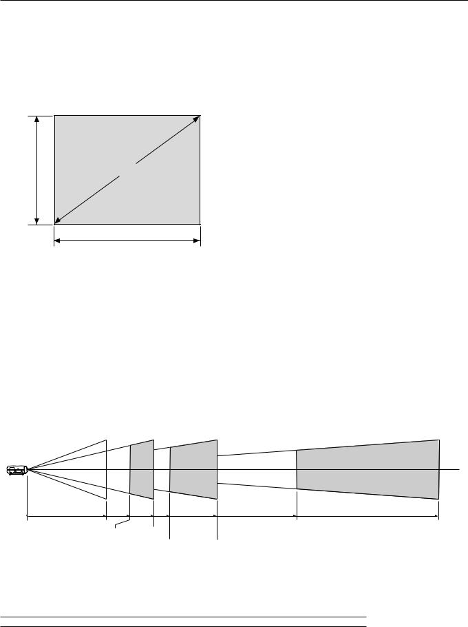
2. INSTALLATION
This section describes how to set up your GT1150 projector and how to connect video and audio sources.
Setting Up Your GT1150 Projector
Your GT1150 Projector is simple to set up and use. But before you get started, you must first:
1.Determine the image size
2.Set up a screen or select a non-glossy white wall onto which you can project your image.
3.Install the optional lens to the projector.
4.Connect the supplied power cable.
5.Set up the projector.
6.Connect a PC, VCR, DVD player, or other equipment.
7.Make settings or adjustments on the projector.
Screen Size and Projection Distance
Applicable lens and throw distance/ List of screen sizes
Height |
Screen size (Diagonal) |
|
Width |
Table of Throw Distances and Screen Sizes for Optional Lenses
List of Screen Sizes
Screen size |
|
Width (H) |
|
|
Height (V) |
|||
|
|
m |
|
feet |
|
m |
|
feet |
40" |
|
0.8 |
|
2.7 |
|
0.6 |
|
2.0 |
60" |
|
1.2 |
|
4.0 |
|
0.9 |
|
3.0 |
80" |
|
1.6 |
|
5.3 |
|
1.2 |
|
4.0 |
100" |
|
2.0 |
|
6.7 |
|
1.5 |
|
5.0 |
120" |
|
2.4 |
|
8.0 |
|
1.8 |
|
6.0 |
150" |
|
3.0 |
|
10.0 |
|
2.3 |
|
7.5 |
200" |
|
4.1 |
|
13.3 |
|
3.0 |
|
10.0 |
250" |
|
5.1 |
|
16.7 |
|
3.8 |
|
12.5 |
300" |
|
6.1 |
|
20.0 |
|
4.6 |
|
15.0 |
400" |
|
8.1 |
|
26.7 |
|
6.1 |
|
20.0 |
500" |
|
10.2 |
|
33.3 |
|
7.6 |
|
25.0 |
Formulas: |
Screen width H (m)= Screen Diagonal (4:3) x 4/5 x 0.0254 |
|||||||
|
Screen height V (m)= Screen Diagonal (4:3) x 3/5 x 0.0254 |
|||||||
|
Screen width H (feet)= Screen size x 4/5 |
|
|
|
||||
|
Screen height V (feet)= Screen size x 3/5 |
|
|
|||||
Lens |
Model |
GT10RL |
|
|
GT13ZL |
GT19ZL |
GT34ZL |
||||
|
Magnification |
1.0 |
|
|
1.3 – 1.6 |
1.8 – 2.4 |
3.4 – 5.2 |
||||
|
40" |
0.8 (m) |
|
2.7 (feet) |
1.1-1.3 (m) |
|
3.5-4.3 (feet) |
1.5-2.0 (m) |
4.8-6.4 (feet) |
– |
– |
|
60" |
1.2 (m) |
|
4.0 (feet) |
1.6-2.0 (m) |
|
5.2-6.4 (feet) |
2.2-2.9 (m) |
7.2-9.6 (feet) |
– |
– |
|
67" |
1.3 (m) |
|
4.4 (feet) |
1.7-2.1 (m) |
|
5.7-7.0 (feet) |
2.5-3.2 (m) |
8.1-10.6 (feet) |
– |
– |
|
72" |
1.4 (m) |
|
4.7 (feet) |
1.9-2.3 (m) |
|
6.1-7.5 (feet) |
2.6-3.5 (m) |
8.7-11.4 (feet) |
– |
– |
(Diagonal) |
80" |
1.6 (m) |
|
5.3 (feet) |
2.1-2.6 (m) |
|
6.9-8.5 (feet) |
2.9-3.9 (m) |
9.6-12.8 (feet) |
5.5-8.5 (m) |
18.1-27.7 (feet) |
84" |
1.7 (m) |
|
5.5 (feet) |
2.2-2.7 (m) |
|
7.1-8.8 (feet) |
3.1-4.1 (m) |
10.2-13.3 (feet) |
5.9-9.0 (m) |
19.3-29.3 (feet) |
|
90" |
1.8 (m) |
|
6.0 (feet) |
2.3-2.9 (m) |
|
7.7-9.5 (feet) |
3.3-4.3 (m) |
10.9-14.3 (feet) |
6.3-9.6 (m) |
20.7-31.4 (feet) |
|
100" |
2.0 (m) |
|
6.7 (feet) |
2.6-3.3 (m) |
|
8.7-10.7 (feet) |
3.7-4.9 (m) |
12.0-16.0 (feet) |
6.9-10.6 (m) |
22.7-34.6 (feet) |
|
120" |
2.4 (m) |
|
8.0 (feet) |
3.2-3.9 (m) |
|
10.4-12.8 (feet) |
4.4-5.9 (m) |
14.4-19.2 (feet) |
8.3-12.7 (m) |
27.2-41.6 (feet) |
|
Size |
|
|
|||||||||
150" |
3.0 (m) |
|
10.0 (feet) |
4.0-4.9 (m) |
|
13.0-16.0 (feet) |
5.5-7.3 (m) |
18.0-24.0 (feet) |
10.4-15.8 (m) |
34.0-52.0 (feet) |
|
180 |
3.7 (m) |
|
12.1 (feet) |
4.7-5.8 (m) |
|
15.5-19.1 (feet) |
6.7-8.8 (m) |
22.1-28.8 (feet) |
12.8-19.3 (m) |
42.1-63.4 (feet) |
|
Screen |
|
|
|||||||||
200" |
4.1 (m) |
|
13.3 (feet) |
5.3-6.5 (m) |
|
17.3-21.3 (feet) |
7.3-9.8 (m) |
24.0-32.0 (feet) |
13.8-21.1 (m) |
45.3-69.3 (feet) |
|
210" |
4.3 (m) |
|
14.2 (feet) |
5.5-6.8 (m) |
|
18.1-22.4 (feet) |
7.9-10.3 (m) |
25.8-33.7 (feet) |
15.0-22.6 (m) |
49.2-74.0 (feet) |
|
240" |
4.9 (m) |
|
16.2 (feet) |
6.3-7.8 (m) |
|
20.8-25.6 (feet) |
9.0-11.7 (m) |
29.6-38.5 (feet) |
17.1-25.8 (m) |
56.3-84.7 (feet) |
|
|
|
|
|||||||||
|
250" |
5.1 (m) |
|
16.7 (feet) |
6.6-8.1 (m) |
|
21.7-26.6 (feet) |
9.1-12.2 (m) |
30.0-40.0 (feet) |
17.3-26.4 (m) |
56.6-86.6 (feet) |
|
270" |
5.6 (m) |
|
18.3 (feet) |
7.1-8.8 (m) |
|
23.4-28.8 (feet) |
10.1-13.2 (m) |
33.3-43.3 (feet) |
19.3-29.1 (m) |
63.4-95.3 (feet) |
|
300" |
6.1 (m) |
|
20.0 (feet) |
7.9-9.8 (m) |
|
26.0-32.0 (feet) |
11.0-14.6 (m) |
36.0-48.0 (feet) |
20.7-31.7 (m) |
68.0-103.9 (feet) |
|
400" |
– |
|
– |
– |
|
– |
– |
– |
27.6-42.3 (m) |
90.6-138.6 (feet) |
|
500" |
– |
|
– |
– |
|
– |
– |
– |
34.5-52.8 (m) |
113.3-173.2 (feet) |
GT10RL (H21.0) GT34ZL (H23.4) – (H25.2)
GT13ZL (H21.3) – (H21.6) |
|
|
Throw distance |
|
|
|
|
GT19ZL (H21.8) – (H22.4) |
|
||
For screen sizes between 40” and 500” not indicated on the above table, use formulas below. |
|||
Projection Distance = Screen Width (H) x Lens Magnification |
|
||
Throw distance for GT10RL lens (m/feet) =H x 1.0 |
(For H between 0.8 m/2.7feet and 6.1 m/20.0 feet) |
||
Throw distance for GT13ZL lens (m/feet) =H x 1.3 |
through |
H x 1.6 |
(For H between 1.1 m/3.5 feet and 9.8 m/32.0 feet) |
Throw distance for GT19ZL lens (m/feet) =H x 1.8 |
through |
H x 2.4 |
(For H between 1.5 m/4.8 feet and 14.6 m/48.0 feet) |
Throw distance for GT34ZL lens (m/feet) =H x 3.4 |
through |
H x 5.2 |
(For H between 5.5 m/18.1 feet and 52.8 m/173.2 feet) |
NOTE: Distances may vary +/-5%.
E – 12
Lens Shift Adjustable Range
Desktop/Front
Vertical
Normal Position
Ceiling/Front
Vertical
Normal Position
0.5V
(0.43V)
Lens Shift Range for Desktop and Ceiling Mount Application
The diagram below shows the location of the image position in the lens. The lens can be shifted within the shaded area as shown using the normal projection position as a starting point.
Note: Lens shift feature is not available on GT10RL (fixed lens)
Maximum Possible Range
for GT19ZL/GT34ZL (GT13ZL):
Up: 0.5V (0.43V) Down: 0.5V (0.43V) Right: 0.25H
Left: 0.25H
(H: width of projected image, V: height of projected image)
Note: If lens is shifted in two directions combined, maximum range in either direction cannot be obtained due to rounded off area near edge of lens. (example: shift up and right)
See diagram below.
|
0.25H |
0.25H |
|
0.5V |
0.50V |
0.50V |
|
(0.43V) |
(0.43V) |
||
(0.43V) |
|||
|
0.50V |
0.50V |
|
Horizontal |
(0.43V) |
(0.43V) |
|
|
|
||
|
0.25H |
0.25H |
|
|
|
Normal projection |
|
|
|
position |
Normal Position
0.25H
E-13
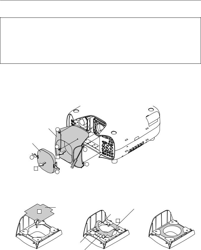
Optional Lens Installation
This section describes how to install the lens.
Before installation
*Determine the optional lens to be used to obtain a desired projection distance. There are four optional lenses available: GT10RL (Fixed short throw lens)
GT19ZL, GT13ZL and GT34ZL (Zoom lens)
*Press the power button (ON/STAND BY) on the projector or POWER OFF button on the remote control, wait ONE minute for the cooling fan to stop, then disconnect the power cable.
Check that the projector has cooled off sufficiently before proceeding.
CAUTION
*The projector and lens contain high-precision parts. Do not induce shock to the projector or the lens.
*Do not touch the lens surface. Doing so can degrade the optical performance.
Preparation: Tools needed for installation:
A hexagonal driver and dust-protective sheets are supplied with the optional lens.
1. Remove the lens hood cap and lens hood.
1 Press and hold the catches on both ends of the lens hood cap, and 2 then remove it.
3 Loosen the 4 screws on the lens hood using the hexagonal driver until the hexagonal driver goes into a freewheeling condition and 4remove the lens hood. The 4 screws are not removable.
Lens hood
3
Lens hood cap
3
3
1 |
4 |
3
2
1
2. Remove the dust-protective sheet and replace with the new one.
1 Remove the dust-protective sheet on the back of the lens hood. 2 Replace it with the dust-protective sheet included with the optional lens.
Place the dust-protective sheet with the two holes side up while warping it. Be careful not to fold the sheet.
|
|
Dust-protective sheet |
|
Dust-protective sheet |
(included with the optional lens) |
1 |
(on the projector) |
Hole |
2
Hole
Side with aluminum |
Completed |
E – 14
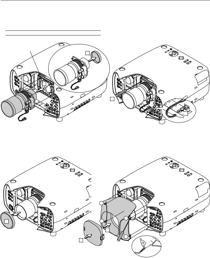
3.Mount the lens unit on the projector and connect the extension cable attached to the projector.
1 Remove the lens cap from the rear end of the lens unit.
2 Insert the lens unit so that the 4 screws on the lens unit are properly lined up with the 4 holes on the lens mount. 3 Secure the 4 screws using the hexagonal driver.
4 Insert the connector of the lens unit fully into the socket of the extension cable attached to the projector.
NOTE: Leave the front lens cap for protection while mounting the lens unit.
Lens mount
2 |
ECR |
UOS |
YB |
DNA TS |
RE |
WOP |
|
|
/NO |
|
|
SUTATS |
OTSUJD |
|
|
|
|
A |
|
|
|
|
TUA |
|
|
|
PMAL |
|
|
|
|
NAC |
|
|
|
CT |
R |
|
|
|
LE SE |
|
|
|
|
|
|
|
|
U |
|
|
|
|
NEM |
|
|
T |
RIGH |
N |
OWD |
|
IFTSH |
||
|
|
|
|
|
|
NS LE |
|
|
UP |
|
FT LE |
1
OMOZ |
|
US |
OCF |
|
YBD |
NAT |
|
RE |
WOP |
|
|
/SN O |
|
|
||
|
|
|
S |
UTA TS |
|
TS |
|
|
|
|
|
OTUJDA |
|
|
|
|
PM AL |
UA |
|
|
|
|
|
ECRUOS |
|
|
|
|
N AC |
R
ELECTS
UNEM
RIGHT |
|
WNDO |
|
|
SHIFT |
LENS |
|
|
|
|
|
UP |
|
FTLE |
ZOOM |
FOCUS
3


 4
4
4. Reinstall the lens hood.
1 Remove the front lens cap from the lens unit.
2 Insert the lens hood so that the grooves on the 4 corners of the lens hood are properly lined up with the 4 catches on the projector. 3 Secure the 4 screws using the hexagonal driver.
This completes installation. 4 If necessary, put the lens hood cap on the lens hood.
ECR UOS
YB |
DNAT/S |
|
RE |
WOP |
|
|
|
NO |
|
|
SUTATS |
TS |
|
|
|
|
|
OTUJD A |
|
|
|
PM AL |
|
UA |
|
|
|
|
|
|
|
|
|
|
NAC |
|
|
|
|
TC |
R |
|
|
|
|
ELE S |
|
|
|
|
|
|
|
|
|
|
U |
|
|
|
|
|
NEM |
|
|
THGIR |
W OD |
|
|
N |
|
|
TFIHS |
|
|
SNEL |
|
PU |
TF EL |
MOOZ |
S |
UCOF |
|
ECR |
UOS |
|
YB |
DNAT/S |
|
RE WO |
|
|
|
|
|
NO |
|
S |
UTATS |
TS U |
|
|
|
|
||
OT |
UAJDA |
|
|
|
P |
|
|
|
|
|
|
|
MAL |
|
|
|
|
|
|
NAC |
R
TCELES
UNEM
THGIR |
|
N |
WO D |
|
|
TFI HS |
SNEL |
|
|
|
|
|
|
|
PU |
|
|
TFEL |
MOOZ |
SUCOF
|
3 |
1 |
3 |
3 |
|
2 |
|
4 |
3 |
Groove |
|
||
|
|
|
|
|
Catch |
E – 15
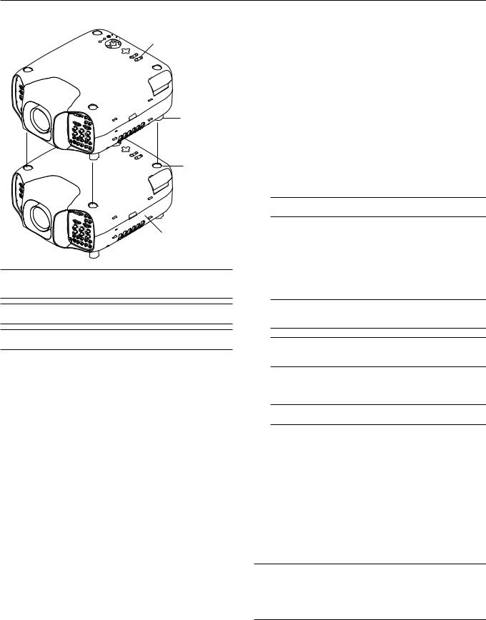
Setting up for Double Stacking in Link Mode
Master projector
Foot
Depression for foot
Slave projector
NOTE: Up to two units can be gravity stacked without external support. In some cases, however, two images will not align on the screen correctly. This will become more apparent when displaying small text and detailed graphics.
CAUTION: To prevent the projectors from falling, install them in a place and fasten them in a way with sufficient strength to support the two projectors.
NOTE: SW 1 Level and SW 2 Level of Switcher Control are not available on Link Mode.
For double stacking, follow the instructions described below.
1) Stacking the Projectors
1-1. Place the projectors at the proper height for best screen to projector relationship. Make sure that all projectors have the same display orientation.
2) Hookup
2-1. Use the supplied RGB signal cable to connect the RGB output of the master projector to the RGB input of the slave projector until all the projectors are connected.
2-2. Next, using a commercially available, bi-directional RS-232C cable connect the PC CONTROL OUT terminal of the master projector to the PC CONTROL IN terminal of the slave projector until all the projectors are connected.
2-3. Turn all the projectors on and roughly make some optical adjustments to each projector.
3) Adjusting and registering signals to be projected in Link mode and stack application.
Signal Data Preparation
3-1. Create data for the master projector and copy data to the slave projector.
3-1-1. Choose one projector as the master. 3-1-2. Turn the master projector on.
3-1-3. Display all desired input signals, make adjustment to each signal, then save all adjustments on the master projector. (Adjustments will be saved automatically.)
3-1-4. Turn the master projector off (standby mode).
3-1-5. Store all the adjustments on a PC card from the master projector.
3-1-5-1. Open the PC Card slot cover to access the PC card slot. Insert a PC card into this slot.
3-1-5-2. Press and hold CANCEL, then press POWER on the top panel of the master projector. The POWER indicator will change to steady green and the PC Card Access indicator will start flashing. After storing data on the PC card, the POWER indicator will change to orange.
3-1-5-3. Remove the PC card from the slot of the master projector.
3-1-6. Transfer the data to the other slave projectors using the PC card so that all the projectors have the same data in memory.
3-1-6-1. Insert the PC card into the slot of a slave projector.
NOTE: Since data in the slave projectors will be lost at this time, make backup copies of them before proceeding.
3-1-6-2. Press and hold ENTER, then press MENU on the top panel of the slave projector. The POWER indicator will change to steady green and the PC Card Access indicator will start flashing to indicate that the data is being copied from the PC card to the slave projector. After copying data to the slave projector, the POWER indicator will change to orange.
3-1-6-3. Remove the PC card from the slave projector.
NOTE: If you select the RGB1 input on the master projector, you must select the same input on the slave projector and the RGB2 on the master projector and the slave projector.
NOTE: After adjusting and registering signals as mentioned above, you must change the input to RGB on the Entry Edit Command window for Link Mode. See "Entry List Edit" on page E-40 for changing to RGB source.
3-1-6-4. Display the desired source.
4) Display the internal crosshatch test pattern.
NOTE: Use a different single color for each projector. Example:
Turn on Green of one projector (master), then Red of the other (slave).
5) Adjusting the lens shift, zoom and focus to clearly display all projected patterns.
5-1. Adjust the Lens Shift using the LENS SHIFT button on the projector cabinet.You can also adjust the Lens Shift by pressing and holding CTL and pressing the POSITION button on the remote control. For Lens Shift Adjustable Range, see page E-13.
5-2. Zoom the lens in and out by using the ZOOM button on the projector cabinet or the remote control.
5-3. Adjust the lens focus by using the FOCUS button on the projector cabinet or the remote control.
NOTE: If the physical (vertical) alignment of the projector is not correct, adjust the height of the feet. If there is any keystone distortion, use Keystone adjustment to correct and save the settings on each projector. See page E-22 and E- 42 for Keystone correction.
This completes set-up and adjustments. An image is projected from the master projector. See page E-49 for Link mode.
E – 16
 Loading...