


 Loading...
USER GUIDE AND SPECIFICATIONS
NI USB-6525
This user guide describes how to use the National Instruments USB-6525 data acquisition (DAQ) device.
Introduction
The NI USB-6525 is a full-speed USB 2.0 device that provides eight ±60 VDC channel-to-channel isolated digital inputs (DI),
eight 60 VDC/30 Vrms channel-to-channel isolated solid-state relay (SSR) outputs, and a 32-bit counter.
1
1 USB Cable Strain Relief
Figure 1. USB-6525 Top View
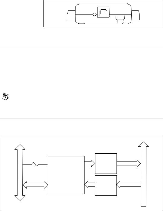
Figure 2. USB-6525 Back View
Installing Software
Software support for the USB-6525 for Windows 2000/XP is provided by
NI-DAQmx.
The NI-DAQmx CD contains example programs that you can use to get started programming with the USB-6525. Refer to the NI-DAQmx for USB Devices Getting Started Guide, that shipped with your device and is also accessible from Start»All Programs»National Instruments»NI-DAQ for more information.
Note For information about non-Windows operating system support, refer to ni.com/ info and enter rddqld.
Hardware
The block diagram in Figure 3 shows key functional components of the
USB-6525.
Full-Speed USBInterface |
Vbus |
P0 |
SSRs |
P0.<0..7>A/B |
Digital I/O TerminalBlock |
|
|
||||||
|
USB Microcontroller |
|
|
|||
|
|
Current- |
|
|||
USB |
P1 |
Limiting |
P1.<0..7>+/ |
|||
Isolated |
||||||
|
|
|
||||
|
|
Inputs |
|
Figure 3. USB-6525 Block Diagram
USB-6525 User Guide and Specifications |
2 |
ni.com |

Refer to the Safety Guidelines section of this document for important safety information.
Setting Up Hardware
Complete the following steps to set up the hardware:
1.Install combicon screw terminal blocks by inserting them into the combicon jacks.
Note The USB-6525 kit ships with signal labels. You can apply the signal labels on the screw terminal blocks for easy signal identification.
2.Refer to Table 1 and Figure 4 for label orientation and affix provided signal labels to the screw terminal blocks. Insert the screw terminal blocks into their respective matching combicon jacks. Refer to Figure 4 for more information about signal label orientation.
3 |
4 |
1 |
|
2 |
|
3 |
|
4 |
|
1 |
Overlay Label with Pin Orientation Guides |
3 |
Screw Terminal Blocks |
2 |
Combicon Jack |
4 |
Signal Labels |
Figure 4. Signal Label Application Diagram
3.Connect the wiring to the appropriate screw terminals.
© National Instruments Corporation |
3 |
USB-6525 User Guide and Specifications |
I/O Connector
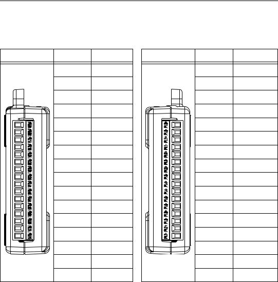
The USB-6525 device ships with two detachable terminal blocks for digital signals. Each individual terminal accepts a wire gauge between
16 AWG–28 AWG.
Table 1. Digital Terminal Assignments
Module |
Terminal |
Signal |
|
1 |
P0.0A |
|
2 |
P0.0B |
|
3 |
P0.1A |
|
4 |
P0.1B |
|
5 |
P0.2A |
|
6 |
P0.2B |
|
7 |
P0.3A |
|
8 |
P0.3B |
|
9 |
P0.4A |
|
10 |
P0.4B |
|
11 |
P0.5A |
|
12 |
P0.5B |
|
13 |
P0.6A |
|
14 |
P0.6B |
|
15 |
P0.7A |
|
16 |
P0.7B |
Module |
Terminal |
Signal |
|
17 |
P1.0+ |
|
18 |
P1.0– |
|
19 |
P1.1+ |
|
20 |
P1.1– |
|
21 |
P1.2+ |
|
22 |
P1.2– |
|
23 |
P1.3+ |
|
24 |
P1.3– |
|
25 |
P1.4+ |
|
26 |
P1.4– |
|
27 |
P1.5+ |
|
28 |
P1.5– |
|
29 |
P1.6+ |
|
30 |
P1.6– |
|
31 |
P1.7+/PFI 0+ |
|
32 |
P1.7–/PFI 0– |
USB-6525 User Guide and Specifications |
4 |
ni.com |

Signal Descriptions
Table 2 describes the signals available on the I/O connectors.
Table 2. Signal Descriptions
Signal Name |
Direction |
Description |
|
|
|
|
|
|
P0.<0..7>A/B |
Output |
Solid-state relay 60 VDC/30 Vrms (42.4 Vpk) output |
|
|
|
P1.<0..6>+/– |
Input |
±60 VDC digital input. |
|
|
P1.<0..6>+ corresponds to the positive input terminal. |
|
|
P1.<0..6>– corresponds to the negative input terminal. |
|
|
|
P1.7+/– or PFI 0+/– |
Input |
This channel is configurable as either a digital input or |
|
|
an event counter. |
|
|
Digital Input Signal—±60 VDC digital input. |
|
|
P1.7+ corresponds to the positive input terminal. |
|
|
P1.7– corresponds to the negative input terminal. |
|
|
CTR—As a counter, this signal can be used as an event |
|
|
counter input source. |
|
|
PFI 0+ corresponds to the positive counter terminal. |
|
|
PFI 0– corresponds to the negative counter terminal. |
|
|
|
Digital I/O
USB-6525 has eight channel-to-channel optically isolated inputs, P1.<0..7>, and eight channel-to-channel optically isolated solid-state relay outputs, P0.<0..7>. P1.7/PFI 0 can also function as a 32-bit counter. Refer to the Event Counter section for more information about the counter.
Optically Isolated Inputs
The USB-6525 provides eight channels of isolated digital inputs. These inputs consist of an optocoupler, a depletion-mode MOSFET-based current-limiting circuit, and Schottky diode.
Each channel has its own positive and negative terminals. The input range on the channels is –60 VDC to +60 VDC.
Sensing DC Voltages
The USB-6525 detects a wide range of DC signals, from TTL-like logic levels to DC power supply levels up to 60 V.
© National Instruments Corporation |
5 |
USB-6525 User Guide and Specifications |
Loading...