


PXI
NI PXI-8108 User Manual
September 2008 372561B-01
Worldwide Technical Support and Product Information
ni.com
National Instruments Corporate Headquarters
11500 North Mopac Expressway Austin, Texas 78759-3504 USA Tel: 512 683 0100
Worldwide Offices
Australia 1800 300 800, Austria 43 662 457990-0, Belgium 32 (0) 2 757 0020, Brazil 55 11 3262 3599, Canada 800 433 3488, China 86 21 5050 9800, Czech Republic 420 224 235 774, Denmark 45 45 76 26 00, Finland 358 (0) 9 725 72511, France 01 57 66 24 24, Germany 49 89 7413130, India 91 80 41190000, Israel 972 3 6393737, Italy 39 02 41309277, Japan 0120-527196, Korea 82 02 3451 3400,
Lebanon 961 (0) 1 33 28 28, Malaysia 1800 887710, Mexico 01 800 010 0793, Netherlands 31 (0) 348 433 466, New Zealand 0800 553 322, Norway 47 (0) 66 90 76 60, Poland 48 22 3390150, Portugal 351 210 311 210, Russia 7 495 783 6851, Singapore 1800 226 5886, Slovenia 386 3 425 42 00, South Africa 27 0 11 805 8197, Spain 34 91 640 0085, Sweden 46 (0) 8 587 895 00, Switzerland 41 56 2005151, Taiwan 886 02 2377 2222, Thailand 662 278 6777, Turkey 90 212 279 3031, United Kingdom 44 (0) 1635 523545
For further support information, refer to the Technical Support and Professional Services appendix. To comment on National Instruments documentation, refer to the National Instruments Web site at ni.com/info and enter the info code feedback.
© 2008 National Instruments Corporation. All rights reserved.

Important Information
Warranty
The NI PXI-8108 is warranted against defects in materials and workmanship for a period of one year from the date of shipment, as evidenced by receipts or other documentation. National Instruments will, at its option, repair or replace equipment that proves to be defective during the warranty period. This warranty includes parts and labor.
The media on which you receive National Instruments software are warranted not to fail to execute programming instructions, due to defects in materials and workmanship, for a period of 90 days from date of shipment, as evidenced by receipts or other documentation. National Instruments will, at its option, repair or replace software media that do not execute programming instructions if National Instruments receives notice of such defects during the warranty period. National Instruments does not warrant that the operation of the software shall be uninterrupted or error free.
A Return Material Authorization (RMA) number must be obtained from the factory and clearly marked on the outside of the package before any equipment will be accepted for warranty work. National Instruments will pay the shipping costs of returning to the owner parts which are covered by warranty.
National Instruments believes that the information in this document is accurate. The document has been carefully reviewed for technical accuracy. In the event that technical or typographical errors exist, National Instruments reserves the right to make changes to subsequent editions of this document without prior notice to holders of this edition. The reader should consult National Instruments if errors are suspected. In no event shall National Instruments be liable for any damages arising out of or related to this document or the information contained in it.
EXCEPT AS SPECIFIED HEREIN, NATIONAL INSTRUMENTS MAKES NO WARRANTIES, EXPRESS OR IMPLIED, AND SPECIFICALLY DISCLAIMS ANY WARRANTY OF MERCHANTABILITY OR FITNESS FOR A PARTICULAR PURPOSE. CUSTOMER’S RIGHT TO RECOVER DAMAGES CAUSED BY FAULT OR NEGLIGENCE ON THE PART OF NATIONAL
INSTRUMENTS SHALL BE LIMITED TO THE AMOUNT THERETOFORE PAID BY THE CUSTOMER. NATIONAL INSTRUMENTS WILL NOT BE LIABLE FOR DAMAGES RESULTING FROM LOSS OF DATA, PROFITS, USE OF PRODUCTS, OR INCIDENTAL OR CONSEQUENTIAL DAMAGES, EVEN IF ADVISED OF THE POSSIBILITY THEREOF. This limitation of
the liability of National Instruments will apply regardless of the form of action, whether in contract or tort, including negligence. Any action against National Instruments must be brought within one year after the cause of action accrues. National Instruments shall not be liable for any delay in performance due to causes beyond its reasonable control. The warranty provided herein does not cover damages, defects, malfunctions, or service failures caused by owner’s failure to follow the National Instruments installation, operation, or maintenance instructions; owner’s modification of the product; owner’s abuse, misuse, or negligent acts; and power failure or surges, fire, flood, accident, actions of third parties, or other events outside reasonable control.
Copyright
Under the copyright laws, this publication may not be reproduced or transmitted in any form, electronic or mechanical, including photocopying, recording, storing in an information retrieval system, or translating, in whole or in part, without the prior written consent of National Instruments Corporation.
National Instruments respects the intellectual property of others, and we ask our users to do the same. NI software is protected by copyright and other intellectual property laws. Where NI software may be used to reproduce software or other materials belonging to others, you may use NI software only to reproduce materials that you may reproduce in accordance with the terms of any applicable license or other legal restriction.
Trademarks
National Instruments, NI, ni.com, and LabVIEW are trademarks of National Instruments Corporation. Refer to the Terms of Use section on ni.com/legal for more information about National Instruments trademarks.
The ExpressCard™ word mark and logos are owned by PCMCIA and any use of such marks by National Instruments is under license. Other product and company names mentioned herein are trademarks or trade names of their respective companies.
Members of the National Instruments Alliance Partner Program are business entities independent from National Instruments and have no agency, partnership, or joint-venture relationship with National Instruments.
Patents
For patents covering National Instruments products/technology, refer to the appropriate location: Help»Patents in your software, the patents.txt file on your media, or the National Instruments Patent Notice at ni.com/patents.
WARNING REGARDING USE OF NATIONAL INSTRUMENTS PRODUCTS
(1)NATIONAL INSTRUMENTS PRODUCTS ARE NOT DESIGNED WITH COMPONENTS AND TESTING FOR A LEVEL OF RELIABILITY SUITABLE FOR USE IN OR IN CONNECTION WITH SURGICAL IMPLANTS OR AS CRITICAL COMPONENTS IN ANY LIFE SUPPORT SYSTEMS WHOSE FAILURE TO PERFORM CAN REASONABLY BE EXPECTED TO CAUSE SIGNIFICANT INJURY TO A HUMAN.
(2)IN ANY APPLICATION, INCLUDING THE ABOVE, RELIABILITY OF OPERATION OF THE SOFTWARE PRODUCTS CAN BE IMPAIRED BY ADVERSE FACTORS, INCLUDING BUT NOT LIMITED TO FLUCTUATIONS IN ELECTRICAL POWER SUPPLY, COMPUTER HARDWARE MALFUNCTIONS, COMPUTER OPERATING SYSTEM SOFTWARE FITNESS, FITNESS OF COMPILERS AND DEVELOPMENT SOFTWARE USED TO DEVELOP AN APPLICATION, INSTALLATION ERRORS, SOFTWARE AND HARDWARE COMPATIBILITY PROBLEMS, MALFUNCTIONS OR FAILURES OF ELECTRONIC MONITORING OR CONTROL DEVICES, TRANSIENT FAILURES OF ELECTRONIC SYSTEMS (HARDWARE AND/OR SOFTWARE), UNANTICIPATED USES OR MISUSES, OR ERRORS ON THE PART OF THE USER OR APPLICATIONS DESIGNER (ADVERSE FACTORS SUCH AS THESE ARE HEREAFTER COLLECTIVELY TERMED “SYSTEM FAILURES”). ANY APPLICATION WHERE A SYSTEM FAILURE WOULD CREATE A RISK OF HARM TO PROPERTY OR PERSONS (INCLUDING THE RISK OF BODILY INJURY AND DEATH) SHOULD NOT BE RELIANT SOLELY UPON ONE FORM OF ELECTRONIC SYSTEM DUE TO THE RISK OF SYSTEM FAILURE. TO AVOID DAMAGE, INJURY, OR DEATH, THE USER OR APPLICATION DESIGNER MUST TAKE REASONABLY PRUDENT STEPS TO PROTECT AGAINST SYSTEM FAILURES, INCLUDING BUT NOT LIMITED TO BACK-UP OR SHUT DOWN MECHANISMS. BECAUSE EACH END-USER SYSTEM IS CUSTOMIZED AND DIFFERS FROM NATIONAL INSTRUMENTS' TESTING PLATFORMS AND BECAUSE A USER OR APPLICATION DESIGNER MAY USE NATIONAL INSTRUMENTS PRODUCTS IN COMBINATION WITH OTHER PRODUCTS IN A MANNER NOT EVALUATED OR CONTEMPLATED BY NATIONAL INSTRUMENTS, THE USER OR APPLICATION DESIGNER IS ULTIMATELY RESPONSIBLE FOR VERIFYING AND VALIDATING THE SUITABILITY OF NATIONAL INSTRUMENTS PRODUCTS WHENEVER NATIONAL INSTRUMENTS PRODUCTS ARE INCORPORATED IN A SYSTEM OR APPLICATION, INCLUDING, WITHOUT LIMITATION, THE APPROPRIATE DESIGN, PROCESS AND SAFETY LEVEL OF SUCH SYSTEM OR APPLICATION.

Contents
About This Manual
How to Use the Documentation Set............................................................................... |
ix |
Conventions ................................................................................................................... |
ix |
Related Documentation.................................................................................................. |
x |
Chapter 1
Introduction
Benefits of PXI .............................................................................................................. |
1-1 |
NI PXI-8108 .................................................................................................................. |
1-2 |
Description ...................................................................................................... |
1-2 |
Functional Overview ....................................................................................... |
1-2 |
NI PXI-8108 Functional Description................................................ |
1-2 |
National Instruments Software ...................................................................................... |
1-4 |
Chapter 2
Installation and Configuration
Installing the NI PXI-8108 ............................................................................................ |
2-1 |
How to Remove the Controller from the PXI Chassis .................................... |
2-4 |
BIOS Setup .................................................................................................................... |
2-5 |
Accessing BIOS Setup Utility ......................................................................... |
2-5 |
Main Setup Menu ............................................................................................ |
2-6 |
Advanced Setup Menu .................................................................................... |
2-6 |
SATA Configuration Submenu......................................................... |
2-7 |
CPU Configuration Submenu ........................................................... |
2-8 |
Video Configuration Submenu ......................................................... |
2-8 |
ExpressCard Configuration Submenu............................................... |
2-9 |
USB Configuration Submenu ........................................................... |
2-9 |
Serial/Parallel Port Configuration Submenu..................................... |
2-10 |
Serial Port 0 Configuration Submenu................................. |
2-10 |
Parallel Port Configuration Submenu................................. |
2-10 |
Trigger Router Configuration Submenu ........................................... |
2-11 |
LabVIEW RT Options Setup Menu ................................................................ |
2-11 |
Boot Setup Menu............................................................................................. |
2-12 |
Boot Settings Configuration Submenu ............................................. |
2-13 |
Hard Drive BBS Priorities Submenu ................................................ |
2-13 |
CD/DVD ROM Drive BBS Priorities Submenu............................... |
2-13 |
Floppy Drive BBS Priorities Submenu............................................. |
2-14 |
Network Device BBS Priorities Submenu ........................................ |
2-14 |
© National Instruments Corporation |
v |
NI PXI-8108 User Manual |
Contents
Security Menu ................................................................................................. |
2-14 |
Save & Exit Menu........................................................................................... |
2-14 |
System CMOS ............................................................................................................... |
2-15 |
LabVIEW RT Installation ............................................................................................. |
2-17 |
LabVIEW RT Software Installation ............................................................... |
2-17 |
LabVIEW RT Configuration Switches ........................................................... |
2-19 |
Drivers and Software..................................................................................................... |
2-21 |
Files and Directories Installed on Your Hard Drive ....................................... |
2-21 |
PXI Features .................................................................................................................. |
2-21 |
PXI Trigger Connectivity................................................................................ |
2-21 |
Chassis Configuration ................................................................................................... |
2-22 |
Basic PXI System Configuration .................................................................... |
2-22 |
Upgrading RAM............................................................................................................ |
2-23 |
Hard Drive Recovery..................................................................................................... |
2-24 |
Installing an OS ............................................................................................................. |
2-25 |
Installing from a CD-ROM ............................................................................. |
2-25 |
ExpressCard................................................................................................................... |
2-25 |
Installing an ExpressCard ............................................................................... |
2-25 |
Removing an ExpressCard.............................................................................. |
2-26 |
Chapter 3
I/O Information
Front Panel Connectors ................................................................................................. |
3-1 |
Front Panel..................................................................................................................... |
3-2 |
DVI-I............................................................................................................... |
3-3 |
COM1.............................................................................................................. |
3-5 |
Ethernet ........................................................................................................... |
3-6 |
Parallel Port..................................................................................................... |
3-7 |
Universal Serial Bus........................................................................................ |
3-9 |
Trigger............................................................................................................. |
3-10 |
GPIB (IEEE 488.2) ......................................................................................... |
3-11 |
ExpressCard/34 Slot........................................................................................ |
3-12 |
Front Panel Features ...................................................................................................... |
3-14 |
Data Storage .................................................................................................................. |
3-14 |
Chapter 4
Common Configuration Questions
General Questions ......................................................................................................... |
4-1 |
Boot Options.................................................................................................................. |
4-1 |
Cables and Connections ................................................................................................ |
4-2 |
Software Driver Installation .......................................................................................... |
4-3 |
Upgrade Information ..................................................................................................... |
4-4 |
PXI Configuration ......................................................................................................... |
4-6 |
NI PXI-8108 User Manual |
vi |
ni.com |
Contents
Chapter 5
Troubleshooting
Appendix A
Specifications
Appendix B
Technical Support and Professional Services
Glossary
Index
© National Instruments Corporation |
vii |
NI PXI-8108 User Manual |

About This Manual
This manual contains detailed instructions for installing and configuring your National Instruments PXI-8108 embedded controller kit.
How to Use the Documentation Set
|
|
Begin by reading the NI PXI-8108 Installation Guide, a brief quick-start |
|
|
guide that describes how to install and get started with your controller. |
|
|
This manual, the NI PXI-8108 User Manual, contains more details about |
|
|
changing the installation or configuration from the defaults and using the |
|
|
hardware. |
Conventions |
|
|
|
|
|
|
|
The following conventions appear in this manual: |
» |
|
The » symbol leads you through nested menu items and dialog box options |
|
|
to a final action. The sequence File»Page Setup»Options directs you to |
|
|
pull down the File menu, select the Page Setup item, and select Options |
|
|
from the last dialog box. |
|
|
This icon denotes a tip, which alerts you to advisory information. |
|
|
|
|
|
|
|
|
This icon denotes a note, which alerts you to important information. |
|
|
This icon denotes a caution, which advises you of precautions to take to |
|
|
avoid injury, data loss, or a system crash. |
bold |
Bold text denotes items that you must select or click in the software, such |
|
|
|
as menu items and dialog box options. Bold text also denotes parameter |
|
|
names. |
italic |
Italic text denotes variables, emphasis, a cross-reference, or an introduction |
|
|
|
to a key concept. Italic text also denotes text that is a placeholder for a word |
|
|
or value that you must supply. |
© National Instruments Corporation |
ix |
NI PXI-8108 User Manual |

About This Manual
monospace |
Text in this font denotes text or characters that you should enter from the |
|
keyboard, sections of code, programming examples, and syntax examples. |
|
This font is also used for the proper names of disk drives, paths, directories, |
|
programs, subprograms, subroutines, device names, functions, operations, |
|
variables, filenames, and extensions. |
monospace bold |
Bold text in this font denotes the messages and responses that the computer |
|
automatically prints to the screen. This font also emphasizes lines of code |
|
that are different from the other examples. |
Related Documentation
The following documents contain information you may find helpful as you read this manual:
•PICMG 2.0 R3.0 CompactPCI Specification, PCI Industrial Computers Manufacturers Group
•IEEE Standard P1284.1-1997 (C/MM) Standard for Information Technology for Transport Independent Printer/System Interface
•PCI Local Bus Specification, Revision 2.3, PCI Special Interest Group
•PXI Hardware Specification, Revision 2.2, PXI Systems Alliance
•PXI Software Specification, Revision 2.1, PXI Systems Alliance
•Serialized IRQ Support for PCI Systems Specification, Revision 6.0, Compaq Computer et al.
•ExpressCard Standard, Release 1.0, PCMCIA
•Universal Serial Bus (USB) Specification, Revision 2.0
•Digital Visual Interface (DVI) Specification, Revision 1.0
•IEEE Std 488.1-2003, IEEE Standard for Higher Performance Protocol for the Standard Digital Interface for Programmable Instrumentation
NI PXI-8108 User Manual |
x |
ni.com |

1
Introduction
Benefits of PXI
The PXI (PCI eXtensions for Instrumentation) industry standard, an open specification governed by the PXI Systems Alliance (PXISA), defines a compact modular PC platform for test, measurement, and control systems. Since PXI leverages the PCI bus, PXI users receive all the benefits of PCI within an architecture that supports mechanical, electrical, and software features tailored to industrial instrumentation, data acquisition, industrial automation, and control applications.
Well-suited for industrial applications, PXI leverages from the CompactPCI specification, which defines a rugged form factor for PCI that offers superior mechanical integrity and easy installation and removal of hardware components. PXI products offer higher and more carefully defined levels of environmental performance required by the vibration, shock, temperature, and humidity extremes of industrial environments. PXI adds mandatory environmental testing and active cooling to the CompactPCI mechanical specification to ease system integration and ensure multivendor interoperability.
Additionally, PXI meets the more specific needs of instrumentation users by adding an integrated trigger bus and reference clock for multiple-board synchronization, a star trigger bus for very precise timing, and local buses for side-band communication between adjacent peripherals.
© National Instruments Corporation |
1-1 |
NI PXI-8108 User Manual |

Chapter 1 |
Introduction |
NI PXI-8108
Description
The NI PXI-8108 PXI/CompactPCI embedded computer is a high-performance PXI/CompactPCI system controller. The NI PXI-8108 controller integrates standard I/O features in a single unit by using state-of-the-art packaging. Combining an NI PXI-8108 embedded controller with a PXI-compatible chassis, such as the NI PXI-1042, results in a fully PC-compatible computer in a compact, rugged package.
The NI PXI-8108 has an Intel® Core™ 2 Duo processor T9400 (2.53 GHz dual core processor), all the standard I/O, and a 80 GB (or larger) hard drive. It also has a PCI-based GPIB controller and an ExpressCard/34 expansion slot.
The standard I/O on each module includes DVI-I (Digital Video Interface Integrated Analog/Digital) video, one RS-232 serial port, a parallel port, four Hi-Speed USB ports, Gigabit Ethernet, a reset button, and a PXI trigger.
Functional Overview
This section contains functional descriptions of each major logic block on the NI PXI-8108 embedded computer.
NI PXI-8108 Functional Description
The NI PXI-8108 is a modular PC in a PXI 3U-size form factor. Figure 1-1 is a functional block diagram of the NI PXI-8108. Following the diagram is a description of each logic block shown.
NI PXI-8108 User Manual |
1-2 |
ni.com |
|
|
|
|
|
|
Chapter 1 |
Introduction |
|
|
|
Socket 479 |
|
|
|
|
|
|
|
|
CPU |
|
|
|
|
|
|
|
|
Chipset |
PCIe |
PCIe-to-PCI |
PCI |
GPIB |
|
|
|
|
|
|
|
||||
SO-DIMM |
Single CH |
Graphics |
|
Bridge |
|
|
|
|
|
|
|
|
|
||||
DDR2 SDRAM |
|
Memory |
|
|
|
|
|
|
PC2-6400 |
|
Controller |
|
DVI-I |
|
|
|
|
|
|
Hub |
|
|
|
|
|
|
|
|
|
Connector |
|
|
|
|
|
|
Gigabit |
|
|
|
|
|
|
|
|
Ethernet |
DMI |
|
|
|
|
|
|
Flash ROM |
|
|
|
|
|
|
|
|
|
|
Chipset |
|
|
|
PXI |
|
|
4 Hi-Speed |
|
|
|
Connector |
|
|
||
|
I/O |
PCI Bus |
|
|
|
|
||
USB |
|
|
|
|
|
|||
|
Controller |
|
|
|
|
|||
Connectors |
|
|
|
|
PXI |
|
|
|
|
Hub |
|
|
|
|
|
||
|
|
|
|
|
|
|
||
|
|
|
|
|
|
Trigger |
|
|
SATA |
|
|
|
|
|
|
|
|
ExpressCard/34 |
|
LPC Bus |
|
|
|
|
|
|
Slot |
|
|
|
|
|
|
|
|
|
|
|
|
|
|
SMB to |
|
|
|
LPT 1 |
|
|
|
PXI Trigger |
|
|
|
|
|
|
|
|
|
|
|
|
|
|
Super I/O |
|
|
|
Watchdog |
|
|
|
COM 1 |
|
|
|
|
|
|
|
|
|
|
|
|
Timer |
|
|
|
|
|
|
|
|
|
SMB |
|
|
Figure 1-1. NI PXI-8108 Block Diagram
The NI PXI-8108 consists of the following logic blocks on the CPU module and the I/O module. The CPU module has the following logic blocks:
•Socket 479 CPU is the socket definition for the Intel® Core™ 2 Duo processor T9400.
•The SO-DIMM block consists of one 64-bit DDR2 SDRAM socket that can hold up to 4 GB.
© National Instruments Corporation |
1-3 |
NI PXI-8108 User Manual |

Chapter 1 |
Introduction |
•The Mobile Intel GM45 Express Chipset (Graphics and Memory Controller Hub) connects to the CPU, DDR2 SDRAM, DVI-I video, and GPIB.
•The SMB to PXI Trigger provides a routable connection of the PXI triggers to/from the SMB on the front panel.
•The Watchdog Timer block consists of a watchdog timer that can reset the controller or generate a trigger.
•The Chipset ICH9M (I/O Controller Hub) connects to the PCI, USB, SATA, LPC buses, and Ethernet.
•The USB Connectors are connected to the ICH9M chipset.
•The PXI Connector connects the NI PXI-8108 to the PXI/CompactPCI backplane.
•The Super I/O block represents the other peripherals supplied by the NI PXI-8108. The NI PXI-8108 has one serial port, and an ECP/EPP parallel port.
•The Gigabit Ethernet connects to either 10 Mbit, 100 Mbit, or 1,000 Mbit Ethernet interfaces.
•The GPIB block contains the GPIB interface.
•The ExpressCard/34 slot accommodates an ExpressCard/34 module.
•The SATA block connects a Serial ATA hard drive to the ICH9M.
National Instruments Software
National Instruments has developed several software tools you can use with the NI PXI-8108.
National Instruments’ hardware and software work together to help you make the most of your PXI system. The LabVIEW, Measurement Studio, and LabWindows™/CVI™ application development environments combine with leading hardware drivers such as NI-DAQmx to provide exceptional control of NI hardware. Instrument drivers are available at ni.com/idnet to simplify communication with instruments over a variety of busses.
LabVIEW is a powerful and easy-to-use graphical programming environment you can use to acquire data from thousands of different instruments including USB, IEEE 488.2, VXI, serial, PLCs, and plug-in boards. LabVIEW helps you convert acquired data into meaningful results using powerful data analysis routines. Add-on tools provide additional specialized functionality. For more information visit ni.com/labview and ni.com/toolkits.
NI PXI-8108 User Manual |
1-4 |
ni.com |
Chapter 1 |
Introduction |
If you prefer to use Microsoft’s Visual Basic, Visual C++, and
Visual Studio .NET for the core of your application, Measurement Studio adds tools for Measurement and Automation to each language. For more information visit ni.com/mstudio.
LabWindows/CVI is an interactive ANSI C programming environment designed for building virtual instrument applications. LabWindows/CVI delivers a drag-and-drop editor for building user interfaces, a complete ANSI C environment for building your test program logic, and a collection of automated code generation tools, as well as utilities for building automated test systems, monitoring applications, or laboratory experiments. For more information visit ni.com/lwcvi.
NI-DAQmx provides an extensive library of functions that you can call from your application development environment or interactive environment such as NI Signal Express. These functions provide an intuitive API for National Instruments’ multifunction DAQ products. Features available include analog input (A/D conversion), buffered data acquisition (high-speed A/D conversion), analog output (D/A conversion), waveform generation, digital I/O, counter/timer operations, SCXI signal conditioning, RTSI or PXI synchronization, self-calibration, messaging, and acquiring data to extended memory. For more information visit ni.com/daq.
National Instruments’ Modular Instruments use specialized drivers suited to each product’s specialization. Express VIs provide customized, interactive programming of instruments in a single interface and soft front panels provide an interface for testing the functionality of each instrument with no programming required. NI Switches, DMMs, High-Speed DIO, High-Speed Digitizers, and Sources each have customized drivers for high-end modular instrumentation systems. RF applications leverage two drivers, NI-RFSG and NI-RFSA and Dynamic Signal Acquisition is available through NI-DAQmx. For more information visit ni.com/ modularinstruments.
You can expand the timing and triggering functionality of your PXI system with PXI Timing and Synchronization products. These products provide precision clock sources, custom routing of triggers for multi-chassis synchronization, clock sharing, and more and are programmed with NI-Sync. For more information visit ni.com/pxi.
© National Instruments Corporation |
1-5 |
NI PXI-8108 User Manual |
Chapter 1 |
Introduction |
NI-VISA is the National Instruments implementation of the VISA specification. VISA is a uniform API for communicating and controlling USB, Serial, GPIB, PXI, VXI, and various other types of instruments. This API aids in the creation of portable applications and instrument drivers. For information on writing your own PXI instrument driver with NI-VISA, refer to the NI-VISA Getting Started Manual and the readme.txt file in the NI-VISA directory. For more information visit ni.com/visa.
With LabVIEW for Linux and support for over two hundred devices on Linux with the NI-DAQmx driver, you can now create Virtual Instruments based on the Linux OS. Instrument control in Linux has been improved by the NI-VISA driver for Linux and NI Modular Instruments are partially supported. For more information visit ni.com/linux.
NI PXI-8108 User Manual |
1-6 |
ni.com |

2
Installation and Configuration
This chapter contains information about installing and configuring your
NI PXI-8108 controller.
Installing the NI PXI-8108
This section contains general installation instructions for the NI PXI-8108. Consult your PXI chassis user manual for specific instructions and warnings.
1.Plug in your chassis before installing the NI PXI-8108. The power cord grounds the chassis and protects it from electrical damage while you install the module. (Make sure the power switch is turned off.)
Caution To protect both yourself and the chassis from electrical hazards, leave the chassis powered off until you finish installing the NI PXI-8108 module.
2.Remove any filler panels blocking access to the system controller slot (slot 1) in the chassis.
3.Touch the metal part of the case to discharge any static electricity that might be on your clothes or body.
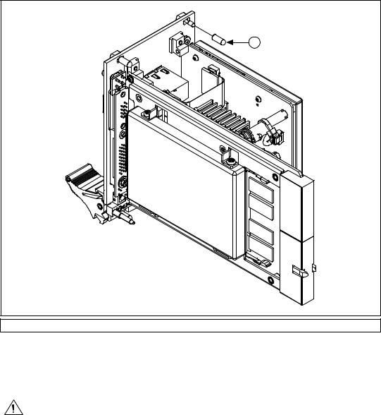
4.Remove the protective plastic covers from the four bracket-retaining screws as shown in Figure 2-1.
© National Instruments Corporation |
2-1 |
NI PXI-8108 User Manual |
Chapter 2 Installation and Configuration
1
1 Protective Screw Cap (4X)
Figure 2-1. Removing Protective Screw Caps
5.Make sure the injector/ejector handle is in its downward position. Align the NI PXI-8108 with the card guides on the top and bottom of the system controller slot.
Caution Do not raise the injector/ejector handle as you insert the NI PXI-8108. The module will not insert properly unless the handle is in its downward position so that it does not interfere with the injector rail on the chassis.
6.Hold the handle as you slowly slide the module into the chassis until the handle catches on the injector/ejector rail.
NI PXI-8108 User Manual |
2-2 |
ni.com |
Chapter 2 Installation and Configuration
7.Raise the injector/ejector handle until the module firmly seats into the backplane receptacle connectors. The front panel of the NI PXI-8108 should be even with the front panel of the chassis.
8.Tighten the four bracket-retaining screws on the top and bottom of the front panel to secure the NI PXI-8108 to the chassis.
9.Check the installation.
10.Connect the keyboard and mouse to the appropriate connectors. If you are using a PS/2 keyboard and a PS/2 mouse, a Y-splitter adapter is available to connect both to a single USB connector. Refer to
Figure 4-1, Y-Splitter Cable.
11.Connect the DVI monitor video cable to the DVI connector. If you are using a VGA monitor, use the DVI-to-VGA adapter included with your kit.
12.Connect devices to ports as required by your system configuration.
13.Power on the display device.
14.Power on the chassis.
15.Verify that the controller boots. If the controller does not boot, refer to the What if the NI PXI-8108 does not boot? section of Chapter 5, Troubleshooting.
© National Instruments Corporation |
2-3 |
NI PXI-8108 User Manual |

Chapter 2 Installation and Configuration
Figure 2-2 shows an NI PXI-8108 installed in the system controller slot of a National Instruments PXI-1042 chassis. You can place PXI devices in any other slots.
|
1 |
|
|
|
|
|
|
2 |
|
NI |
PXI- |
|
|
|
|
|
|
|
||
|
|
|
|
|
|
|
|
|
|
|
1042 |
|
|
|
|
3 |
|
|
|
|
1 |
PXI-1042 Chassis |
2 |
NI PXI-8108 Controller |
3 |
Injector/Ejector Rail |
|
Figure 2-2. NI PXI-8108 Controller Installed in a PXI Chassis
How to Remove the Controller from the PXI Chassis
The NI PXI-8108 controller is designed for easy handling. To remove the unit from the PXI chassis, complete the following steps:
1.Power off the chassis.
2.Remove any cables that may be attached to the controller front panel.
3.Unscrew the bracket-retaining screws in the front panel. Refer to Figure 2-1 for the location of these screws.
4.Press the injector/ejector handle down.
5.Slide the unit out of the chassis.
NI PXI-8108 User Manual |
2-4 |
ni.com |

Chapter 2 Installation and Configuration
BIOS Setup
You can change the NI PXI-8108 configuration settings in the BIOS setup program. The BIOS is the low-level interface between the hardware and operating system software that configures and tests your hardware when you boot the system. The BIOS setup program includes menus for configuring settings and enabling NI PXI-8108 controller features.
Most users do not need to use the BIOS setup program, as the NI PXI-8108 controller ships with default settings that work well for most configurations.
Caution Changing BIOS settings may lead to incorrect controller behavior and possibly an unbootable controller. If this happens, follow the instructions for restoring default settings in the System CMOS section. In general, do not change a setting unless you are absolutely certain what it does.
Accessing BIOS Setup Utility
Complete the following steps to start the BIOS setup program.
1.Power on or reboot your NI PXI-8108 controller.
2.When the message <DEL> = BIOS Setup Menu appears, press the <Del> key. The setup program loads after a short delay.
The Main menu is displayed when you first enter the BIOS setup program.
Use the following keys to navigate through the BIOS setup program:
•Left Arrow, Right Arrow—Use these keys to move between the different setup menus. If you are in a submenu, these keys have no effect, and you must press <Esc> to leave the submenu first. (To use the arrows on the numeric keypad, you must turn off Num Lock.)
•Up Arrow, Down Arrow—Use these keys to move between the options within a setup menu. (To use the arrows on the numeric keypad, you must turn off Num Lock.)
•<Enter>—Use this key either to enter a submenu or display all available settings for a highlighted configuration option.
•<Esc>—Use this key to return to the parent menu of a submenu.
At the top-level menus, this key serves as a shortcut to the Exit menu.
•<+> and <–>—Use these keys to cycle between all available settings for a selected configuration option.
© National Instruments Corporation |
2-5 |
NI PXI-8108 User Manual |

Chapter 2 Installation and Configuration
•<Tab>—Use this key to select time and date fields.
•<F9>—Use this key to load the optimal default values for BIOS configuration settings. The optimal default values are the same as the shipping configuration default values.
Main Setup Menu
The most commonly accessed and modified BIOS settings are in the Main setup menu. The Main setup menu reports the following configuration information:
•BIOS Version and Build Date—These values indicate the version of the PXI-8108 controller BIOS and the date on which the BIOS was built.
•Processor Type, Speed, and Number of Cores—These values indicate the type of processor used in the PXI-8108 controller, the speed of the processor, and the number of processor cores.
•System Memory—This value indicates the size of system RAM detected by the BIOS.
The Main setup menu also includes the following settings:
•System Time—This setting controls the time of day, which is stored in a battery-backed real-time clock. Most operating systems also include a way to change this setting. Use <+> and <–> in conjunction with <Enter> and <Tab> to change these values.
•System Date—This setting controls the date, which is stored in a battery-backed real-time clock. Most operating systems also include a way to change this setting. Use <+> and <–> in conjunction with <Enter> and <Tab> to change these values.
Advanced Setup Menu
This menu contains BIOS settings that normally do not require modification. If you have specific problems such as unbootable disks or resource conflicts, you may need to examine these settings.
Caution Changing settings in this menu may result in an unstable or unbootable controller. If this happens, follow the procedures outlined in the System CMOS section to restore BIOS settings to their factory defaults.
NI PXI-8108 User Manual |
2-6 |
ni.com |
Chapter 2 Installation and Configuration
The Advanced setup menu includes the following settings and submenus:
•SATA Configuration—Use this setting to access the SATA Configuration submenu. Refer to the SATA Configuration Submenu section for more information.
•CPU Configuration—Use this setting to access the CPU Configuration submenu. Refer to the CPU Configuration Submenu section for more information.
•Video Configuration—Use this setting to access the Video Configuration submenu. Refer to the Video Configuration Submenu section for more information.
•ExpressCard Configuration—Use this setting to access the
ExpressCard Configuration submenu. Refer to the ExpressCard Configuration Submenu section for more information.
•USB Configuration—Use this setting to access the USB Configuration submenu. Refer to the USB Configuration Submenu section for more information.
•Serial/Parallel Port Configuration—Use this setting to access the Serial/Parallel Port Configuration submenu. Refer to the
Serial/Parallel Port Configuration Submenu section for more information.
•Trigger Router Configuration—Use this setting to access the Trigger Router Configuration submenu. Refer to the Trigger Router Configuration Submenu section for more information.
SATA Configuration Submenu
Use this submenu to apply alternate settings to the hard disk drive (HDD) interfaces. Normally, you do not need to modify these settings, as the factory default settings provide the most compatible and optimal configuration possible.
•SATA Controller—This setting specifies whether or not the onboard SATA controller is enabled or disabled. The default value is Enabled.
–SATA Mode Selection—This setting determines whether AHCI mode is enabled or disabled for the SATA port. Some operating systems, such as Windows 2000, do not support AHCI mode. You can use this setting to disable AHCI mode so that non-compatible OSes function correctly. The default value is AHCI.
•Serial ATA Port 0—This item displays the onboard SATA drive detected in the system.
© National Instruments Corporation |
2-7 |
NI PXI-8108 User Manual |
Chapter 2 Installation and Configuration
CPU Configuration Submenu
Use this submenu to apply alternate settings to the CPU. Normally, you do not need to modify these settings, as the factory default settings provide the most compatible and optimal configuration possible.
•Core Multi-Processing Controller—This setting specifies whether or not the second core of the processor is enabled or disabled. The default value is Enabled.
•CPU Virtualization—This setting determines whether the Intel VT-x virtualization support is enabled or disabled. A virtual machine monitor (VMM) can utilize the additional hardware capabilities provided by the VT-x processor extensions. The default value is
Enabled.
•Processor Type, Speed, and Number of Cores—These values indicate the type of processor used in the NI PXI-8108 controller, the speed of the processor, and the number of processor cores.
Video Configuration Submenu
Use this submenu to apply alternate settings to the video configuration. Normally, you do not need to modify these settings, as the factory default settings provide the most compatible and optimal configuration possible.
•Primary Display—This setting specifies which video adapter the BIOS should use as the primary adapter if more than one is present. To use an external video adapter as the primary graphics adapter, choose
Add-in PCI Video. The default value is Onboard Video.
•Total Graphics Memory—This setting specifies the amount of system memory to allocate as graphics memory for use by the onboard video device. The default value is 256 MB.
•DDC Routing—This setting determines how the monitor DDC is routed. Use this setting to select whether or not the DDC is routed for an analog monitor or a DVI monitor. In order to use a DVI monitor, this setting must be set to DVI. An analog monitor, however, will function with this option set to either Analog or DVI. The DDC communication path is only enabled when set to Analog for an analog monitor, so certain advanced features of your analog monitor may only be enabled when routing DDC to Analog. The default setting is DVI.
NI PXI-8108 User Manual |
2-8 |
ni.com |

Chapter 2 Installation and Configuration
ExpressCard Configuration Submenu
Use this submenu to apply alternate settings to the ExpressCard configuration. These settings determine how much memory space, I/O space, and PCI bus numbers will be pre-allocated for the
ExpressCard port, allowing non-PCI Express-aware operating systems to support hot-plugging ExpressCard devices. Normally, you do not need to modify these settings, as the factory default settings provide the most compatible and optimal configuration possible.
•Reserved Buses—This setting determines the number of PCI buses that will be reserved by the BIOS for ExpressCard PCI-PCI bridges that may be hot-plugged in the ExpressCard slot. The default value for this setting is 8 PCI buses.
•Reserved Memory—This setting determines the amount of memory space, in bytes, that will be reserved by the BIOS for PCI-PCI bridges that may be hot-plugged in the ExpressCard slot. The default value for this setting is 32M bytes of memory.
•Reserved I/O—This setting determines the amount of I/O space, in bytes, that will be reserved by the BIOS for PCI-PCI bridges that may be hot-plugged in the ExpressCard slot. The default value for this setting is 4K bytes of I/O space.
USB Configuration Submenu
Use this submenu to apply alternate configurations to the USB ports. Normally, you do not need to modify these settings, as the factory default settings provide the most compatible and optimal configuration possible.
•USB Devices—This item lists the total number of devices detected in the system, categorized by device type.
•Legacy USB Support—This setting specifies whether or not legacy USB support is enabled. Legacy USB support refers to the ability to use a USB keyboard and mouse during system boot or in a legacy operating system such as DOS. The default value is Enabled.
Note Certain real-time applications may require you to disable this setting to reduce loop time jitter. When the controller is configured to boot LabVIEW RT, legacy USB support is automatically disabled.
•Device Reset Delay—This setting specifies the number of seconds the Power-On Self Test will wait for a USB mass storage device to start. The default is 20 seconds.
© National Instruments Corporation |
2-9 |
NI PXI-8108 User Manual |
Chapter 2 Installation and Configuration
In addition, the following option is available for each detected device if a
USB mass storage device is present:
•Emulation Type—This setting specifies how the BIOS will present the USB mass storage device to the system. This option can be used to present a USB mass storage device as a floppy, Zip, hard disk, or CD-ROM drive. The default is Auto, which allows the BIOS to treat small USB flash disk drives as floppy drives and larger USB flash disk drives as hard disk drives.
Serial/Parallel Port Configuration Submenu
Use this submenu to apply alternate configurations to the serial and parallel ports. Normally, you do not need to modify these settings, as the factory default settings provide the most compatible and optimal configuration possible.
•Serial Port 0 Configuration—Use this setting to access the Serial Port 0 Configuration submenu. Refer to the Serial Port 0 Configuration Submenu section for more information.
•Parallel Port Configuration—Use this setting to access the Parallel Port Configuration submenu. Refer to the Parallel Port Configuration Submenu section for more information.
Serial Port 0 Configuration Submenu
•Serial Port—This setting enables or disables the onboard serial port. The default value is Enabled.
•Device Settings—This item displays the current base address and interrupt request level (IRQ) information for the onboard serial port.
•Change Settings—This setting changes the base address and interrupt request level (IRQ) information for the onboard serial port. The default value is Auto.
Parallel Port Configuration Submenu
•Parallel Port—This setting enables or disables the onboard parallel port. The default value is Enabled.
•Device Settings—This item displays the current base address and interrupt request level (IRQ) information for the onboard parallel port.
•Device Mode—This settings enables alternate modes of operation for the parallel port. Usually the default setting works for all applications. The default is STD Printer Mode.
NI PXI-8108 User Manual |
2-10 |
ni.com |

Chapter 2 Installation and Configuration
•Change Settings—This setting changes the base address and interrupt request level (IRQ) information for the onboard parallel port. The default value is Auto. Note that the options available vary based upon the Device Mode selected for the parallel port.
Trigger Router Configuration Submenu
Use this submenu to program the front panel trigger router configuration. Normally, you do not need to modify these settings, as the factory default settings provide the most compatible and optimal configuration possible.
•Route Front Panel Trigger—This setting specifies how the front panel SMB trigger should be routed. The front panel trigger can be routed to System Reset, allowing an external trigger to reset the system. The default value is Disabled.
LabVIEW RT Options Setup Menu
Use this menu to configure boot options for LabVIEW RT if it is installed on the controller. If you are not using LabVIEW RT, you should leave these settings at default.
Note The settings below override the behavior of the switches on SW1. Refer to the LabVIEW RT Configuration Switches section for more information. To use the settings from the switches, select Use Switch Setting for each option.
•Boot Configuration—This setting selects whether the controller should boot LabVIEW RT, LabVIEW RT Safe Mode, or an installed OS such as Windows XP. The default is Use Switch Setting.
•Reset IP Address—If the controller is deployed to a different subnet from which it was originally configured, or if the current IP address is invalid, use this switch to reset the IP address to 0.0.0.0 during LabVIEW RT startup. The default is Use Switch Setting.
Note Once the Reset IP switch is unset, the target will automatically attempt to connect to the network using DHCP. If the target is unable to initiate a DHCP connection, the target connects to the network with a link-local IP address.
•Disable Startup VI—If the controller becomes inaccessible because of a startup VI, this switch can prevent VIs from automatically running at startup. The default is Use Switch Setting.
© National Instruments Corporation |
2-11 |
NI PXI-8108 User Manual |
 Loading...