


OPERATING INSTRUCTIONS AND SPECIFICATIONS
NI 9237
4-Channel, 24-Bit Half/Full-Bridge Analog Input Module
Français Deutsch
ni.com/manuals

This document describes how to use the National Instruments 9237 and includes specifications and pin assignments for the NI 9237. Visit ni.com/info and enter rdsoftwareversion to determine which software you need for the modules you are using. For information about installing, configuring, and programming the system, refer to the system documentation. Visit ni.com/info and enter cseriesdoc for information about C Series documentation.
Note The safety guidelines and specifications in this document are specific to the NI 9237. The other components in the system might not meet the same safety ratings and specifications. Refer to the documentation for each component in the system to determine the safety ratings and specifications for the entire system. Visit ni.com/info and enter cseriesdoc for information about C Series documentation.
NI 9237 Operating Instructions and Specifications |
2 |
ni.com |
Safety Guidelines
Operate the NI 9237 only as described in these operating instructions.
Hot Surface This icon denotes that the component may be hot. Touching this component may result in bodily injury.
Safety Guidelines for Hazardous Locations
The NI 9237 is suitable for use in Class I, Division 2, Groups A, B, C, D, T4 hazardous locations; Class I, Zone 2, AEx nC IIC T4, and Ex nC IIC T4 hazardous locations; and nonhazardous locations only. Follow these guidelines if you are installing the NI 9237 in a potentially explosive environment. Not following these guidelines may result in serious injury or death.
Caution Do not disconnect I/O-side wires or connectors unless power has been switched off or the area is known to be nonhazardous.
Caution Do not remove modules unless power has been switched off or the area is known to be nonhazardous.
© National Instruments Corp. |
3 |
NI 9237 Operating Instructions and Specifications |

Caution Substitution of components may impair suitability for Class I, Division 2.
Caution For Zone 2 applications, install the system in an enclosure rated to at least IP 54 as defined by IEC 60529 and EN 60529.
Caution For Zone 2 applications, connected signals must be within the following limits:
Capacitance.......................... |
0.2 μF max |
Inductance............................ |
80 mH max |
Special Conditions for Hazardous Locations Use in Europe
This equipment has been evaluated as EEx nC IIC T4 equipment under DEMKO Certificate No. 03 ATEX 0324020X. Each module is marked  II 3G and is suitable for use in Zone 2 hazardous locations. If you are using the NI 9237 in Gas Group IIC hazardous locations or in ambient temperatures of –40 °C ≤ Ta ≤ 70 °C, you must use the device in an NI chassis that has been evaluated as EEx nC IIC T4, Ex nA IIC T4, or Ex nL IIC T4 equipment.
NI 9237 Operating Instructions and Specifications |
4 |
ni.com |

Special Conditions for Marine Applications
Some modules are Lloyd’s Register (LR) Type Approved for marine applications. To verify Lloyd’s Register certification, visit ni.com/certification and search for the LR certificate, or look for the Lloyd’s Register mark on the module.
Caution To meet radio frequency emission requirements for marine applications, use shielded cables and install the system in a metal enclosure. Suppression ferrites must be installed on power supply inputs near power entries to modules and controllers. Power supply and module cables must be separated on opposite sides of the enclosure and must enter and exit through opposing enclosure walls.
© National Instruments Corp. |
5 |
NI 9237 Operating Instructions and Specifications |
Connecting the NI 9237
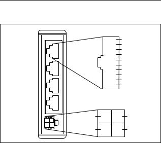
The NI 9237 has four RJ-50 receptacles that provide connections for four half or full bridges.
|
Ch0 – Ch3 |
|
|
|
1 |
SC |
|
|
2 |
AI+ |
|
Ch 0 |
3 |
AI– |
|
4 |
RS+ |
||
|
|||
|
5 |
RS– |
|
Ch 1 |
6 |
EX+ |
|
7 |
EX– |
||
|
|||
|
8 |
T+ |
|
|
9 |
T– |
|
Ch 2 |
10 |
SC |
Ch 3 |
|
EX+ |
EX+ |
EX– |
EX– |
Figure 1. NI 9237 Pin Assignments
NI 9237 Operating Instructions and Specifications |
6 |
ni.com |

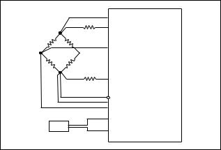
When you connect a half bridge to the NI 9237, you must connect the AI+, EX–, and RS– signals, but you do not connect the AI– signal. When you connect a full bridge, you must connect the AI+, AI–, EX–, and RS– signals. Refer to Figure 2 for an illustration of how to connect half and full bridges to the NI 9237.
Note You can use a quarter bridge with the NI 9237 if you add a resistor externally to create a half bridge. You also can use a quarter bridge with the NI 9237 if you use the NI 9944 or NI 9945 Quarter Bridge Completion Accessory. Visit ni.com and search for the NI 9944 and NI 9945 Quarter Bridge Completion Accessories for more information about these accessories and how to purchase them.
Note National Instruments does not recommend using an RJ-45 cable with the NI 9237 because it can physically damage pins 1 and 10 on the device, and thus permanently disable shunt calibration no matter what connector you use.
© National Instruments Corp. |
7 |
NI 9237 Operating Instructions and Specifications |

The NI 9237 has a four-terminal external excitation voltage source connector. You can use the EX+ and EX– terminals on the connector to connect one external excitation voltage source to the module. You can use the additional EX+ and EX– terminals on the connector to wire multiple NI 9237 modules together in a daisy chain.
Note When you insert or remove a new sensor from the NI 9237, slight changes in the excitation voltages can cause a mismatch between the internal half-bridge completion resistors and the half-bridge sensors, which results in a change in the measurement offsets. National Instruments recommends performing bridge calibrations of quarteror half-bridge sensors after connecting all sensors to the NI 9237 and after removing or attaching any additional sensor. Visit ni.com/info and enter the info code rdw9237 for more information about changes in voltage offsets in the NI 9237.
NI 9237 Operating Instructions and Specifications |
8 |
ni.com |
 RS+
RS+
 EX+
EX+
 AI+
AI+

 AI–
AI–
 EX–
EX–
RS–
 SC
SC
 SC
SC
 T+
T+
TEDS
 T–
T–
NI 9237
Figure 2. Connecting a Half or Full Bridge to the NI 9237
© National Instruments Corp. |
9 |
NI 9237 Operating Instructions and Specifications |
Each channel on the NI 9237 has an independent 24-bit ADC and an input amplifier that enable you to sample signals from all four channels simultaneously.
The NI 9237 is isolated from earth ground. However, the individual channels are not isolated from each other. The EX+, EX–, and T– signals are common among all channels. You can connect the NI 9237 to a device that is biased at any voltage within the NI 9237 rejection range of earth ground. Refer to the Specifications section for more information about the common-mode rejection
ratio (CMRR).
You also can connect floating signals to the NI 9237. If you connect floating signals to the NI 9237, National Instruments recommends connecting the EX– signal to the earth ground or shield for better noise rejection.
The NI 9237 also includes filters to prevent aliasing. The filters on the NI 9237 filter according to the data rate. Refer to the
Understanding NI 9237 Filtering section for more information about filtering.
NI 9237 Operating Instructions and Specifications 10 |
ni.com |
Wiring TEDS Channels
Ensure that neither the TEDS data (T+) nor the TEDS return (T–) signal is tied in common to any AI signals on the NI 9237. The NI 9237 connects all the T– signals together internally. Visit ni.com/info and enter the info code rdteds for more information about TEDS sensors.
NI 9237 Connection Options
Wiring resistance can create errors in bridge circuits. The NI 9237 provides two mechanisms to correct for these errors: remote sensing and shunt calibration.
Remote Sensing
Remote sensing continuously and automatically corrects for errors in excitation leads, and generally is most appropriate for halfand full-bridge sensors.
Long wire and small gauge wire have greater resistance, which can result in gain error. The resistance in the wires that connect the excitation voltage to the bridge causes a voltage drop, which is a source of gain error. The NI 9237 includes remote sensing to compensate for this gain error. Connect remote sense wires to the points where the excitation voltage wires connect to the bridge
© National Instruments Corp. |
11 |
NI 9237 Operating Instructions and Specifications |
 Loading...