


 ® L 54
DVD Receiver
Owner’s Manual Manuel d’Installation Bedienungsanleitung Gebruikershandleiding Manual del Usuario Manuale delle Istruzioni
Инструкция по эксплуатации Bruksanvisning
ENGLISH
FRANÇAIS
ESPAÑOL NEDERLANDS DEUTSCH
ITALIANO
РУССКИЙ
SVENSKA
ENGLISH
FRANÇAIS
ESPAÑOL NEDERLANDS DEUTSCH
ITALIANO
РУССКИЙ
SVENSKA
IMPORTANT SAFETY INSTRUCTIONS
Save these instructions for later use.
Follow all warnings and instructions marked on the audio equipment.
1Read instructions - All the safety and operating instructions should be read before the product is operated.
2Retain instructions - The safety and operating instructions should be retained for future reference.
3Heed Warnings - All warnings on the product and in the operating instructions should be adhered to.
4Follow Instructions - All operating and use instructions should be followed.
5Cleaning - Unplug this product from the wall outlet before cleaning. Do not use liquid cleaners or aerosol cleaners. Use a damp cloth for cleaning.
6Attachments - Do not use attachments not recommended by the product manufacturer as they may cause hazards.
7Water and Moisture - Do not use this product near water-for example, near a bath tub, wash bowl, kitchen sink, or laundry tub; in a wet basement; or near a swimming pool; and the like.
8Accessories - Do not place this product on an unstable cart, stand, tripod, bracket, or table. The product may fall, causing serious injury to a child or adult, and serious damage to the product. Use only with a cart, stand, tripod, bracket, or table recommended by the manufacturer, or sold with the product. Any mounting of the product should follow the manufacturer’s instructions, and should use a mounting accessory recommended by the manufacturer.
9 |
|
A product and cart combination should be moved with |
|
|
care. Quick stops, excessive force, and uneven surfaces may |
|
|
cause the product and cart combination to overturn. |
|
|
10Ventilation - Slots and openings in the cabinet are provided for ventilation and to ensure reliable operation of the product and to protect it from overheating, and these openings must not be blocked or covered. The openings should never be blocked by placing the product on a bed, sofa, rug, or other similar surface. This product should not be placed in a built-in installation such as a bookcase or rack unless proper ventilation is provided or the manufacturer’s instructions have been adhered to.
11Power Sources - This product should be operated only from the type of power source indicated on the marking label. If you are not sure of the type of power supply to your home, consult your product dealer or local power company.
The primary method of isolating the amplifier from the mains supply is to disconnect the mains plug. Ensure that the mains plug remains accessible at all times. Unplug the AC power cord from the AC outlet if the unit will not be used for several months or more.
12Grounding or Polarization - This product may be equipped with a polarized alternating-current line plug (a plug having one blade wider than the other). This plug will fit into the power outlet only one way. This is a safety feature. If you are unable to insert the plug fully into the outlet, try reversing the plug. If the plug should still fail to fit, contact your electrician to replace your obsolete outlet. Do not defeat the safety purpose of the polarized plug.
13Power - Cord Protection - Power-supply cords should be routed so that they are not likely to be walked on or pinched by items placed upon or against them, paying particular attention to cords at plugs, convenience receptacles, and the point where they exit from the product.
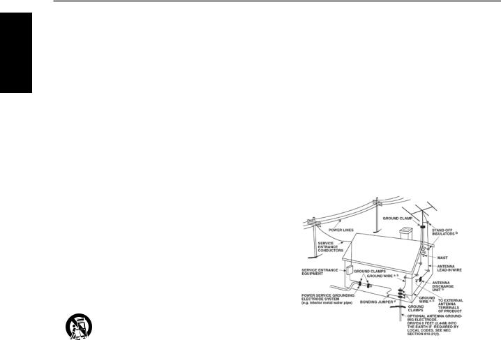
14Outdoor Antenna Grounding - If an outside antenna or cable system is connected to the product, be sure the antenna or cable system is grounded so as to provide some protection against voltage surges and built-up static charges. Article 810 of the National Electrical Code, ANSI/NFPA 70, provides information with regard to proper grounding of the mast and supporting structure, grounding of the lead-in wire
to an antenna discharge unit, size of grounding conductors, location of antenna discharge unit, connection to grounding electrodes, and requirements for the grounding electrode.
NOTE TO CATv SYSTEM INSTALLER
This reminder is provided to call the CATV system installer’s attention to Section 820-40 of the NEC which provides guidelines for proper grounding and, in particular, specifies that the cable ground shall be connected to the grounding system of the building, as close to the point of cable entry as practical.
15Lightning - For added protection for this product during a lightning storm, or when it is left unattended and unused for long periods of time, unplug it from the wall outlet and disconnect the antenna or cable system. This will prevent damage to the product due to lightning and power-line surges.
16Power Lines - An outside antenna system should not be located in the vicinity of overhead power lines or other electric light or power circuits, or where it can fall into such power lines or circuits. When installing an outside antenna system, extreme care should be taken to keep from touching such power lines or circuits as contact with them might be fatal.
17Overloading - Do not overload wall outlets, extension cords, or integral convenience receptacles as this can result in a risk of fire or electric shock.
18Object and Liquid Entry - Never push objects of any kind into this product through openings as they may touch dangerous voltage points or short-out parts that could result in a fire or electric shock. Never spill liquid of any kind on the product.
WARNING: The apparatus should noT be exposed to dripping or splashing, and objects filled with liquids, such as vases, should not be placed on the apparatus. As with any electronic products, use care not to spill liquids into any part of the system. Liquids can cause a failure and/or a fire hazard.
IMPORTANT SAFETY INSTRUCTIONS
19Damage Requiring Service - Unplug this product from the wall outlet and refer servicing to qualified service personnel under the following conditions:
a)When the power-supply cord or plug is damaged.
b)If liquid has been spilled, or objects have fallen into the product.
c)If the product has been exposed to rain or water.
d)If the product does not operate normally by following the operating instructions. Adjust only those controls that are covered by the operating instructions as an improper adjustment of other controls may result in damage and will often require extensive work by a qualified technician to restore the product to its normal operation.
e)If the product has been dropped or damaged in any way.
f)when the product exhibits a distinct change in performance-this indicates a need for service.
20Replacement Parts - When replacement parts are required, be sure the service technician has used replacement parts specified by the manufacturer or have the same characteristics as the original part. Unauthorized substitutions may result in fire, electric shock, or other hazards.
21Safety Check - Upon completion of any service or repairs to this product, ask the service technician to perform safety checks to determine that the product is in proper operating condition.
22Wall or Ceiling Mounting - The product should be mounted to a wall or ceiling only as recommended by the manufacturer.
23Heat - The product should be situated away from heat sources such as radiators, heat registers, stoves or other products (including amplifiers) that produce heat.
WARNING
TO REDUCE THE RISK OF FIRE OR ELECTRIC SHOCK, DO NOT EXPOSE THIS PRODUCT TO RAIN OR MOISTURE.
CAUTION
TO PREVENT ELECTRIC SHOCK, MATCH WIDE BLADE OF PLUG TO WIDE SLOT, FULLY INSERT.
CAUTION
This DVD Receiver employs a Laser System. To ensure proper use of this product, please read this owner’s manual carefully and retain for future reference. Should the unit require maintenance, contact an authorized service location. Use of controls, adjustments or the performance of procedures other than those specified may result in exposure to laser radiation. To prevent direct exposure to laser beam, do not try to open the enclosure. Visible laser radiation when the enclosure is opened.
DO NOT STARe INTO BEAM.
FCC NOTICE
This equipment has been tested and found to comply with the limits for a Class B digital device, pursuant to part 15 of the FCC Rules. These limits are designed to provide reasonable protection against harmful interference in a residential installation.
This equipment generates, uses and can radiate radio frequency energy and if not installed and used in accordance with the instructions, may cause harmful interference to radio communications. However, there is no guarantee that interference will not occur in a particular installation. If this equipment does cause harmful interference to radio or television reception, which can be determined by turning the equipment off and on, the user is encouraged to try to correct the interference by one or more of the following measures
•Reorient or relocate the receiving antenna.
•Increase the separation between the equipment and receiver.
•Connect the equipment into an outlet on a circuit different from that to which the receiver is connected
•Consult the dealer or an experienced radio/TV technician for help.
FCC WARNIng
Changes or modifications not expressly approved by the party responsible for compliance could void the user’s authority to operate the equipment.
INDUSTRY CAnada REQUIREMENT
This Class B digital apparatus meets all requirements of the Canadian Interference-Causing Equipment Regulations.
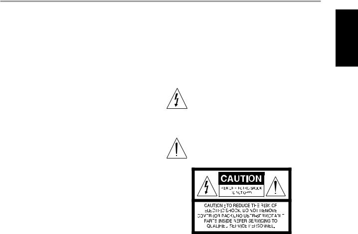
THE LIGHTNING FLASH WITH ARROWHEAD SYMBOL, WITHIN AN EQUILATERAL TRIANGLE, IS INTENDED TO ALERT THE USER TO THE PRESENCE OF UNINSULATED “DANGEROUS VOLTAGE” WITHIN THE PRODUCT’S ENCLOSURE THAT MAYBE OF SUFFICIENT MAGNITUDE TO CONSTITUTE A RISK OF ELECTRIC SHOCK TO PERSONS.
THE EXCLAMATION POINT WITHIN AN EQUILATERAL TRIANGLE IS INTENDED TO ALERT THE USER TO THE PRESENCE OF IMPORTANT OPERATING AND MAINTENANCE (SERVICING) INSTRUCTIONS IN THE LITERATURE ACCOMPANYING THE APPLIANCE.
The equipment draws its nominal non-operational power from the AC outlet with its POWER switch in the STANDBY position.
The socket-outlet shall be installed near the apparatus and shall be easily accessible.
CAUTION
Changes or modifications to this equipment not expressly approved by NAD Electronics for compliance could void the user’s authority to operate this equipment.
CAUTION Regarding PLACEMENT
To maintain proper ventilation, be sure to leave a space around the unit (from the largest outer dimensions including projections) that is equal to or greater than shown below.
Left and Right Panels: 10 cm Rear Panel: 10 cm
Top Panel: 50 cm
ENGLISH
FRANÇAIS
ESPAÑOL NEDERLANDS DEUTSCH
ITALIANO
РУССКИЙ
SVENSKA

ENGLISH
FRANÇAIS
ESPAÑOL NEDERLANDS DEUTSCH
ITALIANO
РУССКИЙ
SVENSKA
IMPORTANT SAFETY INSTRUCTIONS
IMPORTANT INFORMATION FOR UK CUSTOMERS
DO NOT cut off the mains plug from this equipment. If the plug fitted is not suitable for the power points in your home or the cable is too short to reach a power point, then obtain an appropriate safety approved extension lead or consult your dealer. If, nonetheless, the mains plug is cut off, REMOVE THE FUSE and dispose of the PLUG immediately, to avoid possible shock hazard by inadvertent connection to the mains supply. If this product is not provided with a mains plug, or one has to be fitted, then follow the instructions given below:
IMPORTANT
DO NOT make any connection to the larger terminal which is marked with the letter ‘E’ or by the safety earth symbol or colored GREEN or GREEN AND YELLOW.
The wires in the mains lead on this product are colored in accordance with the following code:
BLUE – NEUTRAL
BROWN – LIVE
As these colors may not correspond with the colored markings identifying the terminals in your plug, proceed as follows:
The BLUE wire must be connected to the terminal marked with the letter ‘N’ or colored BLACK.
The BROWN wire must be connected to the terminal marked with the letter ‘L’ or colored RED.
When replacing the fuse, only a correctly rated and approved type should be used, and be sure to re-fit the fuse cover.
IF IN DOUBT ConSULT A COMPETENT ELECTRICIAN.
NOTES ON ENVIRONMENTAL PROTECTION
At the end of its useful life, this product must not be disposed of with regular household waste but must be returned to a collection point for the recycling of electrical and electronic equipment. The symbol on the product, user’s manual and packaging, point this out.
The materials can be reused in accordance with their markings. Through re-use, recycling of raw materials or other forms of recycling of old products, you are making an important contribution to the protection of our environment. Your local administrative office can advise you of the responsible waste disposal point.
NOTE: The L 54 is not an auto voltage DVD Receiver. Connect only to the prescribed AC outlet, i.e., 120V 60Hz or 230V 50Hz.
This product incorporates copyright protection technology that is protected by method claims of certain U.S. patents and other intellectual property rights owned by Macrovision Corporation and other rights owners. Use of this copyright protection technology must be authorized by Macrovision Corporation, and is intended for home and other limited viewing uses only unless otherwise authorized by Macrovision Corporation. Reverse engineering or disassembly is prohibited.
Manufactured under License from Dolby Laboratories. “Dolby” and the double-D symbol are trademarks of Dolby Laboratories.
“DTS” and “DTS Digital Out” are registered trademarks of DTS, Inc.
RECORD YOur MODEL NUMBER (NOW, WHILE YOU CAN SEE IT)
The model and serial number of your new L 54 are located on the back of the cabinet. For your future convenience, we suggest that you record these numbers here:
Model no: __________________________
Serial no.: __________________________
NAD is a trademark of NAD Electronics International, a division of Lenbrook Industries Limited Copyright 2007, NAD Electronics International, a division of Lenbrook Industries Limited

Introduction
TABLE OF CONTENTS
IMPORTANT SAFETY INSTRUCTIONS............................... |
2 |
Introduction
GETTING THE MOST FROM THE L 54 . . . . . . . . . . . . . . . . 6
UNPACKING AND SETUP. . . . . . . . . . . . . . . . . . 6 QUICK START. . . . . . . . . . . . . . . . . . . . . . . . . . . . . . . . . . . . . . . . . . . . . . . . . . . . . . . . . .6 ABOUT THE L 54. . . . . . . . . . . . . . . . . . . . . . . . . . . . . . . . . . . . . . . . . . . . . . . . . . . .7 EASE OF USE. . . . . . . . . . . . . . . . . . 7 ABOUT THE HTR 4 SYSTEM REMOTE CONTROL . . . . . . . . . . . . .7
Identification of Controls
FRONT PANEL. . . . . . . . . . . . . . . . . . 8 REAR PANEL. . . . . . . . . . . . . . . . . . 10
Setup
SETTING UP THE L 54 . . . . . . . . . . . . . . . . . . 12
DEALING WITH HUM AND NOISE. . . . . . . . . . . . . . . . . . 12 FACTORY DEFAULT SETTINGS. . . . . . . . . . . . . . . . . . 12 ABOUT THE ON-SCREEN DISPLAY (OSD). . . . . . . . . . . . . . . 13 DISPLAYING THE L 54 DVD OSD. . . . . . . . . . . . . . . . . . . . . . . . . . . . . . . . . . . . 13 AUDIO MODE. . . . . . . . . . . . . . . . . . 13 INPUT SELECT. . . . . . . . . . . . . . . . . . 14 ADJUSTING THE VOLUME . . . . . . . . . . . . . . . . . . 14 ADJUSTING THE SUBWOOFER LEVEL TRIM “ON THE FLY”. . . . . . . . 14
Operation |
|
|
|
USING THE L 54. . . . . . . . . . . . . . |
. |
. . . 15 |
|
REGION MANAGEMENT INFORMATION. . |
. . |
. . . . . . . . |
. . . . 15 |
ABOUT DVD/SVCD/VCD/CD. . . . . . . . |
. . |
. . . . . . . . |
15 |
USING THE L 54’S INTERNAL DVD PLAYER – SETUP MENU. . |
. . . .16 |
||
OSD NAVIGATION. . . . . . . . . . . . . |
. . |
. . . 16 |
|
SETUP MENU . . . . . . . . . . . . . . . |
. . |
. 16 |
|
TV ASPECT RATIO. . . . . . . . . . . . . |
. . |
. . . 16 |
|
TV SYSTEM. . . . . . . . . . . . . . . . |
. . |
16 |
|
LANGUAGE. . . . . . . . . . . . . . . . |
. . |
17 |
|
SUBTITLE. . . . . . . . . . . . . . . . . . . . . . . . . . . . . . . . . |
. . . . |
. . . . . . . . . . . . . . . . |
. . . . . . . 17 |
DOWN SAMPLING. . . . . . . . . . . . . |
. . |
. . . 17 |
|
DIGITAL OUTPUT. . . . . . . . . . . . . . |
. . |
. . 17 |
|
PARENTAL LOCK (North America version only). |
. . . . . . . . |
. . . 17 |
|
P-SCAN. . . . . . . . . . . . . . . . . . |
18 |
||
SCREEN SAVER. . . . . . . . . . . . . . . |
. . |
. 18 |
|
VIDEO OUT . . . . . . . . . . . . . . . . |
. . |
18 |
|
DIVX CODE . . . . . . . . . . . . . . . . |
. . |
18 |
|
THANK YOU FOR CHOOSING NAD
The L 54 DVD Receiver is a technologically advanced and highly capable product-yet we have invested great effort in making it simple and easy to use. The L 54 delivers a range of genuinely useful options for stereo listening using powerful digital signal processing and superbly accurate digital-audio circuitry. However, we have also been careful to ensure that the L 54 is as musically transparent and spatially accurate as possible, incorporating much of what we’ve learned from a quarter-century’s
experience designing audio and home-theatre components. As with all our products, NAD’s “Music First” design philosophy guided the L 54’s design, such that it can confidently promise you both state-of-the-art surround home-theatre and audiophile-quality music listening for years to come.
USING THE L 54’S INTERNAL DVD PLAYER – FEATURES. . . . . . . 19
TITLE AND MENU BUTTONS. . . . . . . . . . . . . . . . . . 19 RANDOM PLAY . . . . . . . . . . . . . . . . . . 19 REPEAT. . . . . . . . . . . . . . . . . . 19 REPEAT A-B. . . . . . . . . . . . . . . . . . 19 SLOW. . . . . . . . . . . . . . . . . . 19 STILL PICTURE AND FRAME-BY-FRAME PLAYBACK . . . . . . . . . . 19 ZOOM. . . . . . . . . . . . . . . . . . 19 PROGRAMMING . . . . . . . . . . . . . . . . . . 20 PLAYING MP3/WMA/JPEG. . . . . . . . . . . . . . . . . . 20
USING THE L 54’s AM/FM RADIO.. . . . . . . . . . . . . . . . . . . . . . . . . . . . . . . . . .21
ABOUT ANTENNAS. . . . . . . . . . . . . . . . . . 21 ASSEMBLING THE LOOP ANTENNA. . . . . . . . . . . . . . . . . . 21 SELECTING THE RADIO. . . . . . . . . . . . . . . . . . 21 SETTING RADIO PRESET. . . . . . . . . . . . . . . . . . 21 DELETING A STORED PRESET. . . . . . . . . . . . . . . . . . 22 CHOOSING FM MUTE/MODE. . . . . . . . . . . . . . . . . . 22 ABOUT RDS. . . . . . . . . . . . . . . . . . 22 VIEWING RDS TEXT. . . . . . . . . . . . . . . . . . 22
USING THE HTR 4 REMOTE CONTROL . . . . . . . . . . . . . . . 23
SPECIFICATIONS . . . . . . . . . . . . . . . . . . 23 CONTROLLING THE L 54. . . . . . . . . . . . . . . . . . . . . . . . . . . . . . . . . . . . . . . . . . . . . 23 LEARNING CODES FROM OTHER REMOTES. . . . . . . . . . . . . . 24 PUNCH-THROUGH. . . . . . . . . . . . . . . . . . 24 COPY COMMAND FROM ANOTHER BUTTON. . . . . . . . . . . . . 24 MACRO COMMANDS . . . . . . . . . . . . . . . . . . 25 RECORDING MACROS. . . . . . . . . . . . . . . . . . 25 BUTTON ILLUMINATION TIMEOUT. . . . . . . . . . . . . . . . . . 26 FACTORY RESET. . . . . . . . . . . . . . . . . . 26 DELETE MODE. . . . . . . . . . . . . . . . . . 26 LOADING CODE LIBRARIES. . . . . . . . . . . . . . . . . . 27 SEARCH MODE . . . . . . . . . . . . . . . . . . 27 CHECKING CODE-LIBRARY NUMBER. . . . . . . . . . . . . . . . . 28
Reference
TROUBLESHOOTING. . . . . . . . . . . . . . . . . . 29 SPECIFICATIONS. . . . . . . . . . . . . . . . . . 30 NOTES. . . . . . . . . . . . . . . . . . 31
We encourage you to take a few minutes now to read right through this manual. Investing a little time here at the outset might save you a good deal of time later, and is by far the best way to ensure that you make the most of your investment in the L 54, and get the most from this powerful and flexible home-theatre component.
One more thing: We urge you to register your L 54 ownership on the NAD Worldwide Web site:
http://NADelectronics.com/warranty
For warranty information contact your local distributor.
ENGLISH
FRANÇAIS
ESPAÑOL NEDERLANDS DEUTSCH
ITALIANO
РУССКИЙ
SVENSKA

ENGLISH
FRANÇAIS
ESPAÑOL NEDERLANDS DEUTSCH
ITALIANO
РУССКИЙ
SVENSKA
Introduction
GETTING THE MOST FROM THE L 54
UNPACKING AND SETUP
WHAT’S IN THE BOX
Packed with your L 54 you will find:
•An AM loop antenna
•An FM ribbon-wire antenna with balun
•The HTR 4 remote control with 4 (four) AAA batteries
•This owner’s manual
SAVE THe PACKAging
Please save the box and all of the packaging in which your L 54 arrived. Should you move or otherwise need to transport your L 54, this is by far the safest container in which to do so. We’ve seen too
many otherwise perfect components damaged in transit for lack of a proper shipping carton, so please: Save that box!
CHOOSING A Location
Choose a location that is well ventilated (with at least several inches to both sides and behind), and that will provide a clear line of sight, within 25 feet/8 meters, between the L 54’s front panel and your primary listening/viewing position. This will ensure reliable infrared remote control communications. The L 54 generates a modest amount of heat, but nothing that should trouble adjacent components. It is perfectly possible to stack the L 54 atop other components, but the reverse usually should be avoided.
Nonetheless, it is generally preferable that the L 54 stands alone. It is especially important that
sufficient ventilation be provided. If you are contemplating on locating the L 54 within a cabinet or other furniture, consult your NAD audio/video specialist for advice on providing adequate airflow.
QUICK START
In case you simply cannot wait to experience the performance of your new NAD L 54 DVD Receiver, we provide the following “Quick Start” instructions to get you underway. Before the steps below, connect your L 54 to a TV/monitor.
Please make all the connections to your L 54 with the unit unplugged. It is also advisable to powerdown or unplug all associated components while making or breaking any signal or AC power connections.
PLAY A Cd OR DVD MOvie
•Connect the L 54’s composite Video or S-Video “MONITOR OUT” jack to your TV/monitor’s corresponding input.
•Connect your left and right front speakers to the L 54’s “L” and “R” outputs. Make sure to connect red to red (“+”) and black to black (“-”) with care to avoid stray wires or strands crossing between terminals. If your system includes a powered subwoofer, connect the L 54’s “SUBWOOFER PRE-OUT” jack to its line input.
•Plug the AC mains plug into the AC outlet; the LED on the front panel will be illuminated blue indicating the L 54 is in standby mode ready to accept commands from either the front panel power switch or the HTR 4 remote.
•To start playback of the DVD player; press “DVD” at the HTR 4 remote’s Device Selector section and then “OPEN/CLOSE” button.
•Insert the media and press [PLAY] button to start playback. You should hear stereo sound, and see an image on the TV/monitor. (If one or the other fails to appear, you may need to use either the L 54’s on-screen menu system to check assignment of audio and video inputs (See section on “Video Out” under the heading “Operation.”)
Enjoy the movie or music, but be sure to set aside time to read this manual thoroughly, and to set up, calibrate, and configure your L 54 carefully and completely.

Introduction
GETTING THE MOST FROM THE L 54
ABOUT THE L 54
Though the L 54 is among the most technically sophisticated integrated Stereo DVD receivers, we worked hard to make it one of the most musically transparent home-theatre components available as well - this is what we mean by NAD’s “Music First” design philosophy. Here are just a few examples:
•High-performance components used throughout the receiver’s analog audio circuits maximize quality from all sources.
•The L 54 incorporates a high quality DVD player with exceptional playability. The player has support for DVD video, VCD, SVCD with playback control (PBC), DivX, CD audio such as CD-RW as well as recorded MP3, copyright-protected WMA and JPEG files.
•Gold-surfaced connectors are employed throughout to ensure maximum signal integrity.
EASE OF USE
Despite the effort NAD has invested in the L 54’s sonic performance, we expended no less in making it powerfully easy to use. Its design is uniquely simple for so sophisticated a component, and the HTR 4 universal remote control is equally understandable, as are the L 54’s own front panel and on-screen displays (OSD).
ABOUT THE HTR 4 SYSTEM REMOTE CONTROL
Packed with your L 54 is the NAD HTR 4 remote control, a full-system remote especially designed for easy use and understanding. Be sure to read the section “Using the HTR 4 Remote Control” to familiarize yourself with the remote’s layout and operations before proceeding to setup your L 54.
Chances are you will want to use your HTR 4 as your primary way to command your entire A/V system. The HTR 4 can be employed to operate additional NAD or other-brand components such as a second DVD/CD player, television, satellite/HDTV tuner, VCR, or virtually anything else that operates via standard infrared remote control.
ENGLISH
FRANÇAIS
ESPAÑOL NEDERLANDS DEUTSCH
ITALIANO
РУССКИЙ
SVENSKA
Identification of Controls
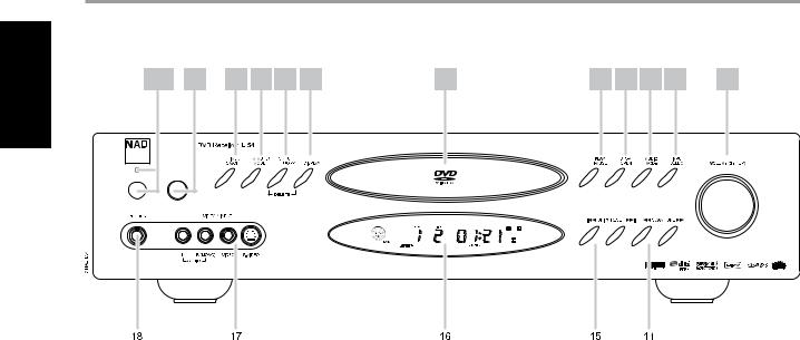
FRONT PANEL
ENGLISH |
1&2 |
3 |
4 |
5 |
6 |
7 |
8 |
9 |
10 |
11 |
12 |
13 |
|
||||||||||||
FRANÇAIS |
|
|
|
|
|
|
|
|
|
|
|
|
ESPAÑOL NEDERLANDS DEUTSCH
ITALIANO
РУССКИЙ
SVENSKA
18 |
|
17 |
|
16 |
|
15 |
|
14 |
|
|
|
|
|
|
|
|
|
1POWER : When the L 54 is first plugged into the AC power, the L 54’s clock will light in the main Vacuum Fluorescent Display (VFD) display showing the time of day. Press to switch ON the L 54 from standby, changing the standby indicator from bright blue to dark and illuminating the VFD display. Pressing the power switch again turns the unit back to standby. It is usual (and perfectly acceptable) to leave the L 54 in standby mode in between normal viewing and listening sessions.
Pressing the “STOP/OPEN”button on the front-panel or the HTR 4 remote’s “ON”button will switch the receiver ON, making it operational. Press
the remote’s “OFF”button to return to standby. Note that when you do choose to switch off to standby using the front panel Power button, the L 54’s memory back-up system will store channel level, tuner preset, and other settings for several weeks while the unit is switched off.
2INDICATOR : When the L 54 is in standby, the LED will light bright blue and at the same time, the VFD in the L 54 will display the L 54’s internal clock. This indicator will extinguish itself when the power cable is unplugged from the AC supply.
3REMOTE SENSOR : Point the HTR 4 at the remote sensor and press the buttons. Do not expose the remote sensor of the L 54 to a strong light source such as direct sunlight or illumination. If you do so, you may not be able to operate the receiver with the remote control.
Distance: About 23 ft (7 m) from the front of the remote sensor Angle: About 30° in each direction of the front of the remote sensor
4TIMER ON/OFF : Press and hold to set the internal clock, ON/OFF timer and display of the clock’s time. A red “clock face” will appear in the fluorescent display when the timer is activated.
To set the internal clock, press and hold the “TIMER ON/OFF” button for more than 4 seconds. Use the “SETUP/MEMORY” button to toggle between the hours and minutes. Use the “SKIP/PRESET” buttons to change the hours and minutes. There are two timers, one for when the L 54 powers on – “ON TIME”; the other for when the unit powers off
– “OFF TIME”. Both timers are also programmed in the same way.
5FM MUTE/MODE : In the normal ‘Mute’ position, only the stations with a strong signal can be listened to, and the noise between stations is muted. Pressing the “FM MUTE/MODE” button allows distant (and potentially noisy) stations to be received (See also “Choosing FM MUTE/ MODE under the section “Using the L 54’s AM/FM Radio”).
6SETUP/MEMORY : Use to store tuned stations to the L 54’s 60 preset-memory locations (See “Listening to Radio”). When DVD mode is selected, use this button to go the Setup Menu as shown on the On Screen Display (OSD). (See also the section “Setting Radio Presets” under “Using the L 54’s AM/FM Radio”).
7DISPLAY : Use this multifunction button to toggle between RDS PS, RDS RT and station frequency in FM Tuner mode (See the section “Viewing RDS Text under “Using the L 54’s AM/FM Radio”). When in either CABLE/SAT or VCR mode, this “DISPLAY” button will toggle between Optical or Coaxial and analog inputs. You can assign either Optical or Analog input to VCR and either Coaxial or Analog input to CABLE/SAT. When in DVD mode, pressing “DISPLAY” will toggle between the two DVD display navigation menus as well.
8DISC TRAY : With the DISC TRAY open, insert a DVD, VCD, CD or other compatible media disc face down onto the tray.
If the disc is placed upside down and it is a single sided disc, ‘NO DISC’ appears on both the L 54’s VFD and the TV/Monitor screen.
9PLAY/PAUSE : Press this button to toggle between Play and Pause of a DVD, VCD, CD and other compatible media disc.
If the disc tray is open, press this button to automatically close the tray and start playback if a disc is loaded.
10STOP/OPEN : Press this button to open and close the disc tray and simultaneously select the internal DVD player. When in standby, this button will also power ON the L 54 and open the disc tray at the same time.
During DVD playback, press this button to stop and at the same time pause playback of disc -“PRESS PLAY TO CONTINUE” will be displayed in the OSD and
“RESUME” at the VFD. If you do not want to resume play, press "STOP/OPEN" a second time and playback will come to a complete STOP. Press a third time and the disc tray will open.
11AUDIO MODE : Depending on the selected input, mode and audio format, press to toggle through SRS, TREBLE, BASS, LEFT balance level, RIGHT balance level and Dynamic Range Control (DRC).
Use the“VOLUME (SETUP)” knob or HTR 4’s Volume keys to adjust the settings. (See also section about“Audio Mode” under“Setting up the L 54”).

Identification of Controls
FRONT PANEL
12INPUT SELECT : Use to select an audio/video input along with its assigned analog or digital inputs Toggle to select through: Internal DVD CABLE/SAT VCR VIDEO 4 Internal AM tuner Internal FM tuner then back to Internal DVD. (See also section about “Input Select” under “Setting up the L 54”).
13VOLUME (SETUP) : Turn clockwise to increase the volume setting; counter clockwise to lower it. The VFD shows the setting displayed as increments between -61 through to 17.
The VOLUME knob is also used to increment/decrement Bass/Treble level, LEFT/RIGHT balance, set DRC level and turn ON/OFF SRS.
14SCAN/TUNE : Pressing momentarily the or
or button will manually scan the AM or FM band. Press and hold
 or
or for more than 2 seconds to search up or down; the L 54’s tuner will stop at the next sufficiently strong signal it encounters. Note too that this function “wraps,” and will continue searching up or down from one end of the AM or FM band to the other.
Press or
or during disc playback. Press repeatedly to select the desired scanning speed.
15SKIP/PRESEt :At AM/FM mode, press to step up or down between stored radio presets; 30 FM and 30 AM station presets are available. Note that this function “wraps”: Pressing
 or
or 
 will step from Preset 30 to Preset 1, or vice versa. “Unused” presets are skipped over.
In DVD mode, press
 to skip forward or
 to skip backward a track or chapter. When setting up the Timer, use the
 or
or 
 buttons to change the hours and minutes.
16VFD : The Vacuum Fluorescent Display (VFD) provides visual information on all of the L 54’s important modes, settings and functions.
17VIDEO 4 INPUT : Use these convenience jacks for occasional sources such as a camcorder, tape player, video game console or any other analog audio and composite/S-Video video sources. Select the Video 4 input using the HTR 4 remote or through the front panel“INPUT SELECT” button.
If your source has a single audio out jack only or is marked ‘mono output’ , plug this into the L 54’s Video 4 ‘R (Mono)’ input. On the other hand, if your source has two output jacks indicative of stereo output, insert both jacks into the L 54’s corresponding Video 4 ‘L’ and ‘R (Mono)’ input to achieve stereo output as well.
18PHONES : Accepts stereo headphone using a standard 1/4-inch stereo phone plug (use a suitable adaptor for headphones equipped with a smaller plug). Plugging in headphones automatically mutes output from the speakers (but not from the AUDIO OUT jacks of the VCR at SRS OFF).
ENGLISH
FRANÇAIS
ESPAÑOL NEDERLANDS DEUTSCH
ITALIANO
РУССКИЙ
SVENSKA

ENGLISH
FRANÇAIS
Identification of Controls
REAR PANEL
1 |
2 |
3 |
4 |
5 |
6 |
7 |
8 |
9 |
10 |
ESPAÑOL NEDERLANDS DEUTSCH
ITALIANO
РУССКИЙ
SVENSKA
13 |
|
12 |
|
11 |
|
|
|
|
|
ATTENTION!
Please make all the connections to your L 54 with the unit unplugged. It is also advisable to power down or unplug all associated components while making or breaking any signal or AC power connections.
1SPEAKERS : Connect the left and right terminals to the corresponding loudspeakers. Each output’s “+” (red) terminal and “-” (black) terminal must be connected to the corresponding “+” and “-” terminals of the loudspeaker. Use extra care to ensure that no stray wires or strands cross between posts or terminals at either end.
NOTES
•Use stranded wire of at least 16-gauge (AWG); specialized speaker cable may be valuable (consult your NAD audio specialist). Connections to the L 54 can be made with banana-type plugs, or using bare wire, or pins, by loosening the terminal’s plastic nut, making a clean, neat connection, and re-tightening carefully (use the transverse hole through the post for barewire or pin connections). To minimize the danger of short-circuits, ensure that only 1/2-inch of exposed wire or pin is employed in connecting.
•This unit is designed to produce optimum sound quality when connected to speakers with impedances within the receiver’s operating range. Please check that speakers are rated to be 8 ohms minimum per speaker.
2FM ANTENNA : The supplied wire “dipole” FM antenna will connect to the FM connector using the supplied “balun” adaptor. It will usually work best when mounted on a vertical surface such as a wall, with arms fully outstretched forming a horizontal “T” perpendicular to the origin point of the signal. Experiment with placement and orientation to yield the clearest sound and lowest background noise.
In areas of difficult FM reception, an external FM antenna can yield dramatic gains in quality; consult your NAD audio specialist or a professional antenna installer.
3AM ANTENNA : The AM loop antenna supplied with the L 54 (or a suitable replacement) is required for AM reception. Open the clip
terminal lever; insert the wire making sure to match the color-coded (white and black) ends of the wire to that of the terminal and close the lever ensuring that the lever locks the wire in place. Testing different positions for the antenna may improve reception; vertical orientation will usually produce the best results. Antenna proximity to large metal objects (appliances, radiators) may impair reception, as will attempts to lengthen the wire to the loop.
Note
An external AM antenna can improve long distance reception substantially; consult your NAD audio specialist or a professional antenna installer. Do not connect anything other than a loop antenna to the AM ANTENNA terminal.
4CABLE/SAT & VCR : These comprise the L 54’s principal inputs. Connect S-Video, composite video, and analog stereo audio from source components such as HDTV/satellite tuners. VCR may be used with recording components such as videocassette or DVD-recorders. Connect the L 54’s VCR Audio/Video OUT to these components’ recordinput. (Make sure that SRS is set to OFF). Note that VCR may freely be used for play-only components, in which case their OUT jacks would remain unconnected.
5PRE-OUT SUBWoofer : Connect this output to a powered (“active”) subwoofer (or to a power amplifier channel driving a passive system).
6IR IN : This input is connected to the output of an IR (infrared) repeater (Xantech or similar) or the IR output of another component to allow control of the L 54 from a remote location. Ask your dealer or custom installer for further details.
10
 Loading...