


Installation and Operation Instructions for SELECTRONIC® TATTLETALE® Annunciator Model ST8
ST-94112N
Revised 07-04
Section 25
(00-02-0758)
Please read the following information before installing. A visual inspection of this product for damage during shipping is recommended before mounting. It is your responsibility to have a qualified person install this unit and make sure it conforms to NEC and local codes.
GENERAL INFORMATION
WARNING
BEFORE BEGINNING INSTALLATION OF THIS MURPHY PRODUCT
Disconnect all electrical power to the machine.
Make sure the machine cannot operate during installation.
Follow all safety warnings of the machine manufacturer.
Read and follow all installation instructions.
Certain danger to human safety and to equipment may occur if some equipment is stopped without pre-warning. It is recommended that monitored functions be limited to alarm-only or to alarm before shutdown.
Specifications
All specifications apply to both models unless indicated.
Power Input (Operating Voltage): 8–32 VAC, 8–40 VDC
Sensor Inputs: 8 sensor switches, normally open or normally closed dry contacts.
Number of Alarm Points: ST8: 8 first out shutdown/alarm.
Lockout Time Delay During Startup:
25 to 35 seconds (selectable for each sensor input).
|
|
|
|
|
|
|
|
|
|
|
|
|
|
|
|
|
|
|
|
|
|
|
|
|
|
|
|
ST8-F |
|
|
|
|
|
|
ST8-G |
|
|
||||||
|
|
|
|
|
|
5-11/16 in. |
|
|
|
|
|
2-3/16 in. |
|
|
|
|
|
2-7/8 in. |
|
|
|
|
|
|
|
|
|
|
|
|
|
|
|
|
|
|
|
(73 mm) |
|
|
|
||
|
|
|
|
|
|
|
|
|
|
|
|
|
|||||||||
|
|
|
|
|
|
(144 mm) |
|
|
|
(56 mm) |
|
|
|
|
Clearance |
|
|
||||
|
|
|
|
|
|
|
|
|
|
|
|
|
|
|
|
|
|
|
|
|
|
|
|
|
|
|
|
|
|
|
|
|
|
|
|
|
|
|
|
|
|
|
|
|
|
|
|
|
|
|
|
|
|
|
|
|
|
|
|
|
|
|
|
|
|
|
|
|
|
|
|
|
|
|
|
|
|
|
|
|
|
|
|
|
|
|
|
6-3/8 in.
(162 mm)
5-7/8 in.
(149 mm)
|
|
|
|
|
|
|
|
|
|
|
|
|
Gimbal |
||||||||
|
|
|
|
|
|
|
|
|
|
|
|
|
Mounting |
||||||||
|
|
|
|
|
|
|
|
|
5-3/8 in. |
|
|
|
Bracket |
|
1-3/4 in. |
|
|
|
|
||
|
|
|
|
|
|
|
|
|
|
|
|
|
|
|
|
|
|||||
|
|
|
|
|
|
|
|
|
|
|
|
|
|
||||||||
|
|
|
|
|
|
|
|
|
|
|
|
|
|
|
|
|
|
|
|
||
|
|
|
|
|
|
|
|
|
|||||||||||||
|
|
|
|
|
|
|
|
|
(137 mm) |
|
|
|
|
|
(44 mm) |
|
|
|
|
||
|
|
|
|
|
|
|
|||||||||||||||
|
|
|
|
|
|
|
|
|
|
|
|
|
|
|
|
|
|
|
|
|
|
ST-94112N page 1 of 4
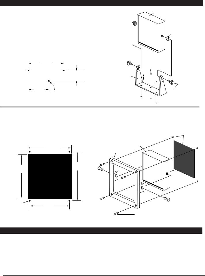
MOUNTING
Gimbal Mount Model (ST8-G)
1.Install the gimbal mounting bracket with three screws (customer supplied) according to the mounting hole dimensions shown below. NOTE: Verify the TATTLETALE®s rotation clearance (see Dimensions, page 1).
2.Attach the TATTLETALE® to the gimbal bracket with the washer and mounting bracket knobs.
TATTLETALE®
Washers (2)
Gimbal Mounting Bracket Hole Dimensions
3-1/2 in. |
Customer Supplied |
Bracket Mounting |
|
(89 mm) |
Screws (3) |
|
1 in. |
Gimbal |
|
(25 mm) |
Bracket |
1-3/4 in. |
|
Mounting Bracket |
(44 mm) |
9/64 in. (4 mm) |
Knobs (2) |
|
diameter 3 places |
|
Panel Mount Model (ST8-F)
1.Cut a hole in the panel according to the mounting hole dimensions shown below.
2.Install the flush mount mounting bracket on the TATTLETALE®.
3.Insert the TATTLETALE® into the hole through the front of the panel.
4.Install the four 6-32 x 5/8 screws supplied.
Mounting Holes
Panel Mounting Hole Dimensions
TATTLETALE®
5-5/16 in. |
Flushmount |
(135 mm) |
Bracket |
5-3/8 in. |
5-3/4 in. |
(146 mm) |
|
(137 mm) |
|
5/32 in. |
4-11/16 in. |
Bracket Mounting |
|
(4 mm) |
(119 mm) |
||
Screws (2) |
|||
Typical |
|
4 places |
Mounting |
|
Screws (4) |
APPLYING PREPRINTED LABELS
Preprinted label are supplied with the TATTLETALE®. These labels are precut, pressure sensitive and when properly applied are permanent. To insure proper label application perform the following steps:
1. Be sure the TATTLETALE®s faceplate is clean and free of oil.
2.Peel one label at a time and position on the faceplate in the box which matches the input sensor position.
3.Before pressing down, be sure label is correctly placed.
4.Press firmly on the label, and leave untouched for
several hours.
ST-94112N page 2 of 4
 Loading...