


Operation and Parts Manual
 SERIES
MODEL MVH406DSZ/
MVH406DSCPAS
REVERSIBLE PLATE COMPACTOR
(ROBIN D1B40T92040 DIESEL ENGINE)
Revision #7 (02/28/14)
To find the latest revision of this publication, visit our website at: www.multiquip.com
THIS MANUAL MUST ACCOMPANY THE EQUIPMENT AT ALL TIMES.

pROPOSITION 65 WARNING
Diesel engine exhaust and some of
page 2 — mvh406dsz/dsCPAs pLATE COMPACTOR • operation and parts manual — rev. #7 (02/28/14)

NOTES
mvh406dsz/dsCPAs pLATE COMPACTOR • operation and parts manual — rev. #7 (02/28/14) — page 3

Table of Contents
MVH406DZ/DSCPAS
Reversible Plate Compactor
Proposition 65 Warning............................................ |
2 |
Table Of Contents.................................................... |
4 |
Parts Ordering Procedures...................................... |
5 |
Safety Information............................................... |
6-10 |
Specifications......................................................... |
11 |
Dimensions............................................................ |
12 |
General Nformation................................................ |
13 |
Components........................................................... |
14 |
Basic Engine.......................................................... |
15 |
Inspection.......................................................... |
16-17 |
Operation.......................................................... |
18-22 |
Maintenance...................................................... |
23-28 |
Troubleshooting (Compactor)................................. |
29 |
Troubleshooting (Engine).................................. |
30-31 |
Explanation of Code in Remarks Column.............. |
32 |
Suggested Spare Parts.......................................... |
33 |
Componet Drawings |
|
Nameplates And Decals.................................... |
34-35 |
Vibrating Plate Assembly.................................. |
36-37 |
Base And Engine Assembly.............................. |
38-39 |
Vibrator Assembly............................................. |
40-41 |
Control Handle Assembly.................................. |
42-45 |
Hand Pump Assembly....................................... |
46-47 |
Battery Assembly.............................................. |
48-49 |
Compaction Analyzing System Assembly............ |
50-51 |
Electric Device Assembly.................................. |
52-53 |
Robin D1B40T92040 Diesel Engine
Spare Parts Kit Assembly................................. |
54-55 |
Accessories Assembly...................................... |
56-57 |
Crankcase Assembly........................................ |
58-59 |
Crankshaft Assembly........................................ |
60-61 |
Camshaft Assembly.......................................... |
62-63 |
Piston Assembly................................................ |
64-65 |
Cylinder Head Assembly................................... |
66-67 |
Oil Pump And Gov Assembly............................ |
68-69 |
Timing Assembly............................................... |
70-73 |
Blower, Flywheel And Alternator Assembly....... |
74-75 |
Injection Equipment Assembly.......................... |
76-79 |
Recoil Starter Assembly.................................... |
80-81 |
Air Ducting (A) Assembly ................................. |
82-83 |
Air Ducting (B) Assembly ................................. |
84-85 |
Crankcase Breathing System Assembly ............ |
86-87 |
Fuel Tank Assembly .......................................... |
88-91 |
Air Filter Assembly............................................. |
92-93 |
Exhaust Slicencer Assembly .............................. |
94-95 |
Starter Regulator Assembly................................ |
96-97 |
Electric Equipment Wiring Assembly.................... |
98-99 |
Speed Control Assembly................................ |
100-101 |
Terms And Conditions Of Sale — Parts............... |
102 |
 NOTICE
Specifications and part numbers are subject to change without notice.
page 4 — mvh406dsz/dsCPAs pLATE COMPACTOR • operation and parts manual — rev. #7 (02/28/14)

www.multiquip.com
Parts Ordering Procedures
Ordering parts has never been easier!
Choose from three easy options:
Effective: January 1st, 2006
Best deal! Order via internet (dealers Only):
Order parts on-line using Multiquip’s SmartEquip website!
■View Parts Diagrams
■Order Parts
■Print Specifi cation Information
Goto www.multiquip.com and click on
Order  Parts to log in and save!
If you have an MQ Account, to obtain a Username and Password, E-mail us at: parts@multiquip. com.
To obtain an MQ Account, contact your
District Sales Manager for more information.
Use the internet and qualify for a 5% discount on Standard orders for all orders which include complete part numbers.*
Note: Discounts Are Subject To Change
|
|
|
|
Order via Fax (dealers Only): |
|
Fax your order in and qualify for a 2% discount |
|
|
|
|
|
|
|
|
|||
|
|
|
|
All customers are welcome to order parts via Fax. |
|
on Standard orders for all orders which include |
||
|
|
|
|
|
||||
|
|
|
|
domestic (us) Customers dial: |
|
complete part numbers.* |
||
|
|
|
|
1-800-6-PARTS-7 (800-672-7877) |
|
|
|
|
|
Note: Discounts Are Subject To Change |
|||||||
|
|
|
|
|
||||
|
|
|
|
|
|
|||
|
|
|
|
|
|
|
|
|
|
|
|
|
|
|
|
Order via phone: |
domestic (us) dealers Call: |
||||||||
|
|
|
|
|
|
|
||||||||||
|
|
|
|
|
|
|||||||||||
|
|
|
|
|
|
|
|
|
|
|
|
|
|
1-800-427-1244 |
|
|
|
|
|
|
|
|
|
|
|
|
|
|
|
|
|
|
|
|
|
|
|
|
|
|
|
|
|
|
|
|
|
|
|
|
|
|
|
non-dealer Customers: |
|
|
|
|
|
|
|
||||||
|
|
|
International Customers should contact |
|||||||||||||
|
|
|
Contact your local Multiquip Dealer for |
|||||||||||||
|
|
|
their local Multiquip Representatives for |
|||||||||||||
|
|
|
parts or call 800-427-1244 for help in |
|||||||||||||
|
|
|
Parts Ordering information. |
|||||||||||||
|
|
|
locating a dealer near you. |
|||||||||||||
|
|
|
|
|
|
|||||||||||
|
|
|
|
|
|
|
|
|
|
|
|
|
|
|
|
|
When ordering parts, please supply:
dealer account number
dealer name and address
shipping address (if different than billing address)
Return Fax number
applicable model number
Quantity, part number and description of each part
specify preferred method of shipment:
UPS/Fed Ex |
DHL |
Priority One |
Truck |
Ground
Next Day
Second/Third Day

 NOTICE
All orders are treated as Standard Orders and will ship the same day if received prior to 3PM PST.
We aCCepT aLL maJOR CRediT CaRds!
mvh406dsz/dsCPAs pLATE COMPACTOR • operation and parts manual — rev. #7 (02/28/14) — page 5

Safety Information
Do not operate or service the equipment before reading the entire manual. Safety precautions should be followed at all times when operating this equipment.
Failure to read and understand the safety messages and operating instructions could result in injury to yourself and others.
SAFETY MESSAGES
The four safety messages shown below will inform you about potential hazards that could injure you or others.The safety messages specifi cally address the level of exposure to the operator and are preceded by one of four words: dangeR,WaRning, CauTiOn or nOTiCe.
SAFETY SYMBOLS
 dangeR
Indicates a hazardous situation which, if not avoided,
WiLL result in DEATH or seRiOus inJuRY.
 WaRning
Indicates a hazardous situation which, if not avoided,
COuLd result in DEATH or seRiOus inJuRY.
 CauTiOn
Indicates a hazardous situation which, if not avoided,
COuLd result in minOR or mOdeRaTe inJuRY.

 NOTICE
Addresses practices not related to personal injury.
Potential hazards associated with the operation of this equipment will be referenced with hazard symbols which may appear throughout this manual in conjunction with safety messages.
page 6 — mvh406dsz/dsCPAs pLATE COMPACTOR • operation and parts manual — rev. #7 (02/28/14)
Safety Information
geneRaL saFeTY
 CauTiOn
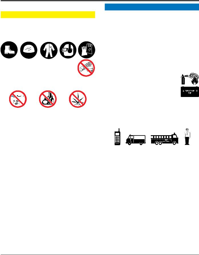
neveR operate this equipment without proper protective clothing, shatterproof glasses, respiratory protection, hearing protection, steel-toed boots and other protective devices required by the job or city and state regulations.
neveR operate this equipment when not feeling well due to fatigue, illness or when under medication.
neveR operate this equipment under the infl uence of drugs or alcohol.
ALWAYS check the equipment for loosened threads or bolts before starting.
dO nOT use the equipment for any purpose other than its intended purposes or applications.
ALWAYS clear the work area of any debris, tools, etc. that would constitute a hazard while the equipment is in operation.
 NOTICE
This equipment should only be operated by trained and qualifi ed personnel 18 years of age and older.
Whenever necessary, replace nameplate, operation and safety decals when they become diffi cult read.
Manufacturer does not assume responsibility for any accident due to equipment modifi cations. Unauthorized equipment modifi cation will void all warranties.
neveR use accessories or attachments that are not recommended by Multiquip for this equipment. Damage to the equipment and/or injury to user may result.
ALWAYS know the location of the nearest fi re extinguisher.
ALWAYS know the location of the nearest fi rst aid kit.
ALWAYS know the location of the nearest phone or keep a phone on the job site.Also, know the phone numbers of the nearest ambulance,doctor and fi re department.
This information will be invaluable in the case of an emergency.
mvh406dsz/dsCPAs pLATE COMPACTOR • operation and parts manual — rev. #7 (02/28/14) — page 7

Safety Information
COMPACTOR SAFETY  dangeR
neveRoperate the equipment in an explosive atmosphere or near combustible materials.An explosion or fi re could result causing severe bodily harm or even death.
 WaRning
neveR disconnect any emergency or safety devices.
These devices are intended for operator safety. Disconnection of these devices can cause severe injury, bodily harm or even death. Disconnection of any of these devices will void all warranties.
 CauTiOn
neveR lubricate components or attempt service on a running machine.

 NOTICE
ALWAYS keep the machine in proper running condition.
Fix damage to machine and replace any broken parts immediately.
ALWAYS store equipment properly when it is not being used. Equipment should be stored in a clean, dry location out of the reach of children and unauthorized personnel.
engine saFeTY  dangeR
The engine fuel exhaust gases contain poisonous carbon monoxide. This gas is colorless and odorless, and can cause death if inhaled.
The engine of this equipment requires an adequate free fl ow of cooling air. neveR operate this equipment in any enclosed or narrow
area where free fl ow of the
air is restricted. If the air fl ow is restricted it will cause injury to people and property and serious damage to the equipment or engine.
 WaRning
dO nOT place hands or fingers inside engine compartment when engine is running.
neveR operate the engine with heat shields or guards removed.
Keep fi ngers, hands hair and clothing away  from all moving parts to prevent injury.
dO nOT remove the radiator cap while the
engine is hot. High pressure boiling water will gush out of the radiator and severely scald any persons in the general area of the compactor.
dO nOT remove the coolant drain plug  while the engine is hot. Hot coolant will

 gush out of the coolant tank and severely

 scald any persons in the general area of
 the compactor.
dO nOT remove the engine oil drain plug while the engine is hot. Hot oil will gush out of the oil tank and severely scald any persons in the general area of the compactor.
 CauTiOn
neveR touch the hot exhaust manifold, muffl er or cylinder. Allow these parts to cool
before servicing equipment.
 NOTICE
neveR run engine without an air fi lter or with a dirty air fi lter. Severe engine damage may occur. Service air fi lter frequently to prevent engine malfunction.
neveR tamper with the factory settings of the engine or engine governor. Damage to the engine or equipment can result if operating in speed ranges above the maximum allowable.
neveR tip the engine to extreme angles during lifting as it may cause oil to gravitate into the cylinder head, making the engine start diffi cult.
page 8 — mvh406dsz/dsCPAs pLATE COMPACTOR • operation and parts manual — rev. #7 (02/28/14)
FueL saFeTY  dangeR
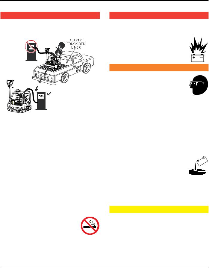
dO nOT add fuel to equipment if it is placed inside truck bed with plastic liner. Possibility exists of explosion or fi re due to static electricity.
MVH-306 |
MVH-306
dO nOT start the engine near spilled fuel or combustible fl uids. Diesel fuel is extremely fl ammable and its vapors can cause an explosion if ignited.
ALWAYS refuel in a well-ventilated area, away from sparks and open fl ames.
ALWAYS use extreme caution when working with fl ammable liquids.
dO nOT fi ll the fuel tank while the engine is running or hot.
dO nOT overfi ll tank, since spilled fuel could ignite if it comes into contact with hot engine parts or sparks from the ignition system.
Store fuel in appropriate containers, in well-ventilated areas and away from sparks and fl ames.
neveR use fuel as a cleaning agent.
dO nOT smoke around or near the equipment. Fire or explosion could result from fuel vapors or if fuel is spilled on a
hot engine.
Safety Information
BaTTeRY saFeTY (eLeCTRiC sTaRT OnLY)  dangeR
dO nOT drop the battery. There is a possibility that the battery will explode.
dO nOTexpose the battery to open fl ames, sparks, cigarettes, etc.The battery contains combustible gases and liquids. If these
gases and liquids come into contact with a fl ame or spark, an explosion could occur.
 WaRning
ALWAYS wear safety glasses when handling the battery to avoid eye irritation.
The battery contains acids that can cause injury to the eyes and skin.
Use well-insulated gloves when picking up the battery.
ALWAYS keep the battery charged. If the battery is not charged, combustible gas will build up.
dO nOT charge battery if frozen. Battery can explode. When frozen, warm the battery to at least 61°F (16°C).
ALWAYS recharge the battery in a well-ventilated environment to avoid the risk of a dangerous concentration of combustible gases.
If the battery liquid (dilute sulfuric acid) comes into contact with clothing or skin, rinse skin or clothing immediately with plenty of water.
If the battery liquid (dilute sulfuric acid) comes into contact with eyes, rinse eyes immediately with plenty of water and contact the nearest doctor or hospital to seek medical attention.
 CauTiOn
ALWAYS disconnect the negaTive battery terminal before performing service on the equipment.
ALWAYS keep battery cables in good working condition. Repair or replace all worn cables.
mvh406dsz/dsCPAs pLATE COMPACTOR • operation and parts manual — rev. #7 (02/28/14) — page 9

Safety Information
TRanspORTing saFeTY
 CauTiOn
NEVER allow any person or animal to stand underneath the equipment while lifting.

 NOTICE
Before lifting, make sure that the equipment parts (hook and vibration insulator) are not damaged and screws are not loose or missing.
Always make sure crane or lifi tng device has been properly secured to the lifting bail (hook) of the equipment.
ALWAYS shutdown engine before transporting.
neveR lift the equipment while the engine is running.
Tighten fuel tank cap securely and close fuel cock to prevent fuel from spilling.
Use adequate lifting cable (wire or rope) of suffi cient strength.
Use one point suspension hook and lift straight upwards.
dO nOT lift machine to unnecessary heights.
ALWAYS tie down equipment during transport by securing the equipment with rope.
enviROnmenTaL saFeTY/deCOmmissiOning

 NOTICE
Decommissioning is a controlled process used to safely retire a piece of equipment that is no longer serviceable. If the equipment poses an unacceptable and unrepairable safety risk due to wear or damage or is no longer cost effective to maintain (beyond life-cycle reliability) and is to be decommissioned (demolition and dismantlement),be sure to follow rules below:
dO nOT pour waste or oil directly onto the ground, down a drain or into any water source.
Contact your country's Department of
Public Works or recycling agency in your area and arrange for proper disposal of any electrical components, waste or oil associated with this equipment.
When the life cycle of this equipment is over, remove battery and bring to appropriate facility for lead reclamation. Use safety precautions when handling batteries that contain sulfuric acid.
When the life cycle of this equipment is over, it is recommended that the trowel frame and all other metal parts be sent to a recycling center.
Metal recycling involves the collection of metal from discarded products and its transformation into raw materials to use in manufacturing a new product.
Recyclers and manufacturers alike promote the process of recycling metal. Using a metal recycling center promotes energy cost savings.
emissiOns inFORmaTiOn
 NOTICE
The diesel engine used in this equipment has been designed to reduce harmful levels of carbon monoxide (CO), hydrocarbons (HC) and nitrogen oxides (NOx) contained in diesel exhaust emissions.
This engine has been certifi ed to meet US EPA Evaporative emissions requirements in the installed confi guration.
Attempting to modify or make adjustments to the engine emission system by unauthorized personnel without proper training could damage the equipment or create an unsafe condition.
Additionally, modifying the fuel system may adversely affect evaporative emissions, resulting in fi nes or other penalties.
emission Control Label
The emission control label is an integral part of the emission system and is strictly controlled by regulations.
The label must remain with the engine for its entire life.
If a replacement emission label is needed, please contact your authorized Kohler Engine Distributor.
page 10 — mvh406dsz/dsCPAs pLATE COMPACTOR • operation and parts manual — rev. #7 (02/28/14)
SPECIFICATIONS
Table 1. MVH406DSZ/DSCPAS Reversible
Plate Compactor Specifications
Centrifugal Force |
12,346 lbs. (5,600 kg) |
|
Vibration Frequency |
4,600 vpm (77 Hz) |
|
Traveling Speed |
0 to 75 ft/min (0 to 23 m/min) |
|
Plate Size (L x W) |
35.43 x 19.69 in (90 x 50 cm) |
|
External Plate Size (L x W) |
35.43 x 25.59 in (90 x 65 cm) |
|
Max. Area of Compaction (no extensions) |
7,510 sq. ft. (2,289 sq. meters) |
|
Length (handle in working position) |
63.39 in (1610 mm) |
|
Height (handle in working position) |
41.34 in |
(1050 mm ) |
Length (handle in vertical position) |
37.6 in |
(955 mm ) |
Height (handle in vertical position) |
55.12 in |
(1400 mm ) |
Operating Weight (without extension plates) |
903.88 lbs. (410 kg) |
|
Operating Weight (with extension plates) |
948 lbs. (430 kg) |
|
Lubricating Oil in Vibration Case |
20.28 fl. oz. (600 cc) |
|
Table 2. Engine Specifications
Engine Make |
FUJI HEAVY INDUSTRIES |
Engine Model |
Robin D1B40T92040 |
Engine Type |
10 HP, Air-cooled 4-cycle Diesel Engine |
Cylinder Bore X Stroke |
3.5 x 3.45 in (88 x 76 mm) |
Displacement |
15.6 fl oz (462 cm3) |
Maximum Ouput |
9.6 HP @3,200 RPM (7.2 kw @3,200 RPM) |
Fuel Tank Capacity |
5.2 quarts (5.0 liters) |
Oil Capacity |
1.6 quarts (1.55 liters) |
Starting Method D/DS |
Recoil/Electric |
Dry Net Weight Recoil/Electric |
118.3 lbs. (53.3 kg) |
Dimensions (L x W x H) |
12.40 x 15.51 x 18.89 in (315 x 394 x 480 mm) |
mvh406dsz/dsCPAs pLATE COMPACTOR • operation and parts manual — rev. #7 (02/28/14) — page 11
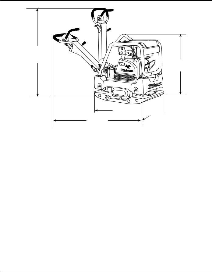
dimensions
A
MVH-406
E
C  B
B 
D
Figure 1. MVH406DSZ/DSCPAS Reversible Plate
Compactor Dimensions
|
Table 3. Dimensions |
|
A |
|
55.12 in. (140 mm.) |
|
|
|
B |
|
19.69 in. (50 cm.) |
|
|
|
C |
|
35.3 in. (90 cm.) |
|
|
|
D |
|
63.39 in. (161 cm.) |
|
|
|
E |
|
41.34 in. (105 cm.) |
|
|
|
page 12 — mvh406dsz/dsCPAs pLATE COMPACTOR • operation and parts manual — rev. #7 (02/28/14)

general nformation
Plate Compactor
The Mikasa MVH406DSZ/DSCPAS is a walk behind, reversible plate compactor designed for the compaction of sand, clay and asphalt. This plate compactor is a powerful compacting tool capable of applying a tremendous force in consecutive high frequency vibrations to a soil surface. Its applications include soil compacting for road, embankments and reservoirs as well as backfilling for gas pipelines, water pipelines and cable installation work.
Vibratory Plates
The vibratory plates of this plate compactor produce low amplitude high frequency vibrations, designed to compact granular soils.
The resulting vibrations cause forward motion. The engine and handle are vibration isolated from the vibrating plate. The heavier the plate, the more compaction force it generates.
Reversible Vibratory Plates
Reversible vibratory plates have two eccentric weights that allow a smooth transition for forward and reverse travel, plus increased compaction force as the result of dual weights.
Due to their weight and force, reversible plates are ideal for semi-cohesive soils.
Frequency/Speed
The compactor's vibrating plate maximum frequency is 4600 vpm (vibrations per minute).The forward and reverse travel speed of the compactor is approximately 75 ft./minute (23 meters/minute).
Engine
This plate compactor is equipped with a ROBIN 1B40, 10 HP, air-cooled 4-cycle diesel engine.
Controls
Before starting this plate compactor, identify and understand the function of the controls and all components.
mvh406dsz/dsCPAs pLATE COMPACTOR • operation and parts manual — rev. #7 (02/28/14) — page 13
components
16
10 2
1
4
14 |
12 |
15
3 |
406 |
|
|
|
6 |
|
5 |
9
7
13
12
11
8
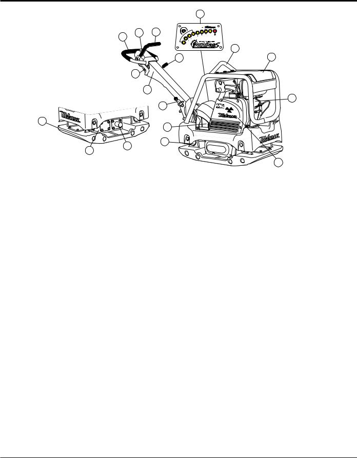
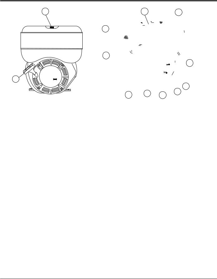
Figure 2. MVH406DSZ/DSCPAS Reversible Plate Compactor Components
Figure 2 illustrates the location of the major components for the MVH406DSZ/DS2CPAS Reversible Plate Compactor. The function of each component is described below:
1.Hand Grip – When operating the compactor use this hand grip to maneuver the compactor.
2.Forward & Reverse Lever – Push the lever forward, the compactor will move in a forward direction, pull the lever backwards, the compactor will move in backwards direction. Placing the lever in the middle (midway) will cause the compactor not to move (neutral).
3.Handle Bar – When operating the compactor, this
handle is to be in the downward position. When the compactor is to be stored, move the handle bar to the upright position.
4.Guard Hook - Used to lift the machine with crane or other lifting device.
5.Stopper - Locks the handle in place in the upward position for stowing.
6.Engine – This plate compactor uses a ROBIN D1B40T92040 diesel engine. Refer to the owner’s manual for engine information and related topics.
7.Battery (Option) - This unit uses a 12-volt battery. See maintenance of this manual for proper care of battery.
8.Belt Cover – Remove this cover to gain access to the V-belts. NEVER run the compactor without the V-belt cover. If the V-belt cover is not installed, the possibility exist that your hand may get caught between the V-belt and clutch, thus causing serious injury and bodily harm.
9.Base Plate – Designed to compact sand, clay, and asphalt.
10.Oil Reservoir– Fill with Shell Tellus Oil 46 or equivalent grade hydraulic oil.
11.Vibration Case – Encloses the eccentric, gears and counter weights.
12.Hydraulic Cylinder – Activated by moving the travel lever. The cylinder controls the direction of movement by the plate compactor.
13.Shock Absorber – Protects plate compactor from damage by absorbing vibration during operation.
14.Throttle Lever – Controls speed of the plate compactor. Place straight vertically to start, push fully counterclockwise for full throttle and fully clockwise to stop plate compactor.
15.Ignition Switch (Option) – Provided for electric start models only.
16.COMPAS – Compaction Analysing System, monitors soil stiffness. Available only on the MVH406DSCPAS.
page 14 — mvh406dsz/dsCPAs pLATE COMPACTOR • operation and parts manual — rev. #7 (02/28/14)
basic engine
2 |
3 |
4 |
11
ROBIN DIESEL
11
5
|
scs |
1 |
ROBIN |
DIESEL |
6
10 9 8 7
FRONT VIEW |
REAR VIEW |
Figure 3. Robin D1B40T92040 Diesel Engine Components
ENGINE COMPONENTS
Figure 3 illustrates the location of the major components for the ROBIN D1B40T92040 diesel engine. The function of each component is described below
1.Recoil Starting Handle (pull rope) – Type of engine starting method. Alternate type would be electric start (ignition key).
2.Fuel Filler Cap/Fuel Tank – Remove this cap to add diesel fuel to the fuel tank. Make sure cap is tighten securely. DO NOT over fill. Fuel tank capacity is 5.3 quarts (5.0 liters)..
3.Engine LiftingStraps/Cover– Remove the air cleaner cover, then lift this cover (the one with decals on it) to gain access to the engine lifting straps.
4.Air Cleaner/Cover – Prevents dirt and other debris from entering the fuel system. Remove wing-nut on top of air filter cannister to gain access to filter element.
5.Speed Control Lever – This lever is connected to the throttle control which is located on the compactor handle bar. This lever to controls engine speed.
6.Oil Filler Cap / Dipstick – Remove this cap to add oil to the engine crankcase. Read dipstick to determine if oil level is low. DO NOT over fill lever to control engine speed. Engine oil capacity is 1.6 quarts (1.55 liters).
7.Engine Motor Mounts – Secure these engine mounts to the compactor frame. Tighten securely.
8.Oil Suction Filter – Remove this bolt to gain access to the internal oil suction filter. Service the oil suction filter as recommended in the maintenance section of this manual.
9.Oil Drain Plug – Unscrew plug to drain oil from engine crankcase. Dispose of oil in a safe manner.
10.Crankshaft – Connect this shaft to the input of the transmission.
11.Muffler – Used to reduce noise and emissions.
12.Engine Nameplate – Contains information about the engine.
mvh406dsz/dsCPAs pLATE COMPACTOR • operation and parts manual — rev. #7 (02/28/14) — page 15

INSPECTION
Before Starting
1. Read safety instructions at the beginning of manual.
2.Familiarize yourself with the operating and control elements of the machine and the working environment. This includes obstacles in the working area, bearing capacity of the ground and the necessary safety provisions.
3.Check the air filter for dirt and dust. If air filter is dirty, replace air filter with a new one as required.
4.Check fastening nuts and bolts for tightness. Loose threads may cause damage to the machine when vibrating.
5.Understand the geographical features and regulations of the job site.
6.Clean the compactor, removing dirt and dust. Particularly, the bottom of the plate, engine cooling air inlet.
Checking Engine Oil Level
1.To check the engine oil level, place the compactor on secure level ground with the engine stopped.
2.Remove the dipstick from the engine oil filler hole (Figure 4) and wipe it clean.
3.Insert and remove the dipstick without screwing it into the filler neck. Check the oil level shown on the dipstick.
Figure 5. Engine Oil Level
Table 4. Oil Tyoe
Season |
Temperature |
Oil Type |
|
|
|
|
|
Summer |
25°C or Higher |
SAE 10W-30 |
|
|
|
|
|
Spring/Fall |
25°C~10°C |
SAE 10W- |
|
30/20 |
|||
|
|
||
Winter |
0°C or Lower |
SAE 10W-10 |
|
|
|
|
Checking the Hydraulic Oil Level
1.To check the engine oil level, place the compactor on secure level ground with the engine stopped.
2.Remove the hydraulic oil breather cap located at the top of the hydraulic oil tank (Figure 6).
3.Using a 24 mm wrench, remove the hydraulic oil filler plug.
4.Visually inspect to determine if hydraulic oil level is low. If oil level is low add Shell Tellus 32 hydraulic oil or equivalent through the hand pump oil filler port.
OIL
BREATHER TANK
CAP
Figure 4. Engine Oil Dipstick Removal
4.If the oil level is low (Figure 5), fill to the edge of the oil filler hole with the recommended oil type (Table 4). Maximum oil capacity is 1.16 quarts (1.10 liters).
HYDRAULIC
OIL PLUG
(24 MM WRENCH)
Figure 6. Hydraulic Oil Filler Plug Removal
page 16 — mvh406dsz/dsCPAs pLATE COMPACTOR • operation and parts manual — rev. #7 (02/28/14)
INSPECTION
 CAUTION
DO NOT overfill hydraulic oil tank. This could cause oil leaks and sluggish operation. Clean cap and surrounding area before opening to prevent dirt from entering oil tank.
5.When adding hydraulic oil, only fill to the specified oil level as marked on the front of the hydraulic oil tank (Figure 7). DO NOT overfill.
OIL
TANK
OIL LEVEL
Figure 7. Oil Tank (Front View)
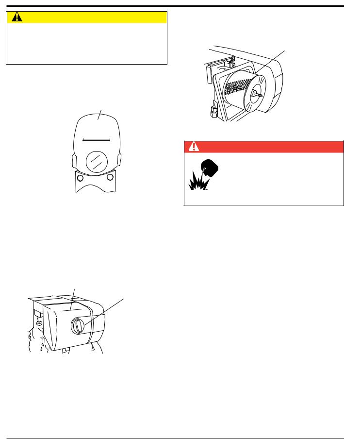
Checking the Air Cleaner
1.To check the engine oil level, place the compactor on secure level ground with the engine stopped.
2.Loosen the wing nut (Figure 8), remove the air cleaner cover.
AIR
CLEANER
WING
NUT
Figure 8. Checking the Air Cleaner
3.Remove the air cleaner element (Figure 9) and inspect it for signs of wear or dirt. If air cleaner element is dirty, clean or replace element.
ELEMENT
Figure 9. Air Cleaner Element
 DANGER
EXPLOSIVE FUEL!
Motor fuels are highly flammable and can be dangerous if mishandled. DO NOT smoke while refueling. DO NOT attempt to refuel if the engine is hot or running.
CheckingThe Fuel
1.Remove the fuel cap located on top of fuel tank.
2.Visually inspect to see if fuel level is low. If fuel is low, replenish with diesel fuel (Figure 10 ).
3.When refueling, be sure to use a strainer for filtration. DO NOT top-off fuel. Wipe up any spilled fuel.
Figure 10. Refueling
mvh406dsz/dsCPAs pLATE COMPACTOR • operation and parts manual — rev. #7 (02/28/14) — page 17
operation
 CAUTION
DO NOT attempt to operate the compactor until the Safety, General Information and Inspection sections of this manual have been read and thoroughly understood.
This section is intended to assist the operator with the initial start-up of the compactor. It is extremely important that this section be read carefully before attempting to use the compactor in the field.
Refer to Figure 3 for the location of controls and components.
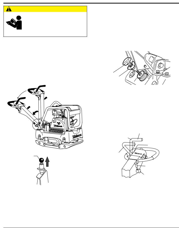
Releasing the Handle
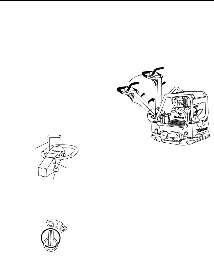
1.Pull the handle release pin, (Figure 11) then push down on the hand grip to release the handle.
MVH-406
HANDLE
RELEASE
PIN PULL UP
TO RELEASE
HANDLE
Figure 11. Handle Release Pin
Adjusting Handle Height
The height of the handle is adjustable for your comfort .
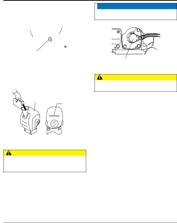
1.Loosen the butterfly screw (Figure 12).
2.Turn the grip clockwise to raise the handle or counterclockwise to lower the handle.
3.When the handle is raised to the desired height, tighten the butterfly screw.
Figure 12. Handle Adjustment
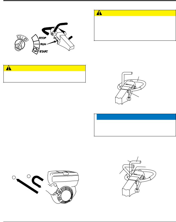
STARTINGTHE ENGINE
Electric Start (Option)
4.Place the throttle lever (Figure 13) in the START position (center). Place the travel lever in the neutral
position (center).
TRAVEL
LEVER
NEUTRAL

 REVERSE
FORWARD
THROTTLE
LEVER
START
(CENTER POSITION)
Figure 13. Travel/Throttle Lever
(Start Position)
5. Insert the ignition key into the ignition switch and turn it to the RUN position (Figure 14). The buzzer should sound at this time.
6. Turn the ignition key further to the right to the START position to start the engine. Buzzer stops sounding and the engine starts.
page 18 — mvh406dsz/dsCPAs pLATE COMPACTOR • operation and parts manual — rev. #7 (02/28/14)
operation
7.If the engine fails to start, DO NOT continue to rotate the ignition key for more than 5 seconds. Return the key to the RUN position and wait 10 seconds before starting again
 STOP
STOP

RUN
START
Figure 14. Starter Switch (Option)
 CAUTION
While the engine is running, never try to turn the ignition key to the START position.
8.After starting the engine, continue to warm up the engine for about 3 to 10 seconds especially in cold weather.
9.If the buzzer does not stop sounding after the engine has started, shutdown engine immediately and check engine oil level. The buzzer functions as a engine oil level alarm warning device.
Recoil Start
1.Place the throttle lever (Figure 13) in the START position (center).
2.Place the travel lever in the neutral position (center).
3.Grasp the starter grip (Figure 15) and slowly pull it out. The resistance becomes the hardest at a certain position, corresponding to the compression point. Pull the starter grip briskly and smoothly for starting.
2 1
Figure 15. Engine Start Handle
4. If the engine does not start, repeat steps 1 through 3.
LING
 CAUTION
Make sure to follow all safety rules referenced in the safety section of this manual before operating compactor. Keep work area clear of debris and other objects that could cause damage to the compactor or bodily harm.
1.Grasp the compactor's hand grip, and move the engine throttle lever (Figure 16) quickly to the fast position.
2.With the throttle lever in the fast position, the engine speed should be around 3,600 RPM, therefore engaging the centrifugal clutch.
HAND
GRIP
FULL THROTTLE
POSITION
Figure 16. Throttle Lever (Fast)
 NOTICE
ALWAYS move the throttle lever quickly without hesitation, because increasing the engine speed slowly causes the clutch to slip.
3.To make the compactor move in the forward direction push the travel lever ( Figure 17) forward.
TRAVEL
LEVER
NEUTRAL

 REVERSE
FORWARD
Figure 17. Travel Lever
mvh406dsz/dsCPAs pLATE COMPACTOR • operation and parts manual — rev. #7 (02/28/14) — page 19
4.To make the compactor move in the reverse direction pull the travel lever ( Figure 17) backwards.
5.Firmly gasp the compactor's hand grip, the compactor will begin moving in the desired position when the direction lever has been placed in the desired position.
6.Slowly walk behind the compactor and be on the lookout for any large objects or foreign matter that might cause damage to the compactor or bodily injury.
7.If travel lever is placed in the neutral position, the machine will vibrate in place.
8.To move the compactor laterally, hold the hand grip firmly and swing compactor. DO NOT swing compactor while gripping the travel lever.
Normal Shutdown
1.Return the throttle lever to the START position (Figure 13). Allow the machine to cool down for 2 to 3 minutes.
2.Place the travel lever in the NEUTRALposition (Figure 18).
3.Place the throttle lever in the STOP position (Figure 18) to stop the engine.
 TRAVEL
LEVER
NEUTRAL
POSITION
STOP
POSITION
THROTTLE
LEVER
Figure 18. Throttle Lever (Stop)
4.If using an electric start unit, return the key switch to the STOP position (Figure 19) as soon as the engine stops.
Figure 19. Starter Switch (STOP)
operation
Emergency Shutdown
1.For a recoil start type engine, move the throttle lever quickly to the STOP position.
2.For an electric start type engine, place the engine ignition switch in the OFF position.
Stowing the Handle
1.Push up the handle upward (Figure 20) until the handle locks in place.
MVH-406
Figure 20. Stowing The Handle
page 20 — mvh406dsz/dsCPAs pLATE COMPACTOR • operation and parts manual — rev. #7 (02/28/14)
operation
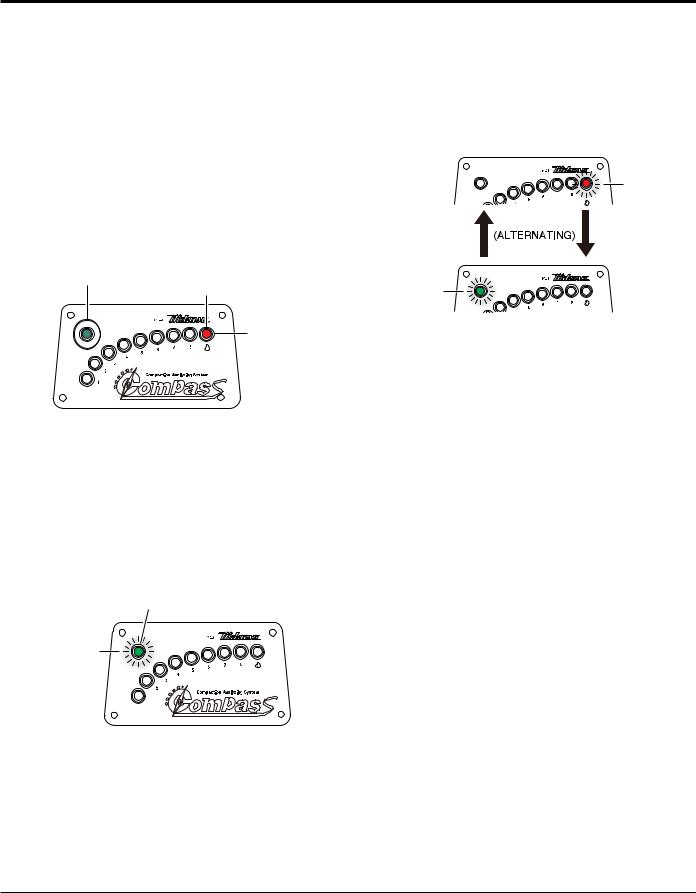
COMPACTION SENSOR (MVH406 DSCPAS Only)
Compaction Analyzing System (COMPAS) is a system that uses an acceleration sensor to show real-time soil stiffness via LED's (light-emitting diode) turning on with each pass of the compactor.
This COMPAS improves compaction work efficiency because it can prevent an already properly compacted area from being compacted more than necessary and identify an area where more compaction is needed.
COMPAS also has a function to detect abnormalities such as vibration trouble (insufficient vibration frequency), ground trouble (soft soil) and other functional issues (Figure 21).
NORMAL OPERATION |
COMPACTION LIMIT |
(GREEN LED ON) |
LED’S 1 THRU 8 ON |
|
PLUS RED LED ON |
VIBRATION ABNORMALITY |
|
(GREEN LED FLASHING) |
SOIL PROBLEM, |
|
|
|
GREEN, AND RED |
|
LED’S ON |
COMPACTION PROGRESSION LED’S 1 THRU 8 ON
Figure 21. Compaction Sensor (COMPAS)

 NOTICE
COMPAS can only show progression of the soil stiffness and is not meant to measure absolute soil density. When using COMPAS always calculate appropriate soil density by conducting proper testing such as plate load test and dynamic load test to best compliment the LED lighting progression with the actual measurement value.
Normal Compaction (Compaction Progression)

 NOTICE
Not all yellow status LEDs will turn on.The progression of the yellow status LEDs depends on the type of soil being compacted. If compacting gravel (stiff soil) potentially all status LEDs will turn ON.
If compacting sand (soft soil), fewer status LED's will turn ON. Remember DO NOT over compact.
When the plate compactor is in idle mode the green LED will begin flashing and the red LED will turn on. As the engine RPM's are increased and compaction begins, the green LED will stop flashing and turn on (solid). The red LED will turn off and the #1 yellow LED will turn on. As compaction progresses the number of yellow LEDs, 2 thru 8 will turn on (Figure 22).
The number of yellow status LEDs that will turn on is soil dependent.
NORMAL OPERATION (GREEN LED ON)
INITIAL COMPACTION YELLOW LED#1 ON
COMPACTION PROGRESSION LED’S 2 THRU 8 ON
Figure 22. Compaction Progression
Normal Compaction (Compaction Limit)
The compaction limit (Figure 23) is achieved when all the yellow LED's 1 thru 8 including the red LED are all on, depending on type of soil being compacted . At this point the machine cannot compact any further. If the compaction results are not satisfactory then check and make sure the soil type, moisture content, lift and number of passes are proper for this machine.
DURING COMPACTION YELLOW
LED’S 1 THRU 8 ON


 RED LED ON
Figure 23. Compaction Limit
mvh406dsz/dsCPAs pLATE COMPACTOR • operation and parts manual — rev. #7 (02/28/14) — page 21
operation
System Diagnostics to Detect Operational Abnormalities
Detection of ground trouble and soft ground
1.For a case of unstable ground or soft ground (soil containing high clay content) for which the use of this machine is not suitable, only the green and red LEDs will be on (Figure 24), with no yellow LED's on.
If this occurs it would be challenging to achieve the desired compaction results. Check to make sure the ground conditions are prepared to specification before proceeding with the compaction process.
GREEN |
GROUND TROUBLE |
|
|
LED ON |
OR |
|
|
|
SOFT GROUND |
|
RED |
|
LED ON |
Figure 24. Ground Trouble or Soft Ground
Detection of Vibration Abnormality
2.When appropriate vibration frequency cannot be achieved during operation due to improper engine RPMs (Figure 25) the green LED will flash. When this occurs check the engine RPMs and the V-belt tension as it could be loose.
VIBRATION ABNORMALITY DUE TO
IMPROPER ENGINE RPM
GREEN LED
FLASHING
Figure 25. Vibration Abnormality
Improper Engine RPM's
Function to Detect Electric System Abnormality
Sensor wire disconnection (between acceleration sensor and sensor panel)
3.If red and green LEDs are flashing alternately as shown in Figure 26 then please check the sensor wire because there is a possibility that it is disconnected.
RED LED
FLASHING
GREEN LED
FLASHING
Figure 26. Sensor Wire Disconnection
Power cable disconnection (between battery and sensor panel)
4.If there are no LEDs on or flashing even when the key switch is turned on then please check the power cable because there is a possibility it is disconnnected.
page 22 — mvh406dsz/dsCPAs pLATE COMPACTOR • operation and parts manual — rev. #7 (02/28/14)

maintenance
 CAUTION
Inspection and other services should always be carried out on hard and level ground with the engine shutdown.
Inspection and Maintenance ServiceTables.
To make sure your plate compactor is always in good working condition before using, carry out the maintenance inspection in accordance with Table 5 thru Table 7.
Table 5. Machine Inspection
Item |
Hours of Operation |
|
|
|
|
Loose or Missing Screws |
Every 8 hours (every day) |
|
|
|
|
Damaged Parts |
Every 8 hours (every day) |
|
|
|
|
Function of Controlling |
Every 8 hours (every day) |
|
System Part |
||
|
||
Hydraulic System Leak |
Every 100 hours |
|
|
|
|
Vibrator Oil Check Every |
Every 100 hours |
|
|
|
|
Vibrator Oil Replacement |
Every 300 hours |
|
|
|
|
Hydraulic Oil Check Every |
Every 100 hours |
|
|
|
|
Hydraulic Oil Replacement |
First after 200 hours, then every |
|
1,000 hours |
||
|
||
V-belt (clutch) Check |
Every 200 hours |
|
|
|
|
Battery Check |
Every 100 hours |
|
|
|
 CAUTION
These inspection intervals are for operation under normal conditions. Adjust your inspection intervals based on the number hours plate compactor is in use, and particular working conditions.

 NOTICE
Fuel piping and connections should be replaced every 2 years.
Table 6. Engine Check |
||
Item |
Hours of Operation |
|
|
|
|
Oil or Fuel Leak |
Every 8 hours (every day) |
|
|
|
|
Tightness of Fastening |
Every 8 hours (every day) |
|
Threads |
||
|
||
|
|
|
Engine Oil Check and Re- |
Every 8 hours (every day) (Re- |
|
plenish to specified maximum |
||
plenishment |
||
level) |
||
|
||
Engine Oil Replacement |
After first 25 hours then every 50 |
|
to 100 hours |
||
|
||
Air Filter Cleaning Every |
100 hours |
|
|
|
|
See separate engine manual for details on engine check.
Daily Service
Check for leakage of fuel or oil.
Check for loose screws including tightness. See Table 7 below (tightening torque ), for retightening:
Table 7. TighteningTorque
(in. kg/cm) Diameter
Material |
6mm |
8mm |
10mm |
12mm |
14mm |
16mm |
18mm |
20mm |
|
|
|
|
|
|
|
|
|
4T |
70 |
150 |
300 |
500 |
750 |
1,100 |
1,400 |
2,000 |
|
|
|
|
|
|
|
|
|
6-8T |
100 |
250 |
500 |
800 |
1,300 |
2,000 |
2,700 |
3,800 |
|
|
|
|
|
|
|
|
|
11T |
150 |
400 |
800 |
1,200 |
2,000 |
2,900 |
4,200 |
5,600 |
*100 300~ 650~
350 700
* (In case counter-part is of aluminum)
(Threads in use with this machine are all right handed)
Material and quality of material is marked on each bolt, and screw.
Remove soil and clean the bottom of compaction plate.
Check hand pump, piping and hose for any leakage. A loosened hydraulic hose can be a cause for leakage. Check hydraulic hose connections with wrench applied for tightness.
Check engine oil.
mvh406dsz/dsCPAs pLATE COMPACTOR • operation and parts manual — rev. #7 (02/28/14) — page 23
maintenance
Engine Oil Replacement:
1.Replace engine oil, in first 25 hours of operation and every 50 to 100 hours afterwards.
2.Oil may be drained more easily when it is warm afteroperation (For more details, see separate engine Owner's Manual).
Air Filter (Every 6 Months or 400 Hours)
1.The air filter element (Figure 27) should be cleaned because a clogged air cleaner can cause poor engine starting, lack of power and shorten engine life substantially.
AIR |
WING |
ELEMENT |
CLEANER |
NUT |
Figure 27. Engine Air Filter and Element
2.To clean or replace air filter loosen the wing nut on the air filter housing (Figure 27) remove the cover and take out air filter cartridge. If only cleaning of the air filter is desired blow through the air filter cartridge from the inside, moving a jet of dry compressed air up and down
all dust is removed.
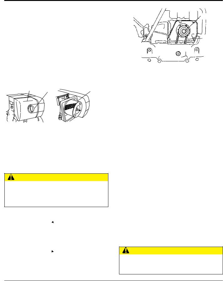
 CAUTION
NEVER attempt to check the V-belt with the engine running. Severe injury can occur if your hand gets caught between the V-belt and the clutch (Figure 28). Always use safety gloves.
CLUTCH
PULLEY
 VIBRATOR
PULLEY
Figure 28. V-Belt Hazard
CLUTCH
V-BELT
VIBRATOR
PULLEY
Figure 29. V-Belt Check
Replacing the V-belt
Remove the belt cover (Figure 29). Engage an offset wrench 3/4”(19 mm) or the like to vibrator pulley (lower) fastening bolt. Engage wastecloth or the like at midway of V-belt on the left side and whilepulling it back strongly, rotate the offset wrench clockwise so that the V-belt will come off.
Reinstalling the V-belt
Engage V-belt to lower vibrator pulley and push the V-belt to leftside of upper clutch and, in the same manner as in removal, rotate offset wrench clockwise so that the V-belt goes back on.
Checking Clutch
Check the clutch simultaneously with V-belt checking. With belt cover removed, check outer drum of the clutch for seizure and "V" groove for wear or damage with your eyes. Clean the "V" groove as necessary. If the shoe is worn, power transmission becomes deficient and slipping will result.
Replacing Clutch
Remove V-belt. Remove bolt at engine power output by giving a light tap with a hammer to an engaged wrench and rotate bolt counterclockwise. Remove clutch with a
extractor. To reinstall, reverse the procedure.
 CAUTION
When ever the compactor's vibration becomes weak or lost during normal operation regardless of operation hours, check the V-belt and clutch immediately.
page 24 — mvh406dsz/dsCPAs pLATE COMPACTOR • operation and parts manual — rev. #7 (02/28/14)
maintenance
Vibrator Oil Level Check

 NOTICE
ALWAYS clean the area around the vibrator oil level check plug before removing oil check plug. This will prevent dirt and debris from entering the system.
1.In every 100 hours of operation, with the machine positioned horizontally, use a 3/4” (19 mm) wrench and remove vibrator oil level guage/dipstick (Figure 30). Visually inspect and see if vibrator oil level is up to filler port. Be sure to clean area around check hole to
prevent dirt and dust from entering.
ADD 10W-30 WT. |
OILGAUGE/ |
MOTOR OIL |
DIPSTICK |
HERE |
|
DRAIN
BOLT
OILGAUGE/
DIPSTICK
CORRECT
DRAIN |
FILL TO 600CC |
|
BOLT |
EXCITER OIL LEVEL CASING NORMAL |
MAXIMUM |
|
|
|
INCORRECT |
|
|
EXCITER OIL LEVEL CASING OVERFILLED
Figure 30. Vibrator Oil Drain and Check Plugs

 NOTICE
The oil fill gauge (dipstick) should be threaded down completely when checking the oil level. Quickly inserting and removing the dipstick from the reservoir will provide inaccurate readings and possibly lead to overfilling the exciter casing.
Overfilling the exciter casing will overload the engine and adversely affect performance. DO NOT OVERFILL 600CC Maximum oil level!
Draining Vibrator Oil
1.Replace vibrator oil after first 200 hours and in every 1,000 hours of operation.
2.Position handle bar vertically (storage position).
3.Using a 14 mm wrench remove the vibrator oil drain plug (Figure 30) from the vibrating plate assembly.
 NOTICE
For draining oil through level check hole, have the machine inclined with a sleeper or the like placed under the compaction plate on opposite side.
4.After hydraulic oil has been completely drained from machine, fill with 10W-30 motor oil to the appropriate safe operating level (Figure 30).
5.Reinstall drain plug into vibrating plate assembly. Apply seal tape or Loctite #575 to thread portion of drain plug.
Draining Hydraulic Oil
1.Disconnect the hydraulic hose (Figure 31) connected to the hydraulic oil cylinder.
2.Push the travel lever back and forth to drain the hydraulic oil from the hand pump (hydraulic oil reservoir).
HYDRAULIC
HOSE
HYDRAULIC
CYLINDER
Figure 31. Hydraulic Oil Cylinder/Hose
3.After draining hydraulic oil, reconnect hydraulic oil hose to cylinder.
4.Place handle in upright position. Pull travel lever all the way back (reverse), and using a rope, secure travel lever to hand grip.
mvh406dsz/dsCPAs pLATE COMPACTOR • operation and parts manual — rev. #7 (02/28/14) — page 25
Adding Hydraulic Oil
1.Remove the breather cap and oil plug (Figure 32) from thehydraulic oil tank using a 24mm hex socket.
OIL
BREATHER TANK
CAP
HYDRAULIC
OIL PLUG
(24 MM WRENCH)
Figure 32. Hydraulic Oil Tank
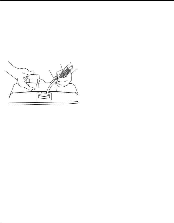
2.Using a funnel, add Shell Tellus Oil #32 or equivalent to the hydraulic oil tank through the oil filler port (Figure 33). Oil tank capacity is 18.7 fl. oz (550 cc).
|
|
|
|
HYDRAULIC |
S |
|
|
|
OIL TANK |
|
|
|
FILL TO |
|
TE EL |
||||
H |
|
|
|
|
|
L |
L |
|
|
0I |
|
L |
|
|
|
U |
THIS LEVEL |
||
L |
#46 |
|||
|
S |
|
||
OIL LEVEL
FRONT VIEW |
REAR VIEW |
Figure 33. Adding Hydraulic Oil
 CAUTION
Make sure hydraulic oil is at a normal safe operating level. DO NOT over fill. Over filling (excessive oil) will cause excess oil to blow out of breather plug.
3.Loosen bleeder plug located at top of hydraulic cylinder on side of vibrator (Figure 34). Air remaining in the circuit will be forced out of the bleeder plug. Once all air has been purged from the hydraulic system, tighten bleeder plug securely
4.Reinsert oil plug into hydraulic oil tank and tighten
securely. Reinstall breather cap.
maintenance
 NOTICE
The bleeder plug should only be loosened, but not removed.
BLEEDER
PLUG
HYDRAULIC
CYLINDER
Figure 34. Bleeder Plug
 CAUTION
ALWAYS wear safety glasses or face mask, protective clothes, and rubber gloves when working with battery.
BATTERY MAINTENANCE (Option)
Mishandling of the battery shortens the service life of the battery and adds to maintenance cost. When handling the battery do the following:
The battery electrolyte contains sulfuric acid, be careful not to let the battery electrolyte come in contact with your body or clothing.
Always check the battery terminals periodically to ensure that they are in good condition.
Always wear eye protection and rubber gloves, since the battery contains sulfuric acid which burns skin and eats through clothing. In case of contact, flush thoroughly with water and contact a doctor immediately.
Use wire brush or sand paper to clean the battery terminals.
Always check battery for cracks or any other damage. If white pattern appears inside the battery or paste has accumulated at the bottom, replace the battery.
If the compactor will not be in operation for a long period of time, store in cool dry place and check the battery charge level every month to maintain the performance of the battery.
page 26 — mvh406dsz/dsCPAs pLATE COMPACTOR • operation and parts manual — rev. #7 (02/28/14)
maintenance
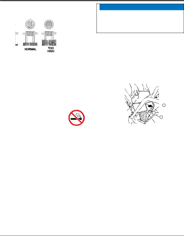
Check the battery regularly and make sure that each electrolyte level is to the bottom of the vent well (Figure 35). If necessary add only distilled water in a well-ventilated area.
Figure 35. Battery Electrolyte Levels
BATTERY CHARGING
DO NOT charge battery with the battery cables connected to the compactor.The diodes will be damage by the high voltage.
Batteries generate hydrogen gas which
can be highly explosive. DO NOT smoke or allow flames or sparks near the battery, especially during charging of the battery.
Charge the battery in a open air environment (plenty of ventilation).
Before charging , remove the cap from each cell of the battery.
Connect the positive (+) lead of the charger to the positive (+) terminal of the battery and the negative (-) lead of the charger to the negative (-) terminal of the battery. DO NOT reverse the polarity when charging. Reverse polarity will damage the charger rectifier or the battery.
Battery fluid will be lost through continuous charging and discharging.
Discontinue charging if the electrolyte temperature exceeds 117° F (45° C).
 NOTICE
During summer much more battery fluid is lost than in winter. Before starting, check battery electrolyte levels and replenish with distilled water to the upper mark on the battery.
BATTERY CABLE CONNECTION (Option)
1.Take off the battery cover by removing the M6 nuts that secure the battery holder to the cover.
2.When removing battery cables, disconnect the ground side (normally negative) first (Figure 36).
3.When installing battery cable connect the ground side
(normally negative) last.
 + TERMINAL
BATTERY COVER
- TERMINAL
BATTERY
Figure 36. Removing Battery Cover
mvh406dsz/dsCPAs pLATE COMPACTOR • operation and parts manual — rev. #7 (02/28/14) — page 27
maintenance
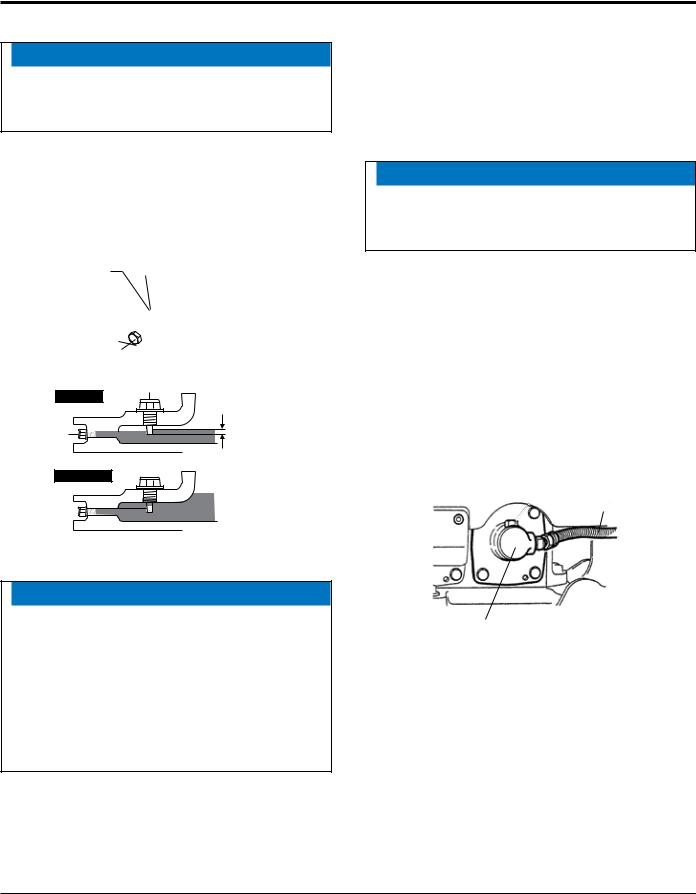
CHECKING FUEL FILTER
1.Clean the fuel filter (Figure 37) every 3 months or 200 hours.
2.Replace fuel filter every 6 months or 400 hours.
3.To clean the fuel filter, loosen the nuts of the fuel cock and pull out the filter from the F.O. tank filler port.Wash the filter thoroughly with diesel fuel oil.
4.Remove fuel supply lines (items 1 and 2) from fuel filter (Figure 39) and install new filter.
FUEL 1
FILTER
2
Figure 37. Fuel Filter
LONGTERM STORAGE
When storing your compactor for long periods do the following:
1.Run the engine at idle speed for 3-5 minutes.
2.Stop the engine. Drain the engine crankcase oil while the engine is still warm. Fill engine crankcase with fresh oil.
3.Wipe any oil or dirt that may have accumulated on the compactor.
4.The new engine can normally be stored dry for up to one year.
5.In very humid climates or coastal regions, the protective treatment is sufficient for up to 6 months.
6.Store compactor in a cool dry place out of the reach of children or unauthorized personnel
Troubleshooting
For futher maintenance please reference compactor and engine troubleshooting tables on proceeding pages.
page 28 — mvh406dsz/dsCPAs pLATE COMPACTOR • operation and parts manual — rev. #7 (02/28/14)

trouble shooting (compactor)
Troubleshooting (Compactor)
symptom |
possible problem |
Solution |
|
|
Clutch slips? |
Adjust or replace clutch. |
|
|
V-belt slips? |
Adjust or replace V-belt. |
|
|
Excessive oil in vibrator? |
Fill to correct level. |
|
Travel speed low and vibration weak. |
|
Check vibrator assembly for any |
|
Trouble in vibrator internals? |
worn or defective parts, replace any |
||
|
|
defective parts. |
|
|
Aeration in hydraulic oil for for travel |
Purge air in hydraulic oil. (Bleed plug) |
|
|
reversing system? |
||
|
|
||
|
Engine speed incorrect? |
Set engine speed to correct RPM. |
|
|
Travel reversing system inoperative? |
Check entire travel system. |
|
|
Reversing lever installation correct? |
Clean installation of reversing lever. |
|
|
Broken or defective oil hose? |
Replace oil hose. |
|
Travels forward or backward but |
Aeration in hydraulic oil for for travel |
Purge air in hydraulic oil. (Bleed plug) |
|
reversing system? |
|||
unable to switch direction. |
|
||
Excessive oil in reversing system? |
Fill to correct level. |
||
|
|||
|
Selector valve clogged with trash? |
Clean selector valve. |
|
|
Cylinder piston bearing failure? |
Check piston bearing in cylinder for |
|
|
leakage at USH packing. |
||
|
|
||
|
V-belt disengaged or slips? |
Engage V-belt, adjust or replace. |
|
Does not travel in forward or reverse |
Clutch slips? |
Adjust clutch, replace if necessary. |
|
Pump input shatkey or adapter key- |
Replace input shatkey or adapter |
||
|
|||
|
way damaged? |
key-way |
|
|
Cylinder piston bearing failure? |
Check piston bearing in cylinder for |
|
|
leakage at USH packing. |
||
|
|
||
Reversing lever operating resistance |
Excessive hydraulic oil? |
Fill to correct level. |
|
great. |
|||
|
|
mvh406dsz/dsCPAs pLATE COMPACTOR • operation and parts manual — rev. #7 (02/28/14) — page 29

trouble shooting (engine)
Troubleshooting (engine)
symptom |
possible problem |
Solution |
|
|
|
|
|
|
No Fuel reaching injection pump? |
Add fuel. Check entire fuel system. |
|
|
|
|
|
|
Defective fuel pump? |
Replace fuel pump. |
|
|
|
|
|
|
Fuel fi lter clogged? |
Replace fuel fi lter and clean tank. |
|
|
|
|
|
|
Faulty fuel supply line? |
Replace or repair fuel line. |
|
|
|
|
|
|
Compression too low? |
Check piston, cylinder and valves. Adjust or |
|
|
repair per engine repair manual. |
||
Engine will not start or start is delayed, |
|
||
|
|
||
Fuel pump not working correctly? |
Repair or replace fuel pump. |
||
although engine can be turned over. |
|||
|
|
||
Oil pressure too low? |
Check engine oil pressure. |
||
|
|||
|
|
|
|
|
Low starting temperature limit exceeded? |
Comply with cold starting instructions and |
|
|
proper oil viscosity. |
||
|
|
||
|
|
|
|
|
Defective battery? |
Charge or replace battery. |
|
|
|
|
|
|
Air or water mixed in fuel system? |
Check carefully for loosened fuel line |
|
|
coupling, loose cap nut, etc. |
||
|
|
||
|
|
|
|
|
Engine oil too thick? |
Refi ll engine crankcase with correct type of |
|
At low temperatures engine will not start. |
oil for winter environment. |
||
|
|||
|
Defective battery? |
Replace battery. |
|
|
|
|
|
Engine fi res but stops soon as starter is |
Fuel fi lter blocked? |
Replace fuel fi lter. |
|
|
|
||
Fuel supply blocked? |
Check the entire fuel system. |
||
switched off. |
|||
|
|
||
Defective fuel pump? |
Replace fuel pump. |
||
|
|||
|
|
|
|
|
Fuel tank empty? |
Add fuel. |
|
|
|
|
|
Engine stops by itself during normal |
Fuel fi lter blocked? |
Replace fuel fi lter. |
|
|
|
||
Defective fuel pump? |
Replace fuel pump. |
||
operation. |
|||
|
|
||
|
Mechanical oil pressure shutdown sensor |
Add oil. Replace low oil shutdown sensor if |
|
|
stops the engine due to low oil? |
necessary. |
|
|
|
|
|
|
Fuel tank empty? |
Replace fuel fi lter. |
|
|
|
|
|
|
Fuel fi lter clogged? |
Replace fuel fi lter. |
|
|
|
|
|
|
Fuel tank venting is inadequate? |
Ensure that tank is adequately vented. |
|
|
|
|
|
|
Leaks at pipe unions? |
Check threaded pipe unions tape and tighten |
|
|
unions a required. |
||
|
|
||
Low engine power, output and speed. |
|
|
|
Speed control lever does not remain in |
See engine manual for corrective action. |
||
|
|||
|
selected position? |
||
|
|
||
|
|
|
|
|
Engine oil level too full? |
Correct engine oil level. |
|
|
|
|
|
|
|
Use No. 2-D diesel fuel only. Check the fuel |
|
|
Injection pump wear? |
injection pump element and delivery valve |
|
|
|
assembly and replace as necessary. |
|
|
|
|
page 30 — mvh406dsz/dsCPAs pLATE COMPACTOR • operation and parts manual — rev. #7 (02/28/14)
 Loading...