


OPERATION AND PARTS MANUAL
WHISPERWATT™ SERIES
MODEL DCA-600SSK
60 Hz GENERATOR
(KOMATSU SA6D170AE-1 DIESEL ENGINE)
PARTS LIST NO. C4875300104C
SERIAL NO. 3692434~
Revision #7 (04/30/10)
To find the latest revision of this publication, visit our website at: www.mqpower.com
THIS MANUAL MUST ACCOMPANYTHE EQUIPMENT AT ALLTIMES.
PROPOSITION 65WARNING
Diesel engine exhaust and some of
PAGE 2 — DCA-600SSK — OPERATION AND PARTS MANUAL (STD) — REV. #7 (04/30/10)

NOTE PAGE
DCA-600SSK — OPERATION AND PARTS MANUAL (STD)— REV. #7 (04/30/10) — PAGE 3

MQ Power DCA-600SSK
AC Generator
Proposition 65 Warning ..................................................... |
2 |
Parts Ordering Procedures ............................................... |
5 |
Specifications Generator/Engine ...................................... |
6 |
Dimensions (Top and Side) ............................................... |
8 |
Dimensions (Front and Rear) ............................................ |
9 |
Safety Alert Messages Symbols............................... |
10-11 |
Rules for Safe Operation ........................................... |
12-15 |
Installation ................................................................. |
16-17 |
Towing Rules for Safe Operation .................................... |
18 |
Trailer Safety Guidelines ................................................. |
19 |
Trailer Specifications ................................................. |
20-21 |
Operation and Safety Decals..................................... |
22-25 |
General Information ........................................................ |
26 |
Major Components ......................................................... |
27 |
Generator Control Panel (Up to S/N 3698616) ................ |
28 |
Generator Control Panel (S/N 3698617~)........................ |
28 |
Generator Control Panel Description ............................... |
29 |
Engine Operating Panel (Up to S/N 3698616) ................. |
30 |
Engine Operating Panel (S/N 3698617~) ........................ |
30 |
Engine Operating Panel Description ............................... |
31 |
Output Terminal Panel Overview ................................ |
32-34 |
Load Application ............................................................. |
35 |
Generator Outputs .......................................................... |
36 |
Generator Outputs/Gauge Reading................................. |
37 |
Output Terminal Panel Connections ........................... |
38-39 |
Pre Setup .................................................................. |
40-44 |
Generator Start-up Procedure (Key Switch) .............. |
45-47 |
Generator Start-up Procedure ( Manual MPEC) ............. |
48 |
Generator Start-up Procedure (Auto MPEC) .................. |
49 |
Generator Shutdown Procedure ...................................... |
50 |
Maintenance .............................................................. |
51-55 |
Trailer Brakes Maintenance ............................................ |
56 |
Trailer Maintenance.................................................... |
57-58 |
Trailer Wiring Diagrams .............................................. |
59-60 |
Generator Wiring Diagram ............................................... |
61 |
Generator Main Breaker Wiring Diagram ......................... |
62 |
Engine Wiring Diagrams ............................................ |
63-64 |
Electronic Governor Controller Wiring Diagram ............... |
65 |
Engine Troubleshooting .............................................. |
66-67 |
GeneratorTroubleshooting .............................................. |
68 |
Engine Contoller Troubleshooting (MPEC) ...................... |
69 |
Explanation of Codes in Remarks Column ..................... |
70 |
TABLE OF CONTENTS
COMPONENT DRAWINGS
Generator Assembly ......................................... |
72-75 |
Control Box Assembly ....................................... |
76-83 |
Engine Radiator Assembly ................................ |
84-87 |
Engine Operating Panel Assembly ................... |
88-89 |
Output Terminal Assembly ................................ |
90-93 |
Battery Assembly .............................................. |
94-95 |
Muffler Assembly .............................................. |
96-97 |
Fuel Tank Assembly .......................................... |
98-99 |
Enclosure #1 Assembly................................. |
100-101 |
Enclosure #2 Assembly................................. |
102-105 |
Enclosure #3 Assembly................................. |
106-107 |
Enclosure (Rubber Seals) ............................. |
108-109 |
Name Plate and Decals ................................ |
110-113 |
Terms and Conditions Of Sale — Parts ............... |
114 |
Specification and part number are subject to change without notice.
PAGE 4 — DCA-600SSK — OPERATION AND PARTS MANUAL (STD) — REV. #7 (04/30/10)
www.mqpower.com
PARTS ORDERING PROCEDURES
|
|
|
|
|
|
Ordering parts has never been easier! |
||||||||
|
|
|
|
|
|
|
Choose from three easy options: |
|||||||
|
|
|
|
|
|
|
|
|
|
|
|
Effective: |
||
|
|
|
|
|
|
|
|
|
|
|
|
January 1st, 2006 |
||
Best Deal! Order via Internet (Dealers Only): |
|
|
If you have an MQ Account, to obtain a Username |
|||||||||||
|
|
|
Order parts on-line using Multiquip’s SmartEquip website! |
|
|
|||||||||
|
|
|
|
|
and Password, E-mail us at: parts@multiquip. |
|||||||||
|
|
|
|
N View Parts Diagrams |
|
|
com. |
|||||||
|
|
|
|
N Order Parts |
|
|
To obtain an MQ Account, contact your |
|||||||
|
|
|
|
N Print Specification Information |
|
|
District Sales Manager for more information. |
|||||||
|
|
|
|
|
|
|
|
|
|
|
||||
|
|
|
|
|
Goto www.multiquip.com and click on |
|
|
Use the internet and qualify for a 5% Discount |
|
|||||
|
|
|
|
|
|
|
|
|||||||
|
|
|
|
|
|
|
|
|
|
|
|
on Standard orders for all orders which include |
||
|
|
|
|
|
|
Order |
Parts |
to log in and save! |
||||||
|
|
|
|
|
|
|
|
|
|
|
|
complete part numbers.* |
||
|
|
|
|
|
|
|
|
|
|
|||||
|
|
|
|
|
|
|
|
|
|
|
|
|
|
|
|
|
|
|
|
|
|
|
|
|
|
|
Note: Discounts Are Subject To Change |
||
|
|
|
|
|
|
|
|
|
||||||
|
|
|
|
|
|
Order via Fax (Dealers Only): |
|
|
|
|
|
|
||
|
|
|
|
|
|
|
|
Fax your order in and qualify for a 2% Discount |
|
|||||
|
|
|
|
|
|
All customers are welcome to order parts via Fax. |
|
on Standard orders for all orders which include |
||||||
|
|
|
|
|
|
|
||||||||
|
|
|
|
|
|
Domestic (US) Customers dial: |
|
complete part numbers.* |
||||||
|
|
|
|
|
|
1-800-6-PARTS-7 (800-672-7877) |
|
|
|
|
|
|
||
|
|
|
|
|
|
|
|
|
Note: Discounts Are Subject To Change |
|||||
|
|
|
|
|
|
|
|
|
||||||
|
|
|
|
|
|
|
|
|
|
|
|
|||
|
|
|
|
|
|
|
|
|
|
|
|
|
|
|
|
|
|
|
|
|
|
Order via Phone: Domestic (US) Dealers Call: |
|||||||||||
|
|
|
|
|
|
|||||||||||||
|
|
|
|
|
|
|
|
|
|
|
|
|
1-800-427-1244 |
|
|
|||
|
|
|
|
|
|
|
|
|
|
|
|
|
|
|
|
|
|
|
|
|
|
|
|
|
|
|
|
|
|
|
|
|
|
|
|
|
|
|
|
|
Non-Dealer Customers: |
|
|
|
|
|
|
|
|
|
|
|||||
|
|
|
|
|
|
International Customers should contact |
||||||||||||
|
|
|
Contact your local Multiquip Dealer for |
|
|
|
||||||||||||
|
|
|
|
|
|
their local Multiquip Representatives for |
||||||||||||
|
|
|
parts or call 800-427-1244 for help in |
|
|
|
||||||||||||
|
|
|
|
|
|
|||||||||||||
|
|
|
|
|
|
Parts Ordering information. |
||||||||||||
|
|
|
locating a dealer near you. |
|
|
|
||||||||||||
|
|
|
|
|
|
|
|
|
||||||||||
|
|
|
|
|
|
|
|
|
|
|
|
|
|
|
|
|||
|
|
|
When ordering parts, please supply: |
|||||||||||||||
R |
Dealer Account Number |
R Specify Preferred Method of Shipment: |
|
R |
Dealer Name and Address |
UPS/Fed Ex |
DHL |
R |
Shipping Address (if different than billing address) |
N Priority One |
Truck |
R |
Return Fax Number |
N Ground |
|
N Next Day |
|
||
R |
Applicable Model Number |
|
|
N Second/Third Day |
|
||
|
|
|
|
RQuantity, Part Number and Description of Each Part
 NOTICE
All orders are treated as Standard Orders and will ship the same day if received prior to 3PM PST.
WE ACCEPT ALL MAJOR CREDIT CARDS!
DCA-600SSK — OPERATION AND PARTS MANUAL (STD)— REV. #7 (04/30/10) — PAGE 5

|
|
DCA-600SSK — SPECIFICATIONS |
|||
|
|
|
|
|
|
|
|
|
|
|
|
|
|
Table 1. Generator Specifications |
|
|
|
|
|
|
|
|
|
|
Model |
DCA-600SSK |
|
|
|
|
|
|
|
|
|
|
Type |
Revolving field, self ventilated, drip proof, single bearing |
|
||
|
|
|
|
|
|
|
Armature Connection |
Star with Neutral |
|
|
|
|
|
|
|
|
|
|
Phase |
3 |
|
|
|
|
|
|
|
|
|
|
Standby Output |
528 KW (660KVA) |
|
|
|
|
|
|
|
|
|
|
Prime Output |
480 KW (600 KVA) |
|
|
|
|
|
|
|
|
|
|
Voltages — 1Ø |
120,127,139,240,254,277 (Adjustable) |
|
|
|
|
|
|
|
|
|
|
Voltages — 3Ø |
208,220,240,416,440,480 (Reconnectable) |
|
|
|
|
|
|
|
|
|
|
Power Factor |
0.8 |
|
|
|
|
|
|
|
|
|
|
Frequency |
60 Hz |
|
|
|
|
|
|
|
|
|
|
Frequency Regulation: |
Isochronous under varying loads from no load to 100% rated load |
|
||
|
No load to full load |
|
|||
|
|
|
|
|
|
|
|
|
|
|
|
|
Frequency Regulation: |
±0.25 of mean value for constant loads from no load to full load |
|
||
|
Steady State |
|
|||
|
|
|
|
|
|
|
|
|
|
|
|
|
Insulation |
Class F |
|
|
|
|
|
|
|
|
|
|
Sound Level dB(A) |
75 |
|
|
|
|
(full load at 23 feet) |
|
|
||
|
|
|
|
|
|
|
|
|
|
|
|
|
Dimensions Approx. |
204.72 x 64.96 x 98.49 in. (5200 x 1650 x 2,500 mm.) |
|
|
|
|
(L x W x H) |
|
|
||
|
|
|
|
|
|
|
|
|
|
|
|
|
Dry Net Weight |
19,553 lbs. (8,869 kg.) |
|
|
|
|
|
|
|
|
|
|
|
Table 2. Engine Specifications |
|
|
|
|
|
|
|
|
|
|
|
KOMATSU SA6D170AE-1 |
|
|
|
|
|
|
|
|
|
|
Type |
direct injection, turbo-charged with after-cooler |
|
|
|
|
|
|
|
|
|
|
No. of Cylinders |
6 cylinders |
|
|
|
|
|
|
|
|
|
|
Bore x Stroke |
6.8 in. x 6.8 in. (170 mm x 170 mm) |
|
|
|
|
|
|
|
|
|
|
Rated Output |
688 HP/1800 rpm |
|
|
|
|
|
|
|
|
|
|
Displacement |
1411.5 cu. in. (23150 cc) |
|
|
|
|
|
|
|
|
|
|
Starting |
Electric |
|
|
|
|
|
|
|
|
|
|
Coolant Capacity |
29.6 gal. (112 liters) |
|
|
|
|
|
|
|
|
|
|
Lube Oil Capacity |
16.1 gal. (60.9 liters) |
|
|
|
|
|
|
|
|
|
|
Fuel Consumption |
33.9 gal. (128.3L)/hr at full load |
|
3/4 load |
|
|
|
|
|
|
|
|
1/2 load |
|
1/4 load |
|
|
|
|
|
|
||
|
|
|
|
|
|
|
|
12V200 Ah x 2 (24V System) |
|
|
|
|
|
|
|
|
|
|
|
#2 Diesel Fuel |
|
|
|
|
|
|
|
|
|
PAGE 6 — DCA-600SSK — OPERATION AND PARTS MANUAL (STD) — REV. #7 (04/30/10)

NOTE PAGE
DCA-600SSK — OPERATION AND PARTS MANUAL (STD)— REV. #7 (04/30/10) — PAGE 7
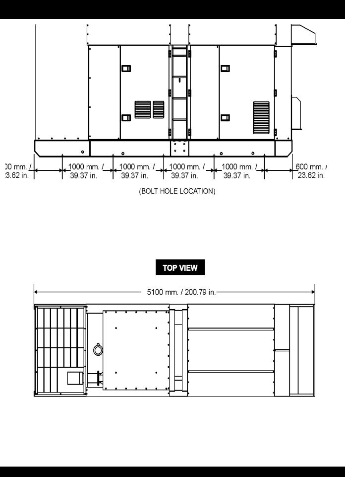
DCA-600SSK — DIMENSIONS (TOP AND SIDE)
Figure 1. Dimensions
PAGE 8 — DCA-600SSK — OPERATION AND PARTS MANUAL (STD) — REV. #7 (04/30/10)
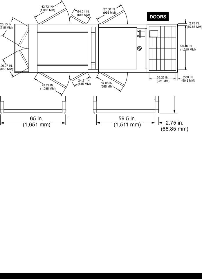
DCA-600SSK — DIMENSIONS (FRONT , REAR AND DOORS)
Figure 2. Dimensions
DCA-600SSK — OPERATION AND PARTS MANUAL (STD)— REV. #7 (04/30/10) — PAGE 9
DCA-600SSK — SAFETY MESSAGE ALERT SYMBOLS
FORYOUR SAFETY AND THE SAFETY OF OTHERS! |
|
HAZARD SYMBOLS |
|
|
|
Safety precautions should be followed at all times when operating this equipment.Failure to read and understand the Safety Messages and Operating Instructions could result in injury to yourself and others.
This Owner's Manual has been NOTE developed to provide complete instructions for the safe and efficient operation of the
MQPower Model DCA-600SSK
WHISPERWATT™ GENERATOR.
Before using this generator, ensure that the operating individual has read and understands all instructions in this manual.
SAFETY MESSAGE ALERT SYMBOLS
The three (3) Safety Messages shown below will inform you about potential hazards that could injure you or others. The Safety Messages specifically address the level of exposure to the operator, and are preceded by one of three words:
DANGER, WARNING, or CAUTION.
DANGER
You WILL be KILLED or SERIOUSLY injured if you do not follow directions.
WARNING
You COULD be KILLED or SERIOUSLY injured if you do not follow directions.
CAUTION
You CAN be injured if you do not follow directions
Potential hazards associated with the operation of this equipment will be referenced with "Hazard Symbols" which appear throughout this manual, and will be referenced in conjunction with Safety "Message Alert Symbols".
WARNING - LETHAL EXHAUST GASES
Gasoline engine exhaust gases contain poisonous carbon monoxide. This gas is colorless and odorless, and can cause DEATH if inhaled. NEVER operate this
equipment in a confined area or enclosed structure that does not provide ample free flow air.
WARNING - EXPLOSIVE FUEL
Gasoline is extremely flammable, and its vapors can cause an explosion if ignited. DO NOT start the engine near spilled fuel or combustible fluids. DO NOT fill the fuel tank while the engine is running or hot.
DO NOT overfill tank, since spilled fuel could ignite if it comes into contact with hot engine parts or sparks from the ignition system. Store fuel in approved containers, in well-ventilated areas and away from sparks and flames. NEVER use fuel as a cleaning agent.
WARNING - BURN HAZARDS
Engine components can generate extreme heat.To prevent burns, DO NOT touch these areas while the engine is running or immediately after operations. NEVER operate the engine with heat shields or heat guards removed.
DANGER - ELECTROCUTION HAZARDS
During operation of this generator, there exists the possibility of electrocution, electrical shock or burn, which can cause severe bodily harm or even DEATH!
PAGE 10 — DCA-600SSK — OPERATION AND PARTS MANUAL (STD) — REV. #7 (04/30/10)
DCA-600SSK — SAFETY MESSAGE ALERT SYMBOLS
WARNING - ROTATING PARTS
NEVER operate equipment with covers, or guards removed. Keep fingers, hands, hair and clothing away from all moving parts to prevent injury.
CAUTION - ACCIDENTAL STARTING
ALWAYS place the Engine ON/OFF switch in the OFF position and remove the ignition key when the pump is not in use.
CAUTION - OVER-SPEED CONDITIONS
NEVER tamper with the factory settings of the engine governor or settings.
Personal injury and damage to the engine or equipment can result if operating in speed ranges above maximum allowable.
This generator, other property, or the surrounding environment could be damaged if you do not follow instructions.
CAUTION - RESPIRATORY HAZARDS
ALWAYS wear approved respiratory protection.
CAUTION - SIGHT AND HEARING HAZARDS
ALWAYS wear approved eye and hearing protection.
CAUTION - EQUIPMENT DAMAGE MESSAGES
Other important messages are provided throughout this manual to help prevent damage to your generator, other property, or the surrounding environment.
DCA-600SSK — OPERATION AND PARTS MANUAL (STD)— REV. #7 (04/30/10) — PAGE 11
DCA-600SSK — RULES FOR SAFE OPERATION
DANGER - READTHIS MANUAL!
Failure to follow instructions in this manual may lead to serious injury or even DEATH! This equipment is to be operated by trained and qualified personnel only! This equipment is for industrial use only.
The following safety guidelines should always be used when operating the DCA-600SSK Whisperwatt™ Generator.
General Safety:
■DO NOT operate or service this equipment before reading this entire manual.
The operator MUST BE familiar with proper safety precautions and operations techniques before using generator.
■This equipment should not be operated by persons under
18 years of age.
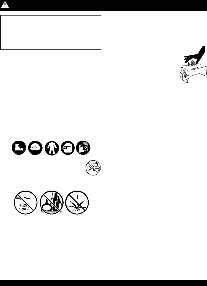
■NEVER operate this equipment without proper protective clothing, shatterproof glasses, steel-toed boots and other protective devices required by the job.
■ NEVER operate this equipment when not feeling well due to fatigue, illness or taking medicine.
■NEVER operate this equipment under the influence or drugs or alcohol.
■NEVER use accessories or attachments, which are not recommended by MQ Power for this equipment.Damage to the equipment and/or injury to user may result.
■Manufacturer does not assume responsibility for any accident due to equipment modifications. Unauthorized equipment modification will void all warranties.
■Whenever necessary, replace nameplate, operation and safety decals when they become difficult read.
■ALWAYS check the machine for loosened threads or bolts before starting.
■NEVER operate the generator in an explosive atmosphere or near combustible materials. An explosion or fire could result causing severe bodily harm or even death.
■NEVER touch the hot exhaust manifold, muffler or cylinder. Allow these parts to cool before servicing engine or generator.
■ HighTemperatures – Allow the engine  to cool before performing service and


 maintenance functions. Contact with
 hot! components can cause serious
burns.
■The engine of this generator requires an adequate free flow of cooling air. NEVER operate the generator in any enclosed or narrow area where free flow of the air is restricted. If the air flow is
restricted it will cause serious damage to the generator or engine and may cause injury to people. The generator engine gives off DEADLY carbon monoxide gas.
■DO NOT place hands or fingers inside generator engine compartment when engine is running.
■NEVER run engine without air filter.Severe engine damage may occur.
■DO NOT leave the generator running in the manual mode unattended.
■Refer to the KOMATSU Engine Owner's Manual for engine technical questions or information.
■ALWAYS store equipment properly when it is not being used. Equipment should be stored in a clean, dry location out of the reach of children.
PAGE 12 — DCA-600SSK — OPERATION AND PARTS MANUAL (STD) — REV. #7 (04/30/10)
DCA-600SSK — RULES FOR SAFE OPERATION
Generator Grounding
To guard against electrical shock and possible damage to the equipment, it is important to provide a good EARTH ground.
Article 250 (Grounding) of the National Electrical Code (NEC) provides guide lines for proper grounding and specifies that the cable ground shall be connected to the grounding system of the building as close to the point of cable entry as practical.
The following safety recommendations should also be followed:
■ALWAYS make sure generator is properly grounded.
■NEVER use gas piping as an electrical ground.
■ALWAYS make sure that electrical circuits are properly grounded per the National Electrical Code (NEC) and local codes before operating generator. Severe injury or
DEATH! by electrocution can result from operating an ungrounded generator.
■ALWAYS be sure to use the ground terminal (green wire) when connecting a load to the U,V, and W output terminal lugs.
Electrical Safety
■ALWAYS have a qualified electrician perform the generator wiring installation.
■ALWAYS make sure generator installation is accordance with the National Electrical Code (NEC) and local codes before operating generator.
■NEVER use a defective or frayed power cable. Check the cable for cuts in the insulation.
■NEVER use a extension cord that is frayed or damaged where the insulation has been cut.
■ALWAYS make certain that proper extension cord has been selected for the job. See Table 5.
■NEVER power cables or cords lay in water.
■NEVER stand in waterwhile AC power from the generator is being transfer to a load.
DANGER - ELECTROCUTION HAZARDS
During operation of this generator, there exists the possibility of electrocution, electrical shock or burn, which can cause severe bodily harm or even DEATH!
To avoid these hazards:
NEVER use damaged or worn cables when connecting equipment to the generator. Make sure power connecting cables are securely connected to the generator’s output terminals, insufficient tightening of the terminal connections may cause damage to the generator
and electrical shock.
NEVER grab or touch a live power cord with wet hands.
NEVER touch output terminals during operation. This is extremely dangerous. ALWAYS stop the machine and place the circuit breaker in the OFF position when contact with the output terminals is required.
Backfeed to a utility system can cause electrocution and or property damage. DO NOT connect to any building's electrical system except through an approved device or after building main switch is opened.
ALWAYS have a licensed electrician perform the installation
POWER
CORD
(POWER ON)
DCA-600SSK — OPERATION AND PARTS MANUAL (STD)— REV. #7 (04/30/10) — PAGE 13

DCA-600SSK— RULES FOR SAFE OPERATION
Maintenance Safety
■The electrical voltage required to operate the generator can cause severe injury or even death through physical contact with live circuits. Turn all circuit breakers OFF before performing maintenance on the generator.
■NEVER lubricate components or attempt service on a running machine.
■ALWAYS disconnect the NEGATIVE battery terminal before performing service on the generator.
■Follow all Battery Safety Guidelines listed in this manual when handleing or servicing the generator.
■ALWAYS allow the machine a proper amount of time to cool before servicing.
■Keep the machinery in proper running condition.
■Fix damage to the machine immediately and always replace broken parts.
■ALWAYS service air cleaner frequently to prevent engine malfunction.
WARNING - BURN HAZARDS
To prevent burns, DO NOT touch or open any of the below mentioned components while the engine is
running or immediately after operations. Always allow sufficient time for the engine and generator to cool before performing maintenance.
■Radiator Cap - Removing the radiator cap while the engine is hot will result in high pressurized, boiling water to gush out of the radiator, causing severe scalding to any persons in the general area of the generator.
■Coolant Drain Plug - Removing the coolant drain plug while the engine is hot will result in hot coolant gushing out of the coolant drain plug, therefore causing severe scalding to any persons in the general area of the generator.
■Engine Oil Drain Plug - Removing the engine oil drain plug while the engine is hot will result in hot oil gushing out of the oil drain plug, therefore causing severe scalding to any persons in the general area of the generator.
Battery Safety
Use the following guidelines when handling the battery:
■The battery contains acids that can cause injury to the eyes and skin. To avoid eye irritation, always wear safety glasses.
■Use well insulated gloves when picking up the battery.
DANGER - EXPLOSION HAZARDS
The risk of an explosion exists when performing service on the battery. To avoid severe injury or DEATH:
DO NOT drop the battery.There is the possibility of risk that the battery may explode.
DO NOT expose the battery to open flames, sparks, cigarettes
etc.The battery contains combustible gases and liquids.
If these gases and liquids come in contact with a flame or spark, an explosion could occur.
■ALWAYS keep the battery charged. If the battery is not charged a buildup of combustible gas will occur.
ALWAYS keep battery charging and cables in good working condition. Repair or replace all worn cables.
ALWAYS recharge the battery in an vented air environment, to avoid risk of a dangerous concentration of combustible gases.
In case the battery liquid (dilute sulfuric acid) comes in contact with clothing or skin, rinse skin or clothing immediately with plenty of water.
In case the battery liquid (dilute sulfuric acid) comes in contact with your EYES, rinse eyes immediately with plenty of water and contact the nearest doctor or hospital to seek medical attention.
PAGE 14 — DCA-600SSK — OPERATION AND PARTS MANUAL (STD) — REV. #7 (04/30/10)

DCA-600SSK — RULES FOR SAFE OPERATION
Towing & Transporting Safety
To reduce the possibility of an accident while transporting the generator on public roads, always make sure the trailer that supports the generator and the towing vehicle are in good operating condition and both units are mechanically sound.
The following list of safety precautions should be followed when towing your generator:
CAUTION - FOLLOWTOWING REGULATIONS
Check with your local county or state safety towing regulations, in addition to meeting Department of Transportation (DOT) SafetyTowing Regulations, before towing your generator.
■ALWAYS shutdown engine before transporting.
■Tighten both fuel tank caps securely.
■If generator is mounted on a trailer, make sure trailer complies with all local and state safety transportation laws. Follow the listed Towing & Transporting Safety guidelines for basic towing techniques.
■Make sure the hitch and coupling of the towing vehicle are rated equal to, or greater than the trailer "gross vehicle weight rating.”
■ALWAYS inspect the hitch and coupling for wear. NEVER tow a trailer with defective hitches, couplings, chains etc.
■Check the tire air pressure on both towing vehicle and trailer. Trailer tires should be inflated to 50 psi cold.
Also check the tire tread wear on both vehicles.
■ALWAYS make sure the trailer is equipped with a "Safety Chain".
■ALWAYS attach trailer’s safety chains to towing vehicle properly.
■ALWAYS make sure the vehicle and trailer directional, backup, brake, and trailer lights are connected and working properly.
■DOT Requirements include the following:
Connect and test electric brake operation.
Secure portable power cables in cable tray with tie wraps.
■The maximum speed for highway towing is 55 MPH unless posted otherwise. Recommended off-road towing is not to exceed 15 MPH or less depending on type of terrain.
■Place chock blocks underneath wheel to prevent rolling, while parked.
■Use the trailer’s swivel jack to adjust the trailer height to a level position while parked.
■Avoid sudden stops and starts.This can cause skidding, or jack-knifing. Smooth, gradual starts and stops will improve towing.
■Avoid sharp turns.
■Trailer should be adjusted to a level position at all times when towing.
■Raise and lock trailer wheel stand in up position when transporting.
■The maximum speed for highway towing is 55 MPH unless posted otherwise. Recommended off-road towing is not to exceed 15 MPH or less depending on type of terrain.
■Place support blocks underneath the trailer’s bumper to prevent tipping, while parked.
■Avoid sharp turns to prevent rolling.
■DO NOT transport generator with fuel in tank.
Emergencies
■ALWAYS know the location of the nearest fire extinguisher.
■ALWAYS know the location of the nearest and first aid kit.
■ALWAYS know the location of the nearest phone or keep a phone on the job site, in case of emergencies.
■ALWAYS have easy access to the phone numbers of the nearest Ambulance, Doctor and Fire Department. This information will be invaluable in the case of an emergency.
DCA-600SSK — OPERATION AND PARTS MANUAL (STD)— REV. #7 (04/30/10) — PAGE 15
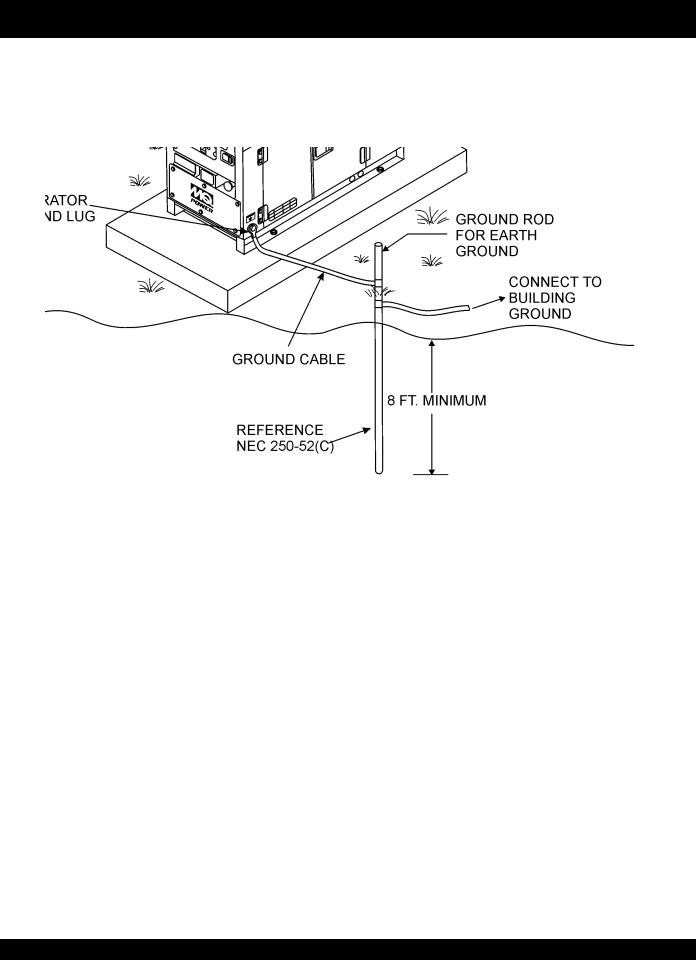
DCA-600SSK — INSTALLATION
Figure 3. Typical Generator Grounding Application
PAGE 16 — DCA-600SSK — OPERATION AND PARTS MANUAL (STD) — REV. #7 (04/30/10)
Outdoor Installation
Install the generator in a area that is free of debris, bystanders, and overhead obstructions. Make sure the generator is on secure level ground so that it cannot slide or shift around. Also install the generator in a manner so that the exhaust will not be discharged in the direction of nearby homes.
The installation site must be relatively free from moisture and dust. All electrical equipment should be protected from excessive moisture. Failure to do will result in deterioration of the insulation and will result in short circuits and grounding.
Foreign materials such as dust, sand, lint and abrasive materials have a tendency to cause excessive wear to engine and alternator parts.
CAUTION - EXHAUST HAZARD
Pay close attention to ventilation when operating the generator inside tunnels and caves. The engine exhaust contains noxious elements. Engine exhaust must be routed to a ventilated area.
Indoor Installation
Exhaust gases from diesel engines are extremely poisonous.
Whenever an engine is installed indoors the exhaust fumes must be vented to the outside.The engine should be installed at least two feet from any outside wall. Using an exhaust pipe which is too long or too small can cause excessive back pressure which will cause the engine to heat excessively and possibly burn the valves.
Mounting
The generator must be mounted on a solid foundation (such as concrete) and set firmly on the foundation to isolate vibration of the generator when it is running. The generator must set at least 6 inches above the floor or grade level (in accordance to NFPA 110, Chapter 5-4.1). DO NOT remove the metal skids on the bottom of the generator. They are to resist damage to the bottom of the generator and to maintain alignment.
DCA-600SSK — INSTALLATION
Generator Grounding
To guard against electrical shock and possible damage to the equipment, it is important to provide a good EARTH ground.
Article 250 (Grounding) of the National Electrical Code (NEC) provides guide lines for proper grounding and specifies that the cable ground shall be connected to the grounding system of the building as close to the point of cable entry as practical.
NEC articles 250-64(b) and 250-66 set the following grounding requirements:
1.Use one of the following wire types to connect the generator to earth ground.
a.Copper - 10 AWG (5.3 mm2) or larger.
b.Aluminum - 8 AWG (8.4 mm2) or larger.
2.When grounding the generator (Figure 3) connect the ground cable between the lock washer and the nut on the generator and tighten the nut fully.Connect the other end of the ground cable to earth ground.
3.NEC article 250-52(c) specifies that the earth ground rod should be buried aminimum of 8 ft. into the ground.
When connecting the generator to any buildings electrical system NOTE ALWAYS consult with a licensed
electrician.
DCA-600SSK — OPERATION AND PARTS MANUAL (STD)— REV. #7 (04/30/10) — PAGE 17

DCA-600SSK —TOWING RULES FOR SAFE OPERATION
Towing Safety Precautions
CAUTION -TOWING REGULATIONS
Check with your county or state safety towing regulations before towing your generator.
To reduce the possibility of an accident while transporting the generator on public roads, always make sure the trailer
(Figure 4) that supports the generator and the towing vehicle are in good operating condition and both units are mechanically sound.
The following list of suggestions should be used when towing your generator:
Make sure the hitch and coupling of the towing vehicle are rated equal to, or greater than the trailer "gross vehicle weight rating" (GVWR).
ALWAYS inspect the hitch and coupling for wear. NEVER tow a trailer with defective hitches, couplings, chains etc.
Check the tire air pressure on both the towing vehicle and the trailer.Also check the tire tread wear on both vehicles.
ALWAYS make sure the trailer is equipped with a "Safety Chain".
■ALWAYS attach trailer's safety chain to bumper of towing vehicle.
ALWAYS make sure the vehicle and trailer directional, backup, brake, and trailer lights are connected and working properly.
Remember the maximum speed unless otherwise posted for highway towing is 45 MPH. Recommended off-road towing is not to exceed 10 MPH or less depending on type of terrain.
Place chocked blocks underneath wheel to prevent rolling, while parked.
Place support blocks underneath the trailer's bumper to prevent tipping, while parked.
Use the trailer's hand winch to adjust the height of the trailer, then insert locking pin to lock wheel stand in place, while parked.
Avoid sudden stops and starts.This can cause skidding, or jackknifing. Smooth, gradual starts and stops will improve gas milage.
Avoid sharp turns to prevent rolling. Remove wheel stand when transporting.
DO NOT transport generator with fuel in tank.
Figure 4. Generator and Trailer
PAGE 18 — DCA-600SSK — OPERATION AND PARTS MANUAL (STD) — REV. #7 (04/30/10)

DCA-600SSK — TRAILER-SAFETY GUIDELINES
CAUTION - TRAILER INSPECTION
ALWAYS make sure the trailer is in good operating condition. Check the tires for proper inflation and wear. Also check the wheel lug nuts for proper tightness.
Explanation of Chart:
This section is intended to provide the user with trailer service and maintenance information. The service and maintenance guidelines referenced in this section apply a wide range of trailers. Remember periodic inspection of the trailer will ensure safe towing of the equipment and will prevent damage to the equipment and personal injury.
It is the purpose of this section to cover the major maintenance components of the trailer. The following trailer components will be discussed in this section:
Brakes
Tires
Lug NutTorquing
Suspension
Electrical
Brake TroubleshootingTables
Use the following definitions when reading Table 3.
1.Fuel Cell - Provides an adequate amount of fuel for the equipment in use. Fuel cells must be empty when transporting equipment.
2.Braking System - System employed in stopping the trailer. Typical braking systems are electric, surge, hydraulic, hydraulic-surge and air.
3.GVWR- Gross Vehicle Weight Rating (GVWR), is the maximum number of pounds the trailer can carry, including the fuel cell (empty).
4.Frame Length - Measurement is from the ball hitch to the rear bumper (reflector).
5.Frame Width - Measurement is from fender to fender
6.Jack Stand - Trailer support device with maximum pound requirement from the tongue of the trailer.
7.Coupler - Type of hitch used on the trailer for towing.
8.Tire Size - Indicates the diameter of the tire in inches (10,12,14, etc.), and the width in millimeters (175,185,205, etc.). The tire diameter must match the diameter of the tire rim.
9.Tire Ply - The tire ply (layers) number is rated in letters; 2-ply,4-ply,6-ply, etc.
10.Wheel Hub - The wheel hub is connected to the trailer’s axle.
11.Tire Rim - Tires mounted on a tire rim. The tire rim must match the size of the tire.
12.Lug Nuts - Used to secure the wheel to the wheel hub. Always use a torque wrench to tighten down the lug nuts. See Table 17 and Figure 67 for lug nut tightening and sequence.
13.Axle - Indicates the maximum weight the axle can support in pounds, and the diameter of the axle expressed in inches. Please note that some trailers have a double axle. This will be shown as 2-6000 lbs., meaning two axles with a total weight capacity of 6000 pounds.
14.Suspension - Protects the trailer chassis from shocks transmitted through the wheels. Types of suspension used are leaf, Q-flex, and air ride.
15.Electrical - Electrical connectors (looms) are provided with the trailer so the brake lights and turn signals can be connected to the towing vehicle.
16.Application - Indicates which units can be employed on a particular trailer.
DCA-600SSK — OPERATION AND PARTS MANUAL (STD)— REV. #7 (04/30/10) — PAGE 19

DCA-600SSK —TRAILER-SPECIFICATIONS
Table 3. Trailer Specifications
MODEL |
APPLICATION |
FUEL CELL |
BRAKE SYSTEM |
GVWR |
FRAME |
FRAME |
|
JACK |
||
|
|
|
|
|
|
LENGTH |
WIDTH |
|
STAND |
|
|
|
|
|
|
|
|
|
|
||
TRLR-10W |
SDW225, |
NO |
NO |
1,900 LBS. |
96 inches |
50 inches |
800 |
LBS. (363 Kg.) |
||
|
SGW250,TLW300 |
|
|
862 Kg. |
2.43 meters |
1.27 meters |
FULL TILT WHEEL |
|||
|
|
|
|
|
|
|
|
|
||
TRLR-10 |
DCA10, TLG12, DCA- |
NO |
NO |
1,900 LBS. |
96 inches |
50 inches |
800 |
LBS. (363 Kg.) |
||
|
15 |
|
|
862 Kg. |
2.43 meters |
1.27 meters |
FULL TILT WHEEL |
|||
|
|
|
|
|
|
|
|
|
||
TRLR-10XF |
DCA10, TLG-12, |
52 Gallons |
NO |
1,900 LBS. |
96 inches |
50 inches |
800 |
LBS. (363 Kg.) |
||
|
DCA15, TLW-300 |
197 Liters |
|
862 Kg. |
2.43 meters |
1.27 meters |
FULL TILT WHEEL |
|||
|
|
|
|
|
|
|
|
|
||
TRLR-225W |
WELDERS, |
NO |
NO |
2,200 LBS. |
85 inches |
42 inches |
800 |
LBS. (363 Kg.) |
||
|
DA7000SS |
|
|
998 Kg. |
2.43 meters |
1.06 meters |
FULL TILT WHEEL |
|||
|
|
|
|
|
|
|
|
|
|
|
|
|
|
|
|
|
W/MAST 154 in. |
55 inches |
|
|
|
TRLR-BLW400 |
BLW-400 |
NO |
ELECTRIC |
2,700 LBS. |
3.19 meters |
1.40 meters |
800 |
LBS. (363 Kg.) |
||
1,224 Kg. |
W/O 124 in. |
(78 inches TALL) |
FULL TILT WHEEL |
|||||||
|
|
|
|
|||||||
|
|
|
|
|
|
3.14 meters |
1.98 meters |
|
|
|
|
|
|
|
|
|
|
|
|
||
TRLR-50X |
DCA-25 |
NO |
NO |
2,700 LBS. |
124 inches |
55 inches |
800 |
LBS. (363 Kg.) |
||
|
|
|
|
1,224 Kg. |
3.14 meters |
1.40 meters |
FULL TILT WHEEL |
|||
|
|
|
|
|
|
|
|
|
||
TRLR-50XF |
DCA-25 |
41 Gallons |
NO |
2,700 LBS. |
124 inches |
55 inches |
800 |
LBS. (363 Kg.) |
||
|
|
155 Liters |
|
1,224 Kg. |
3.14 meters |
1.40 meters |
FULL TILT WHEEL |
|||
|
|
|
|
|
|
|
|
|||
TRLR-70W |
DCA-45, -60, 70 |
NO |
SURGE |
7,000 LBS. |
186 inches |
77 inches |
2,000 LBS. (907 Kg.) |
|||
|
|
|
|
3,175 |
Kg. |
4.72 meters |
1.95 meters |
|
FLAT PAD |
|
|
|
|
|
|
|
|
|
|||
TRLR-70X |
DCA-45, -60, 70 |
OPT |
SURGE |
7,000 LBS. |
138 inches |
66 inches |
2,000 LBS. (907 Kg.) |
|||
|
|
|
|
3,175 |
Kg. |
3.50 meters |
1.67 meters |
|
FLAT PAD |
|
|
|
|
|
|
|
|
|
|||
TRLR-70XF |
DCA-45, -60, 70 |
53 Gallons |
SURGE |
7,000 LBS |
138 inches |
66 inches |
2,000 LBS. (907 Kg.) |
|||
|
|
201 Liters |
|
3,175 |
Kg. |
3.50 meters |
1.67 meters |
|
FLAT PAD |
|
|
|
|
|
|
|
|
|
|||
TRLR-100XF |
DCA-100, 125 |
150 Gallons |
HYDRAULIC SURGE |
7,000 LBS. |
190 inches |
76 inches |
2,000 LBS. (907 Kg.) |
|||
|
|
568 Liters |
|
3,175 |
Kg. |
4.82 meters |
1.93 meters |
|
FLAT PAD |
|
|
|
|
|
|
|
|
|
|
||
TRLR-85/125 |
DCA-85, 100, 125 |
145 Gallons |
HYDRAULIC |
10,000 |
LBS. |
186 inches |
77 inches |
2,000 LBS. (907 Kg.) |
||
|
|
549 Liters |
|
4,536 |
Kg. |
4.72 meters |
1.95 meters |
|
FLAT PAD |
|
|
|
|
|
|
|
|
|
|
|
|
TRLR-150XF |
DCA-150, 180 |
200 Gallons |
HYDRAULIC SURGE |
11,160 |
LBS. |
204 inches |
84 inches |
5,000 |
LBS. (2,268 Kg.) |
|
|
|
757 Liters |
|
5,062 |
Kg. |
5.18 meters |
2.13 meters |
|
FLAT PAD |
|
|
|
|
|
|
|
|
|
|
|
|
TRLR-220XF |
DCA-220 |
250 Gallons |
HYDRAULIC SURGE |
14,000 |
LBS. |
222 inches |
83 inches |
5,000 |
LBS. (2,268 Kg.) |
|
|
|
946 Liters |
|
3,175 |
Kg. |
3.63 meters |
2.10 meters |
|
FLAT PAD |
|
|
|
|
|
|
|
|
|
|
|
|
TRLR-300XF |
DCA-300 |
250 Gallons |
HYDRAULIC SURGE |
18,000 |
LBS. |
238 inches |
83 inches |
5,000 |
LBS. (2,268 Kg.) |
|
|
|
946 Liters |
|
8,165 |
Kg. |
6.04 meters |
2.10 meters |
|
FLAT PAD |
|
|
|
|
|
|
|
|
|
|
|
|
TRLR-400XF |
DCA-400 |
350 Gallons |
ELECTRIC |
18,000 |
LBS. |
238 inches |
83 inches |
5,000 |
LBS. (2,268 Kg.) |
|
|
|
1, 324 Liters |
|
8,165 |
Kg. |
6.04 meters |
2.10 meters |
|
FLAT PAD |
|
|
|
|
|
|
|
|
|
|
||
TRLR-600XF |
DCA-600, 800 |
550 Gallons |
AIR |
30,000 LBS. |
384 inches |
96 inches |
5,000 |
LBS. (2,268 Kg.) |
||
|
|
2,082 Liters |
|
13,607 Kg. |
9.75 meters |
2.43 meters |
|
FLAT PAD |
||
|
|
|
|
|
|
|
|
|
||
TRLR-800SX |
DCA-600, 800 |
550 Gallons |
AIR |
30,000 LBS. |
384 inches |
96 inches |
5,000 |
LBS. (2,268 Kg.) |
||
|
|
2,082 Liters |
|
13,607 Kg. |
9.75 meters |
2.43 meters |
|
FLAT PAD |
||
|
|
|
|
|
|
|
|
|
|
|
PAGE 20 — DCA-600SSK — OPERATION AND PARTS MANUAL (STD) — REV. #7 (04/30/10)
DCA-600SSK —TRAILER-SPECIFICATIONS
Table 3. Specifications (Con't)
MODEL |
COUPLER |
TIRES |
WHEELS |
AXLE |
HUBS |
SUSPENSION |
ELECTRICAL |
|
|
|
|
|
|
|
|
TRLR-10W |
2" BALL CLASS |
175-13C |
13"X4.50" |
2200# 2X2 |
5 LUG |
3 LEAF |
4 WIRE LOOM W/ |
|
2 ADJUSTABLE |
|
|
|
|
|
4 POLE FLAT |
|
|
|
|
|
|
|
|
TRLR-10 |
2"BALL CLASS |
175-13C |
13"X4.5" |
2200#2X2 |
5 LUG |
3 LEAF |
4 POLE FLAT |
|
2 ADJUSTABLE |
|
|
|
|
|
|
|
|
|
|
|
|
|
|
TRLR-10XF |
2"BALL CLASS |
175-13C |
13"X4.5" |
2200#2X2 |
5 LUG |
3 LEAF |
4 POLE FLAT |
|
2 ADJUSTABLE |
|
|
|
|
|
|
|
|
|
|
|
|
|
|
TRLR-225W |
2"BALL CLASS |
175-13B |
13X4.5" |
2200#2X2 |
5 LUG |
Q FLEX |
4 POLE FLAT |
|
2 ADJUSTABLE |
|
|
|
|
|
|
|
|
|
|
|
|
|
|
TRLR-BLW 400 |
2"BALL CLASS |
175-13C |
13 X 4.5" |
2200#2X2 |
5 LUG |
3 LEAF |
4 POLE FLAT |
|
2 ADJUSTABLE |
|
|
|
|
|
|
|
|
|
|
|
|
|
|
TRLR-50X |
2" BALL CLASS |
B78-13LRC |
13"X4.50" |
3,500 lbs. |
5 LUG |
4 LEAF |
4 POLE RUBBER FLAT |
|
|
|
|
2-3/8" |
|
|
|
|
|
|
|
|
|
|
|
TRLR-50XF |
2" BALL CLASS |
B78-13LRC |
13"X4.50" |
3,500 lbs. |
5 LUG |
4 LEAF |
4 POLE RUBBER FLAT |
|
|
|
|
2-3/8" |
|
|
|
|
|
|
|
|
|
|
|
TRLR-70W |
2" BALL CLASS |
205-14C |
14"X5" |
3,500 lbs. |
5 LUG |
5 LEAF |
4 POLE RUBBER FLAT |
|
3" ADJUSTABLE |
BIAS (4) |
|
3" |
|
|
|
|
|
|
|
|
|
|
|
TRLR-70X |
2" BALL CLASS |
205-14C |
14"X5" |
3,500 lbs. |
5 LUG |
5 LEAF |
4 POLE RUBBER FLAT |
|
3" ADJUSTABLE |
BIAS (4) |
|
3" |
|
|
|
|
|
|
|
|
|
|
|
TRLR-70XF |
2" BALL CLASS |
205-14C |
14"X5" |
3,500 lbs. |
5 LUG |
5 LEAF |
4 POLE RUBBER FLAT |
|
3" ADJUSTABLE |
BIAS (4) |
|
3" |
|
|
|
|
|
|
|
|
|
|
|
TRLR-100XF |
ADJUSTABLE 2-5/6 OPT |
205-15C |
14"X5.5" |
3,500 lbs. |
5 LUG |
5 LEAF |
4 WIRE LOOM |
|
3" EYE |
BIAS (4) |
|
3" |
|
|
|
|
|
|
|
|
|
|
|
TRLR-85/125 |
ADJUSTABLE 2-5/6 OPT |
ST225/75R15D |
14"x6" |
(2)-6,000 lbs. |
6 LUG |
7 LEAF |
4 WIRE LOOM |
|
3" EYE |
RADIAL (4) |
|
|
|
|
|
|
|
|
|
|
|
|
|
TRLR-150XF |
3" BALL EYE |
750-16 E |
16"X7" |
(2)-6,000 lbs. |
8 LUG |
7 LEAF |
4 WIRE LOOM |
|
|
BIAS (4) |
|
|
|
|
|
|
|
|
|
|
|
|
|
TRLR-220XF |
3" EYE ADJUSTABLE |
ST235/85R16E |
16"X7" |
(2)-7,000 lbs. |
8 LUG |
Q FLEX |
4 WIRE LOOM |
|
|
RADIAL(4) |
|
|
|
|
|
|
|
|
|
|
|
|
|
TRLR-300XF |
3" EYE ADJUSTABLE |
ST235/85R16E |
16"X7" |
(2)-6,000 lbs. |
8 LUG |
Q FLEX |
4 WIRE LOOM |
|
|
RADIAL(6) |
|
|
|
|
|
|
|
|
|
|
|
|
|
TRLR-400XF |
3" EYE ADJUSTABLE |
ST235/85R16E |
16"X7" |
(3)-7,000 lbs. |
8 LUG |
Q FLEX |
4 WIRE LOOM |
|
|
RADIAL(6) |
|
|
|
|
|
|
|
|
|
|
|
|
|
TRLR-600XF |
5TH WHEEL |
ST215/75R17.5H |
16"X7" |
(3)-10,000 lbs. |
8 LUG |
7 LEAF |
6 WIRE LOOM |
|
|
RADIAL (8) |
|
|
|
|
|
|
|
|
|
|
|
|
|
TRLR-800AR |
5TH WHEEL |
ST215/75R17.5H |
16"X7" |
(3)-10,000 lbs. |
8 LUG |
AIR-RIDE |
6 WIRE LOOM |
|
|
RADIAL (8) |
|
|
|
|
|
|
|
|
|
|
|
|
|
DCA-600SSK — OPERATION AND PARTS MANUAL (STD)— REV. #7 (04/30/10) — PAGE 21
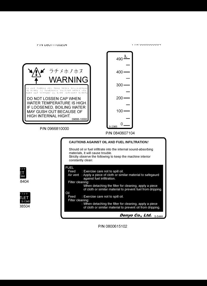
DCA-600SSK — OPERATION AND SAFETY DECALS
Machine Safety Decals
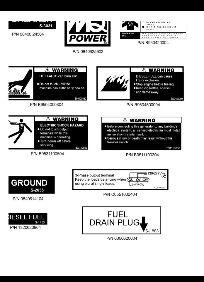
The DCA-600SSK generator is equipped with a number of safety decals. These decals are provided for operator safety and maintenance information.The illustrations below and on the preceding pages shows the decals as they appear on the machine. Should any of these decals become unreadable, replacements can be obtained from your dealer.
PAGE 22 — DCA-600SSK — OPERATION AND PARTS MANUAL (STD) — REV. #7 (04/30/10)
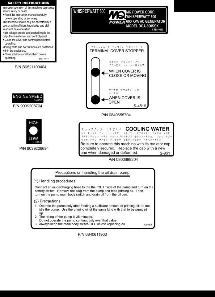
DCA-600SSK — OPERATION AND SAFETY DECALS
DCA-600SSK — OPERATION AND PARTS MANUAL (STD)— REV. #7 (04/30/10) — PAGE 23

DCA-600SSK — OPERATION AND SAFETY DECALS
PAGE 24 — DCA-600SSK — OPERATION AND PARTS MANUAL (STD) — REV. #7 (04/30/10)
DCA-600SSK — OPERATION AND SAFETY DECALS
DCA-600SSK — OPERATION AND PARTS MANUAL (STD)— REV. #7 (04/30/10) — PAGE 25

DCA-600SSK — GENERAL INFORMATION
DCA-600SSK FAMILIARIZATION
Generator
The MQ Power Model DCA-600SSK is a 528 kW generator that has been designed as a high quality portable (requires a trailer for transport) power source for telecom sites, lighting facilities, power tools, submersible pumps and other industrial and construction machinery.
Engine Control Panel
The “Engine Control Panel” is provided with the following:
Tachometer
WaterTemperature Gauge
Oil Pressure Gauge
Charging Ammeter Gauge
Engine Warning Lamp Module
Throttle Lever (Up to S/N 3698616)
Ignition Switch (Up to S/N 3698616)
Engine Speed Switch (S/N 3698617~)
Pre-Heat Button (S/N 3698617~)
Pre-Heat Lamp
Emergency Stop Button
Battery Switch
Generator Control Panel
The “Generator Control Panel” is provided with the following:
Output Voltage Adjustment Knob
Frequency Meter (Hz)
AC Ammeter (Amps)
AC Voltmeter (Volts)
Ammeter Change-Over Switch
Voltmeter Change-Over Switch
Panel Light
Panel Light Switch
MPEC Module (S/N 3698617~)
Pilot Lamp
Microprocessor Controlled Alarm System
The DCA-600SSK generator is equipped with various alarms and LED status indicators.These alarms and status indicators are provided to add safety to the generator when operating under normal conditions. The DCA-600SSK generator is designed to shutdown in the event of low oil, high coolant temperature, low battery and other operation conditions that may cause severe damage to the generator.
Open Delta Excitation System
The DCA-600SSK generator is equipped with the state of the art "Open-Delta" excitation system. The open delta system consist of an electrically independent winding wound among stationary windings of the AC output section.
There are four connections of the open delta A, B, C, and D. During steady state loads, the power from the voltage regulator is supplied from the parallel connections of A to B,
A to D, and C to D. These three phases of the voltage input to the voltage regulator are then rectified and are the excitation current for the exciter section.
When a heavy load, such as a motor starting or a short circuit occurs, the automatic voltage regulator (AVR) switches the configuration of the open delta to the series connection of B to C. This has the effect of adding the voltages of each phase to provide higher excitation to the exciter section and thus better voltage response during the application of heavy loads.
The connections of the AVR to the AC output windings are for sensing only. No power is required from these windings.
The open-delta design provides virtually unlimited excitation current, offering maximum motor starting capabilities. The excitation does not have a "fixed ceiling" and responds according the demands of the required load up to the horsepower of the engine.
Engine
The DCA-600SSK is powered by a 4 cycle, water cooled, turbocharged KOMATSU Model SA6D170AE-1 diesel engine.
This engine is designed to meet every performance requirement for the generator. Reference Table 2 for engine specifications.
In keeping with Multiquip's policy of constantly improving its products, the specifications quoted herein are subject to change without prior notice.
The basic controls and indicators for the DCA-600SSK generator are addressed on the following pages.
Electronic Governor System
The electronic governor system is made up of two parts, an electronic controller that monitors frequency variation as the load increases and decreases, and an electronic actuator that controls the engine throttle. The frequency is regulated at ±0.25 to help protect sensitive equipment.
PAGE 26 — DCA-600SSK — OPERATION AND PARTS MANUAL (STD) — REV. #7 (04/30/10)
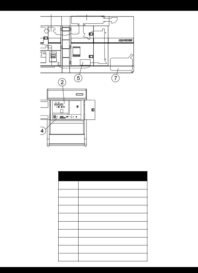
DCA-600SSK — MAJOR COMPONENTS
Table 4. Generator Major Components
ITEM NO. |
DESCRIPTION |
1 Generator Assembly
2Generator Control Panel Assembly
3Engine and Radiator Assembly
4Engine Operating Panel Assembly
5Battery Assembly
6Enclosure Assembly
7Fuel Tank Assembly
8Muffler Assembly
9Output Terminal Assembly
DCA-600SSK — OPERATION AND PARTS MANUAL (STD)— REV. #7 (04/30/10) — PAGE 27
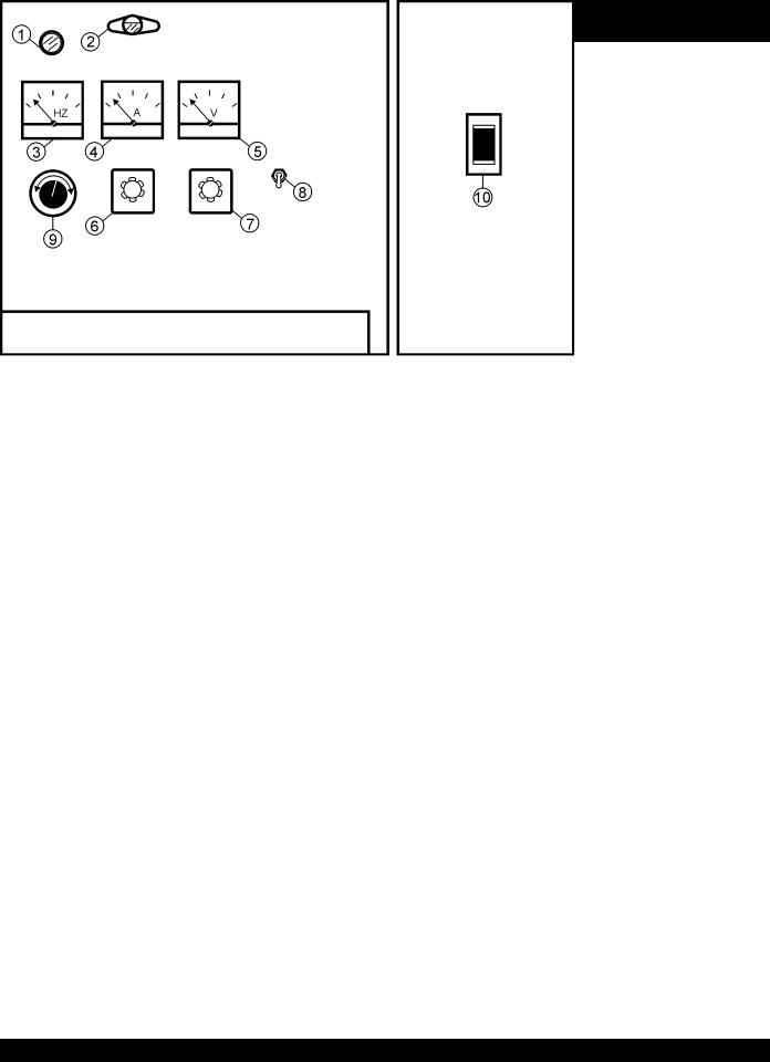
DCA-600SSK — GENERATOR CONTROL PANEL
Up to S/N 3698616
S/N 3698617~
Figure 6. Generator Control Panel
PAGE 28 — DCA-600SSK — OPERATION AND PARTS MANUAL (STD) — REV. #7 (04/30/10)

DCA-600SSK — GENERATOR CONTROL PANEL
The definitions below describe the controls and functions of the DCA-600SSK " Control Panel " (Figure 6).
1.Pilot Lamp – Indicates that the generator is working properly.
2.Panel Light – Normally used in dark areas or at night time.When activated, panel lights will illuminate.When lit this light will make it easier to read the meters and gauges. When the generator is not in use be sure to turn the panel light switch to the OFF position.
3.Frequency Meter – Indicates the output frequency in hertz (Hz). Normally 60 Hz ±1 Hz .
4.AC Ammeter – Indicates the amount of current the load is drawing from the generator.
5.AC Voltmeter – Indicates the single phase output voltage present at the UVWO terminals. .
6.Ammeter Change-Over Switch – This switch allows the AC ammeter to indicate the current flowing to the load connected to any phase of the output terminals, or to be switched off.
7.Voltmeter Change-Over Switch – This switch allows the AC voltmeter to indicate phase to phase voltage between any two phases of the output terminals or to be switched off
8.Panel Light Switch – When activated, this switch will turn on the luminate the control panel.
9.Voltage Regulator Control – Allows manual adjustment of the generator’s output voltage
10.Main Circuit Breaker – This three-pole, 1600 amp main breaker is provided to protect the UVWO voltage output terminals from overload.
11.MPEC – Microprocessor Engine Control Module –
(MPEC) has a vertical row of status LED's (inset), that when lit, indicate that an engine malfunction (fault), has been detected. When a fault has been detected the MPEC will evaluate the fault and if the fault is major will shutdown the generator.
During cranking cycle , The MPEC will attempt to crank the engine for 10 seconds before disengaging. If the engine does not engage (start) by the third attempt, the engine will be shutdown by the engine controller’s " Over Crank Protection" mode. If the engine engages at a speed (RPM's) that is not safe, the controller will shutdown the engine by initializing the "Over Speed Protection" mode.
Also the MPEC will shutdown the generator in the event of low oil pressure, high coolant temperature, low coolant level, and loss of magnetic pickup. These conditions can be observed by monitoring the LED status indicators on the front of the MPEC module.
A.Off/Manual/Auto Switch – This switch controls the running of the generator.If this switch is left in the "OFF" position, the generator will not run. When this switch is set to the manual position, the generator will start immediately.
If the generator is to be connected to a building's AC power source via a transfer switch (isolation), place the switch in the auto position. In this position the generator will monitor the AC line output from the building's power source. The generator will engage when commercial power falls below a preset level.
B.Low Oil Pressure – Indicates the engine pressure has fallen below 15 psi. The oil pressure is detected using variable resistive values from the oil pressure sending unit. This is considered a major fault and will shut down the generator.
C.High Coolant Temperature – Indicates the engine temperature has exceeded 215°F. The engine temperature is detected using variable resistive values from the temperature sending unit. This is considered a major fault and will shut down the generator.
D.Overcrank Shutdown – Indicates the unit has attempted to be started a preprogrammed number of times, and has failed to start. The number of cycles and duration are programmable.Typical programmable start settings is 3 cycles with a 10 second duration.
This is considered a major fault and will shut down the generator.
E.Overspeed Shutdown – Indicates that the engine is running at an unsafe speed.This is considered a major fault.
F.Engine Running – Indicates that engine is running at a safe operating speed.
DCA-600SSK — OPERATION AND PARTS MANUAL (STD)— REV. #7 (04/30/10) — PAGE 29
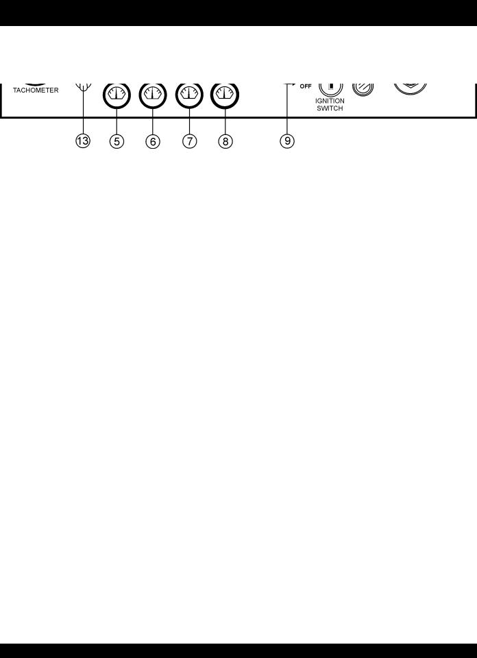
DCA-600SSK — ENGINE OPERATING PANEL
Up to S/N 3698616
S/N 3698617~
Figure 7. Engine Operating Panels
PAGE 30 — DCA-600SSK — OPERATION AND PARTS MANUAL (STD) — REV. #7 (04/30/10)
 Loading...