


 Loading...
Data/Voice/Fax Concentrator
Desktop Models: DT101, DT102, DT101/xx, DT102/xx
Rack-Mount Models: DT101R, DT102R, DT101R/xx, DT102R/xx
Owner’s Manual
Owner’s Manual
82052704 Revision E
DataTalker™ Series
Desktop Models: DT101, DT101/xx, DT102, DT102/xx
Rack-Mount Models: DT101R, DT101R/xx, DT102R, DT102R/xx
This publication may not be reproduced, in whole or in part, without prior expressed written permission from Multi-Tech Systems, Inc. All rights reserved.
Copyright © 1997, by Multi-Tech Systems, Inc.
Multi-Tech Systems, Inc. makes no representations or warranties with respect to the contents hereof and specifically disclaims any implied warranties of merchantability or fitness for any particular purpose. Furthermore, Multi-Tech Systems, Inc. reserves the right to revise this publication and to make changes from time to time in the content hereof without obligation of Multi-Tech Systems, Inc. to notify any person or organization of such revisions or changes.
|
Record of Revisions |
Revision |
Description |
E |
Manual revised to incorporate minor editorial changes. All pages at Revision E. |
(5/2/97) |
|
E |
Manual reformatted for electronic distribution. All pages remain at Revision E. |
(7/30/99) |
|
|
Patents |
This Product is covered by one or more of the following U.S. Patent Numbers: 5.301.274; 5.309.562;
5.355.365; 5.355.653; 5.452.289; 5.453.986. Other Patents Pending.
Trademarks
Trademarks of Multi-Tech Systems, Inc. are as follows: DataTalker, LANTalker, RackTalker, and the MultiTech logo.
CompuServe is a trademark of CompuServe, Inc.
Multi-Tech Systems, Inc.
2205 Woodale Drive
Mounds View, Minnesota 55112 (612) 785-3500 or (800) 328-9717 Fax (612) 785-9874
Tech Support (800) 972-2439 BBS (612) 785-3702 or (800) 392-2432
Internet Address: http://www.multitech.com

|
|
Contents |
|
Chapter 1 - Introduction and Description |
|
||
1.1 |
Introduction .................................................................................................................................... |
8 |
|
1.2 |
About This Manual......................................................................................................................... |
8 |
|
1.3 |
Product Description ..................................................................................................................... |
10 |
|
1.4 |
System Features ......................................................................................................................... |
12 |
|
|
1.4.1 |
Voice/Fax ........................................................................................................................... |
12 |
|
1.4.2 |
Data Channel ..................................................................................................................... |
12 |
|
1.4.3 |
Composite Link .................................................................................................................. |
12 |
|
1.4.4 |
Flow Control ....................................................................................................................... |
12 |
|
1.4.5 |
Parameter Memory ............................................................................................................ |
12 |
|
1.4.6 |
Diagnostics ........................................................................................................................ |
13 |
|
1.4.7 |
Operational Statistics ......................................................................................................... |
13 |
1.5 |
FCC Regulations for Telephone Line Interconnection ................................................................. |
14 |
|
1.6 |
Canadian Limitations Notice ........................................................................................................ |
15 |
|
1.7 |
Specifications .............................................................................................................................. |
16 |
|
|
1.7.1 |
Async Data Channel .......................................................................................................... |
16 |
|
1.7.2 |
Sync Data Channel ............................................................................................................ |
16 |
|
1.7.3 |
System Control (Command Port) ....................................................................................... |
16 |
|
1.7.4 |
Composite Link .................................................................................................................. |
16 |
|
1.7.5 |
Internal Modem .................................................................................................................. |
17 |
|
1.7.6 |
Internal DSU ...................................................................................................................... |
17 |
|
1.7.7 |
ISDN Terminal Adapter ...................................................................................................... |
17 |
|
1.7.8 |
Voice/Fax Channel ............................................................................................................. |
17 |
|
1.7.9 |
Electrical/Physical .............................................................................................................. |
18 |
Chapter 2 - Configuration |
|
||
2.1 |
Introduction .................................................................................................................................. |
20 |
|
2.2 |
Configuration 1 - Dial-Up Link ..................................................................................................... |
21 |
|
2.3 |
Configuration 2 - MMH900 Series with Voice/Fax ....................................................................... |
25 |
|
2.4 |
Configuration 3 - LAN to LAN ...................................................................................................... |
28 |
|
2.5 |
Configuration 4 - PBX to PBX ..................................................................................................... |
32 |
|
Chapter 3 - Front and Rear Panel Descriptions |
|
||
3.1 |
Introduction .................................................................................................................................. |
36 |
|
3.2 |
Indicators ..................................................................................................................................... |
36 |
|
3.3 |
Connectors .................................................................................................................................. |
39 |
|
|
3.3.1 |
Frame Ground Connector (GND) ...................................................................................... |
39 |
|
3.3.2 |
POWER Connector ........................................................................................................... |
39 |
|
3.3.3 |
DATA/COMMAND Connector ............................................................................................ |
39 |
|
3.3.4 |
EXTERNAL COMPOSITE RS232C/V.35 Connector ......................................................... |
39 |
|
3.3.5 |
VOICE/FAX CHANNEL 1 FXS Connector ......................................................................... |
39 |
|
3.3.6 |
VOICE/FAX CHANNEL 1 FXO Connector ......................................................................... |
39 |
|
3.3.7 |
VOICE/FAX CHANNEL 1 E&M Connector ........................................................................ |
40 |
|
3.3.8 |
DSU/TA DIGITAL Connector .............................................................................................. |
40 |
|
3.3.9 |
MODEM LEASED Connector ............................................................................................ |
40 |
|
3.3.10 |
MODEM DIAL-UP Connector ............................................................................................ |
40 |
3.4 |
Switches and Shunts ................................................................................................................... |
41 |
|
|
3.4.1 |
Front Panel Switches ......................................................................................................... |
41 |
|
3.4.2 |
Power Switch ..................................................................................................................... |
41 |
|
3.4.3 |
DIP Switch ......................................................................................................................... |
42 |
|
3.4.4 |
RS232C/V.35 Shunt ........................................................................................................... |
42 |
|
|
|
|

Chapter 4 - Unpacking and Configuration
4.1 |
Introduction .................................................................................................................................. |
44 |
4.2 |
Unpacking ................................................................................................................................... |
44 |
4.3 |
Configuration Summary ............................................................................................................... |
45 |
4.4 |
Data Port Configuration Considerations ...................................................................................... |
45 |
4.5 |
Voice/Fax Channel Configuration Considerations ....................................................................... |
46 |
4.6 |
Composite Link Configuration Considerations ............................................................................ |
47 |
4.7 |
Configuration Procedure ............................................................................................................. |
48 |
Chapter 5 - Installation
5.1 |
Introduction .................................................................................................................................. |
56 |
5.2 |
Cabling ........................................................................................................................................ |
56 |
5.3 |
V.35 Shunt ................................................................................................................................... |
60 |
5.4 |
Power-On and Checkout ............................................................................................................. |
61 |
Chapter 6 - Menus
6.1 |
Introduction .................................................................................................................................. |
66 |
|
6.2 |
Configurations Menu ................................................................................................................... |
66 |
|
|
6.2.1 |
Data Port Configuration ..................................................................................................... |
67 |
|
6.2.2 |
Sync Data Port Configuration ............................................................................................ |
69 |
|
6.2.3 |
Voice/Fax Channel Configuration ...................................................................................... |
70 |
|
6.2.4 |
Composite Link Configuration ............................................................................................ |
73 |
6.3 |
Statistics ...................................................................................................................................... |
78 |
|
6.4 |
Reset Options .............................................................................................................................. |
79 |
|
6.5 |
Diagnostic Tests .......................................................................................................................... |
79 |
|
|
6.5.1 |
Loop Tests ......................................................................................................................... |
80 |
6.6 |
Configure Remote Unit ................................................................................................................ |
81 |
|
|
6.6.1 |
MMV8/16/32 Configuration Options ................................................................................... |
81 |
|
6.6.2 |
Quick Setup ....................................................................................................................... |
82 |
Chapter 7 - Troubleshooting
7.1 |
Introduction .................................................................................................................................. |
88 |
7.2 |
Importance of the Composite Link Statistics Report .................................................................... |
88 |
7.3 |
Test Cables .................................................................................................................................. |
89 |
7.4 |
Troubleshooting Guide ................................................................................................................ |
90 |
7.5 |
Composite Link Settings - Internal DSU ...................................................................................... |
99 |
7.6 |
Composite Link Settings - Internal ISDN Terminal .......................................................................... |
|
|
Adapter ...................................................................................................................................... |
100 |
7.7 |
Composite Link Settings - Internal Modem ................................................................................ |
101 |
7.8 |
Composite Link Settings - External Device ............................................................................... |
102 |
7.9 |
Composite Link Statistics .......................................................................................................... |
103 |
7.10 |
Data Port Configuration ............................................................................................................. |
105 |
7.11 |
Voice/Fax Channel Configuration .............................................................................................. |
107 |
7.12 |
Diagnostic Testing ..................................................................................................................... |
109 |
Chapter 8 - Warranty, Service and Tech Support
8.1 |
Introduction ................................................................................................................................. |
112 |
|
8.2 |
Limited Warranty ........................................................................................................................ |
112 |
|
|
8.2.1 |
On-line Warranty Registration........................................................................................... |
112 |
8.3 |
Tech Support .............................................................................................................................. |
113 |
|
|
8.3.1 |
Recording DataTalker Information .................................................................................... |
113 |
|
8.3.2 |
Service .............................................................................................................................. |
113 |
8.4 |
The Multi-Tech BBS .................................................................................................................... |
114 |
|
8.5 |
About the Internet ....................................................................................................................... |
115 |
|
|
|
|
|

Appendixes |
|
Appendix A - ASCII Conversion Chart ..................................................................................................... |
118 |
Appendix B - RS-232C Interface Specification ........................................................................................ |
119 |
Appendix C - Cabling Diagrams ............................................................................................................. |
120 |
Appendix D - Flow Control Background ................................................................................................. |
124 |
Appendix E - MMH2834 Modem S-Registers ........................................................................................ |
125 |
Appendix F - MMH2834 Modem Commands ......................................................................................... |
127 |
Glossary |
|
Index |
|

Chapter 1 - Introduction and Description
DataTalker Owner’s Manual
1.1 Introduction
Congratulations! Your new Multi-Tech DataTalker™ is one of the finest data/voice/fax concentrators on the market today. The DataTalker optimizes wide area network (WAN) links by simultaneously transmitting voice and/or fax with LAN or computer data over a single phone line, digital service, or ISDN service.
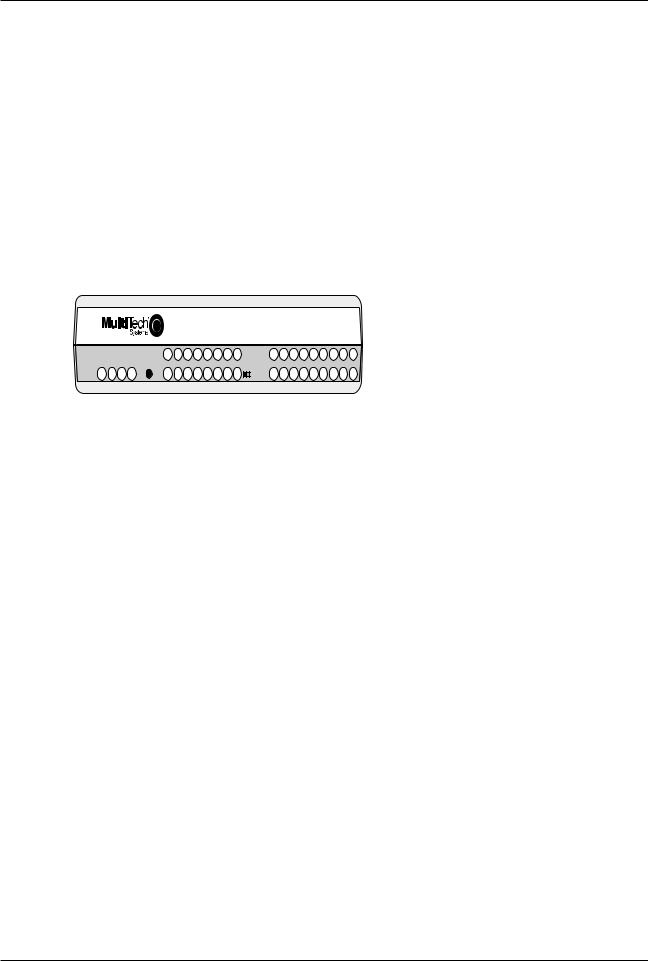
The DataTalker basic model (DT101) supports one asynchronous or synchronous input data channel, one voice/fax channel, and a synchronous external composite link. Options include a second voice/fax channel (DT102) and an internal composite link modem (DT101/V34 or DT102/ V34), DSU (DT101/56 or DT102/56), or ISDN terminal adapter (DT101/IS or DT102/IS). It comes in two basic versions: a desktop version for home offices and a rack-mount version for central office applications (DT101R and DT102R models). The DataTalker is software driven using configuration menus, and is controlled by you through its command port for great flexibility and ease of operation. This Owner’s Manual will help you to install and use your DataTalker, and also serve as a valuable information resource in the future.
|
|
|
|
|
|
|
|
|
|
|
MultiMux101 |
|
|
|
|
|||||
|
|
|
|
|
|
|
|
|
|
|
Data / Voice / Fax Concentrator |
|
|
|
||||||
|
|
VOICE / |
FXS |
FXO |
E&M |
FAX |
XMT |
RCV |
XSG |
RSG |
RXT |
FCR |
RD |
TM |
V35 |
EXT |
MDM |
DSU |
TA |
|
|
|
FAX 2 |
|
|
|
|
|
|
|
|
COMPOSITE |
|
|
|
|
|
|
|
|
|
|
|
|
|
|
|
|
|
|
|
|
LINK |
|
|
|
28.8 |
DTR |
DBUP |
OH |
|
|
DATA/ |
|
VOICE / |
|
|
|
|
|
|
|
|
STATUS |
|
|
|
|
|
|
|
|
|
XMT RCV FC COM ORIG |
FXS |
FXO |
E&M |
FAX |
XMT |
RCV |
XSG |
RSG |
CD |
RCV |
XMT |
CTS |
56 |
RTS |
NS |
OOS |
2B |
|||
COMMAND |
FAX 1 |
|||||||||||||||||||
|
|
|
|
|
|
|
|
|
|
101 |
MDM / TA |
|
|
|
|
|
|
|
|
|
Figure 1-1. DataTalker (Desktop Version)
1.2 About This Manual
This manual has eight chapters. There are also several appendices at the end of the manual, most of which summarize information contained in the chapters. These appendices can be used as quick references. The information contained in each chapter is as follows:
Chapter 1 - Introduction
This chapter is an introduction to the world of multiplexing. If you already have an extensive background in multiplexing, this introduction will provide a good review.
Chapter 2 - Configuration Examples
This chapter describes DataTalker configurations and provides examples of how the DataTalker is typically used. The basic model has a synchronous or asynchronous data channel, a voice/fax channel, and a composite link supporting synchronous communications. Options include a second voice/fax channel and an internal V.34 (33.6K bps) modem, 56K bps DSU, or ISDN terminal adapter.
Chapter 3 - Front and Back Panel Descriptions
Chapter 3 describes the front panel indicators, back panel connections, and switches. The front panel indicators are grouped into data and command port, voice/fax channels, and composite link status. The back panel provides all cable connections.
8

Chapter 1 - Introduction and Description
Chapter 4 - Unpacking and Configuration
This chapter describes the contents of the shipping container; provides a customizeable configuration summary; discusses configuration considerations for the data port, voice/fax channel, and the composite link; and provides a detailed configuration procedure. The configuration procedure simplifies the process by asking questions about your application, which allows you to glide through the configuration process by configuring only the items that need to be changed.
Chapter 5 - Installation
Chapter 5 provides procedures for cabling your DataTalker, moving the V.35 shunt, applying power, and checking it out. Cabling involves a minimum of three cables. Each cable connection is explained in detail. If a V.35 interface is used, a procedure on how to move the shunt is provided. Finally, a power-on and checkout procedure is provided with some suggestions on what to do in case something goes wrong.
Chapter 6 - Menus
The DataTalker is software driven using menus, and is controlled through a command port device. This chapter describes the menus and the impact each option has on your system’s operation.
Chapter 7 - Troubleshooting
This chapter is a guide to troubleshooting your DataTalker. It contains lists of error conditions, probable causes, and suggested fixes or steps designed to isolate the failing unit in your communications network.
Chapter 8 - Service, Warranty and Tech Support
Chapter 8 provides instructions on getting service for the DataTalker at the factory; a statement of the limited warranty; information about our user bulletin board service, and space for recording information about your DataTalker prior to calling Multi-Tech's Technical Support.
9
DataTalker Owner’s Manual
1.3 Product Description
The DataTalker series of multiplexers has a single synchronous or asynchronous data channel, a command port, one or two voice/fax channels, and a single synchronous composite link with an internal data service unit (DSU), modem, ISDN terminal adapter, or an external synchronous link device. The DataTalker can be connected to an asynchronous device such as a PC or host computer, an external synchronous device such as a LAN router, or the composite link of an MMH900 series MultiMux. It also can be connected to telephone equipment for voice or fax traffic over your standard composite link. The DataTalker’s data port allows either synchronous or asynchronous devices to be connected to it. The command port allows you to configure your data channel, composite link, and voice mode of operation. The composite link can be configured for an internal 28.8K bps dial-up/leased line modem, an internal DSU for digital communications over a digital data service (DDS) network, or an ISDN terminal adapter for Basic Rate Interface Service. It can also be configured for external synchronous link devices. The voice/fax channel supports phone, fax, or key telephone system equipment through an FXS interface, a PBX station-side connection through an FXO interface, or a PBX trunk connection through an E&M interface. The DT101/V34 and DT102/V34 DataTalkers are dual-function models. If the user requires traditional data communications, these models provide a simple switch to enable a standalone V.34 modem mode, which supports dial-in/dial-out data communications for Internet, BBS, and other on-line access.
EPROM
AT Commands
|
|
|
Configurations |
|
|
C |
|
Composite |
||
|
|
|
|
|
o |
|
||||
|
|
|
|
|
|
|
|
|
Link |
|
|
|
|
|
|
|
|
Modem, |
m |
L |
|
|
|
|
|
|
|
Serial |
|
|||
|
|
Data/ |
|
Data/Command |
DSU, or |
p |
i |
PDN |
||
|
|
Command |
I/O |
|
Processor |
Communications |
Terminal |
o |
n |
|
|
|
Channel |
|
|
|
Controller |
Adapter |
s |
k |
|
|
|
|
|
|
|
|
i |
|
||
|
|
|
|
|
|
|
|
|
|
|
|
|
|
|
|
|
|
|
t |
|
|
|
|
|
|
|
|
|
|
e |
|
|
|
|
|
|
|
RAM |
|
|
|
|
|
|
Trunk |
E&M |
|
|
|
Port |
|
|
|
|
PSTN |
|
|
Analog |
RAM |
|
|
|
|
||
Trunk |
|
|
|
|
|
|
||||
|
|
Channel 1 |
|
|
|
|
|
|||
|
Trunk |
|
|
to |
Digitize |
|
|
|
|
|
|
Station |
|
|
CODEC |
Digital |
|
|
|
|
|
|
Station |
|
|
A to D |
Digital |
Voice/fax |
|
|
|
|
|
FXO |
|
|
|
|
|
|
|||
|
|
|
D to A |
Signal |
RAM |
|
|
|
|
|
|
PBX |
|
|
Processor |
|
|
|
|
||
|
|
|
|
Digital |
|
|
|
|
|
|
|
|
|
|
|
EPROM |
|
|
|
|
|
|
|
|
|
|
to |
|
|
|
|
|
|
|
FXS |
|
|
Analog |
|
|
|
|
|
|
|
|
|
|
|
|
|
|
|
|
Fax/Telephone
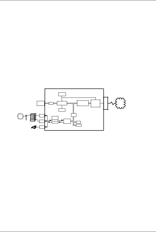
Figure 1-2. Block Diagram
A simplified block diagram of the DataTalker is shown in Figure 1-2. The data channel on the top left and the voice/fax channel on the bottom left feed data to a serial communications controller that provides the path through a modem, DSU, or ISDN terminal adapter to the public data network. The data channel, voice/fax channel, and the serial communications controller are on the main printed circuit board. The internal modem, DSU, or terminal adapter is a daughter board that plugs into the main board. The data/command channel is a dual purpose channel to which a synchronous or asynchronous device can be connected when it is used in its data mode. The voice/fax channel allows you to connect a telephone, a PBX (Private Branch eXchange) extension, or a PBX E&M trunk for voice or fax communication. On the other end of the DataTalker, an internal 33.6K bps modem, 56K bps DSU, or ISDN terminal adapter provides the composite link interface to the public data network.
The data/command channel can have a terminal or PC connected to it for configuring the DataTalker. The versatility of the data/command port allows the DataTalker to be connected to a synchronous or asynchronous device in the data mode or to an asynchronous device in the command mode when the DataTalker needs to have the configuration of the data channel, voice/ fax channel, or the composite link changed. The data/command channel can be switched between data and command modes by setting a DIP switch. If the data/command channel is in data mode, it is also possible to switch to command mode by entering the escape command
+++AT<CR>.
Before you can transfer data over the channel, you must connect a terminal or PC running
10
Chapter 1 - Introduction and Description
communications software to the DATA/COMMAND connector on the back panel and configure the data channel for the type of data that is going to be transferred. For example, if an asynchronous device is going to be connected to the data channel, you must set the speed of the channel, the word length, the number of stop bits, whether or not you are going to have parity checking, the flow control type, and other aspects of asynchronous data. After you have configured the data channel, remove the command port device and connect the data channel device, allowing data to be transferred from the asynchronous device to the MultiMux’s input/ output circuitry.
To operate the data channel in synchronous mode, as when connecting to a remote LAN bridge or to the composite link of an MMH900 series MultiMux, use the same DATA/COMMAND connector. The sync device you connect to the data channel must be an SLDC or HDLC device. Configure the data channel for sync channel operation with any SLDC/HDLC protocol , for internal or external clocking, and for speed. Configuration information is stored in non-volatile memory, which informs the data/command processor how data is received from the input/output (I/O) circuitry.
To set up the DataTalker for voice or fax operation, connect the VOICE/FAX CHANNEL 1 FXS connector on the back panel to a telephone or fax machine, connect the FXO connector to a PBX station circuit, or connect the E&M connector to a PBX E&M trunk. The FXS (Foreign eXchange Station) circuitry in the DataTalker allows a telephone or fax machine to be directly connected to the DataTalker. This circuitry provides a ringing voltage to the remote instrument when it detects an off-hook condition from the attached device, so that when two telephones are used, picking up one of the handsets rings the telephone at the other end. If the FXO (Foreign eXchange Office) connection is used at one end of the network and a telephone set is used at the other end of the network, the PBX provides the dial tone, and the remote user can dial a number as if locally attached to the PBX. The E&M connector is used to link two PBXs.
Before a voice or fax operation can take place, the DataTalker must be configured for the types of local and remote connections and for the line conditioning for the voice circuitry. The voice/fax channel is configured in the same way as the data channel: by connecting a command port device to the DATA/COMMAND connector on the back panel and setting the voice/fax configurations. Once the channel is configured, the analog to digital conversion circuitry accepts the incoming analog signal and converts it to a digital representation of the signal. The digitized signal is stored in the dual-port RAM for transmission to the serial communications controller when it requests the dual-port RAM for data. The serial communications controller conditions the digitized voice or fax data for transmission to the composite link.
In order to transfer data from the serial communications controller over the composite link to the remote site, the composite link must be configured. Factors to be considered include whether an external device or an internal modem, DSU, or terminal adapter or installed, the speed of the link, who is providing the clocking, and other link conditioning factors. The composite link is configured using a command port device and menus the same way we configured the data and voice/fax channels. This is accomplished by setting the link configurations to match the link device installed in the DataTalker and the requirements of the link service and remote system. If, for example, an internal DSU is installed that will be connected to a DDS network that provides clocking, the DataTalker detects that the link device is an internal DSU. Through the configuration stored in nonvolatile memory, it knows that the clocking is going to be provided by the DDS network. When you look at the versatility of the composite link, many other factors must be considered, such as answer or originate, twoor four-wire, and dial-up or leased line operation. But all these considerations are handled in the same manner as the example of the DSU above.
This is basically how your DataTalker is connected to a data device and voice or fax equipment, how the internal logic is conditioned to transfer data, and how the composite link passes that data on to the remote site.
11

DataTalker Owner’s Manual
1.4 System Features
1.4.1Voice/Fax
The voice/fax feature of the DataTalker allows you to establish voice or fax traffic on top of your normal data communications over a composite link, saving the expense of extra communications lines. The DataTalker provides three types of telephone circuits (FXS, FXO, and E&M) that allow a telephone, a fax machine, a PBX station card, or a PBX E&M trunk to be directly connected to it. In one configuration, these telephone circuits cause the telephone at a remote location to ring when you pick up the handset on the local telephone. In another configuration, an off-site extension moves your office extension to a remote location. In a third configuration, you can use the DataTalker to tie two PBXes together.
1.4.2Data Channel
The DataTalker data channel is able to accommodate any asynchronous device or any SDLC/ HDLC synchronous device. Configuration of the data channel is controlled by menus that determine the mode of operation (sync or async), whether or not clocking is necessary, the speed of the channel, and a number of async channel conditioning parameters.
1.4.3Composite Link
The DataTalker’s composite link is capable of synchronous and full duplex communications with an internal or external link device. Using an internal modem, ISDN terminal adapter, DSU, or external device, the DataTalker can be connected to different types of communications links, such as a dial-up line, a leased line, a Basic Rate Interface (BRI) ISDN service, or a DDS network. If an external link device is used, the DataTalker can communicate with it using either the RS232 or V.35 standard.
1.4.4Flow Control
Flow control regulates the volume of data entering the data port. When the channel buffer is almost full, a flow control command is issued which tells the device attached to the data port to stop sending data. The devices on both ends of the link must be configured for the same flow control method. The most common flow control methods are XON/XOFF and RS232C signal control (using CTS). The DataTalker supports these and ENQ/ACK.
DATATALKER-INITIATED |
|
CHANNEL DEVICE- |
||||||
FLOW CONTROL |
|
INITIATED PACING |
||||||
|
DATA |
|
|
|
DATA |
|
||
Channel |
|
|
DataTalker |
|
Channel |
|
|
DataTalker |
|
|
|
|
|
||||
Device |
|
|
|
Device |
|
|
||
|
|
|
|
|
|
|
||
|
|
|
|
|
|
|
|
|
Flow control stops the input of data to the DataTalker
Pacing stops the output of data from the DataTalker
1.4.5Parameter Memory
A nonvolatile memory for storing configurations and options means that the DataTalker remains configured until you change it. You can configure a DataTalker and save the parameters to memory, turn it off, ship it, and use it without having to reconfigure it.
12

Chapter 1 - Introduction and Description
1.4.6Diagnostics
Diagnostics in a network are of considerable importance. That is why the DataTalker is equipped with several diagnostic modes that will test every aspect of the network. The diagnostics include easy-to-execute tests for the data channel, voice/fax channel, composite link, and various components of the DataTalker unit itself. The diagnostic tests are executed from a single diagnostic tests menu by selecting the test number and following any corresponding instructions given by the DataTalker.
1.4.7Operational Statistics
Operational statistics provide an activity report of the DataTalker network. Statistics such as receive-block errors pinpoint composite link device or line problems. Composite link statistics are displayed in a single screen.
13

DataTalker Owner’s Manual
1.5FCC Regulations for Telephone Line Interconnection
1.This equipment complies with Part 68 of the FCC rules. On the outside surface of this equipment is a label that contains, among other information, the FCC registration number and ringer equivalence number (REN). If requested, this information must be provided to the telephone company.
2.As indicated below the suitable jack (USOC connecting arrangement) for this equipment is shown. If applicable, the facility interface codes (FIC) and service order codes (SOC) are shown.
3.The ringer equivalence number (REN) is used to determine the quantity of devices which may be connected to the telephone line. Excessive RENs on the telephone line may result in the devices not ringing in response to an incoming call. In most, but not all areas, the sum of the RENs should not exceed five (5.0). To be certain of the number of devices that may be connected to the line, as determined by the total RENs, contact the telephone company to determine the maximum REN for the calling area.
4.If this equipment causes harm to the telephone network, the telephone company will notify you in advance. But if advance notice isn’t practical, the telephone company will notify the customer as soon as possible. Also, you will be advised of your right to file a complaint with the FCC if you believe it is necessary.
5.The telephone company may make changes in its facilities, equipment, operations, or procedures that could affect the operation of the equipment. If this happens, the telephone company will provide advance notice in order for you to make necessary modifications in order to maintain uninterrupted service.
6.If trouble is experienced with this equipment (the model of which is indicated below) please contact Multi-Tech Systems, Inc. at the address shown below for details of how to have repairs made. If the trouble is causing harm to the telephone network, the telephone company may request you remove the equipment from the network until the problem is resolved.
7.No repairs are to be made by you. Repairs are to be made only by Multi-Tech Systems or its licensees. Unauthorized repairs void registration and warranty.
8.This equipment cannot be used on public coin service provided by the telephone company. Connection to Party Line Service is subject to state tariffs. (Contact the state public utility commission, public service commission or corporation commission for information.)
9.If so required, this equipment is hearing aid compatible.
Manufacturer: |
Multi-Tech Systems, Inc. |
Model Number: |
DT10x and DT10xR Series |
FCC Registration Number: |
AU7USA-22313-DE-N (DSU) |
|
AU7USA-22271-MM-E (Modem) |
Ringer Equivalence: |
0.3B (Modem) |
Modular Jack (USOC): |
RJ-11 or RJ-48 (single line) |
Service Center in U.S.A. |
Multi-Tech Systems Inc. |
|
2205 Woodale Drive |
|
Mounds View, MN 55112 USA |
|
(612) 785-3500 or (800) 328-9717 |
|
Fax (612) 785-9874 |
14

Chapter 1 - Introduction and Description
1.6 Canadian Limitations Notice
Notice: The Canadian Department of Communications label identifies certificated equipment. This certification means that the equipment meets certain telecommunications network protective, operational and safety requirements. The department does not guarantee the equipment will operate to the user’s satisfaction.
Before installing this equipment, users should ensure that it is permissible to be connected to the facilities of the local telecommunications company. The equipment must also be installed using an acceptable method of connection. In some cases, the company’s inside wiring associated with a single line individual service may be extended by means of a certified connector assembly (telephone extension cord). The customer should be aware that compliance with the above conditions may not prevent degradation of service in some situations.
Repairs to certified equipment should be made by an authorized Canadian facility designated by the Supplier. Any repairs or alterations made by the user to this equipment; or equipment malfunctions, may give the telecommunications company cause to request the user to disconnect the equipment.
Users should insure for their own protection that the electrical ground connections of the power utility, telephone lines and internal metallic water pipe system, if present, are connected together. This precaution may be particularly important in rural areas.
Caution: Users should not attempt to make such connections themselves, but should contact the appropriate electric inspection authority, or electrician, as appropriate.
The Load Number (LN) assigned to each terminal device denotes the percentage of the total load to be connected to a telephone loop which is used by the device, to prevent overloading. The termination on a loop may consist of any combinations of devices subject only to the requirement that the total of the Load Numbers of all the devices does not exceed 100.
The load number for the composite link modem is 4.
15

DataTalker Owner’s Manual
1.7 Specifications
1.7.1Async Data Channel
Number of Channels |
One |
Maximum Speed |
115,200 bps |
Channel Speed |
All standard speeds from 300 bps to 115,200 bps |
Data Format |
5, 6, 7, or 8 data bits, with 1, 1.5, or 2 stop bits |
Parity |
Odd, even, or none |
Local Echo |
On or off selectable |
Flow Control |
XON/XOFF, CTS, or HP ENQ/ACK selectable |
Pacing |
On or off selectable, RTS on/off, or XON/XOFF |
Interface |
RS-232D/ITU-T V.24; DB-25 female connector |
1.7.2Sync Data Channel
Data Format |
Synchronous |
Channel Speed |
Up to 128K bps |
Protocol |
SDLC/HDLC |
Error Correction |
16-bit CRC block check with ARQ |
Interface |
RS-232D/ITU-T V.24; DB-25 female connector |
1.7.3System Control (Command Port)
Local Access |
Through DataTalker’s RS232C command port |
Device |
Any asynchronous keyboard terminal or PC in terminal mode (local |
|
access only) |
Menus |
Menus to configure data channel, voice/fax channel(s), and |
|
composite link. Statistics menu and test menus are provided to |
|
monitor performance and diagnose problems. |
Diagnostics |
Data or voice loopback, memory, watch dog tests, and DIP switch |
|
definitions and settings |
1.7.4Composite Link
Number of Links |
One |
Data Format |
Synchronous |
Link Speeds |
Up to 256K bps |
Link Protocol |
Proprietary modified HDLC |
Error Correction |
16-bit CRC block check with ARQ |
Interface |
RS-232D/V.24 or ITU-T V.35, or use DataTalker integral modem, |
|
DSU, or ISDN terminal adapter |
16

Chapter 1 - Introduction and Description
1.7.5Internal Modem
Modulation |
ITU-T V.34; AT&T V.32 terbo; ITU-T V.32bis, V.32, V.22bis, V.22; Bell |
|
212A and 103 (North America) or V.23 and V.21 (international) |
Speeds |
300 bps to 33.6K bps |
Commands |
Fully AT command compatible |
Usage |
Synchronous full duplex over unconditioned 2-wire or 4-wire leased |
|
line; asynchronous half or full duplex over 2-wire dial-up |
Line Interface |
RJ-11C jack for dial-up and 2-wire or 4-wire leased line; in Canada, |
|
one CA02B connector |
1.7.6Internal DSU
Speed |
56K, 19.2K, 9.6K, 4.8K, or 2.4K bps |
Format |
Synchronous DDS or compatible |
Usage |
Full duplex over LADS (Local Area Data Set) or two-pair non-loaded |
|
metallic wire |
Line Interface |
DDS interface with an RJ-48 keyed jack |
1.7.7ISDN Terminal Adapter
Description |
Integral ISDN terminal adapter card |
Operating Mode |
ISDN Basic Rate; 1B+D or 2B+D |
Synchronous Data Rates |
2.4–128 Kbps |
Clocking |
Normal network clock (slaved to network receive clock); private |
|
network master (internal); external clock of DTE data |
Commands |
Menu system |
D-Channel Switch |
AT&T 5ESS® , 5E6; NT DMS-100™, BCS-32; |
Compatibility |
Siemens Stromberg-Carlson EWSD® , National ISDN-1;NEC |
|
International Switch |
Line Interface |
2-wire ISDN Basic Rate 2B1Q U-interface; ANSI T1.601-1992 |
|
compliant; RJ-48 jack |
B-Channel Aggregation |
BONDING Protocol, Mode 1 |
1.7.8Voice/Fax Channel
Number of Channels |
One or two channels |
Voice Digitization Rates |
9600 and 16K bps |
Automatic Fax |
Group 3 fax rates |
Modulation/Demodulation |
(2400, 4800, 7200 and 9600 bps) |
Analog Interfaces |
FXS, FXO, and E&M (channel 1 only) |
Signaling |
DTMF |
Line Interface |
FXS and FXO: RJ-11 jacks |
|
E&M: RJ-48 jack |
17

DataTalker Owner’s Manual
1.7.9Electrical/Physical
Desktop Models: |
|
Power Supply Input |
100 to 250 VAC |
Power Supply Output |
+5v@5A, +12v@1A, -12v@0.5A |
Power Consumption |
20 watts |
Dimensions |
2.3" high x 9" wide x 12.8" deep |
|
5.7 cm high x 22.9 cm wide x 32.7 cm deep |
Weight |
7 pounds (3.2 kg) |
Rack-mount Models: |
|
Power Supply Input |
100 to 250 VAC |
Frequency |
47 to 63 Hz |
Power Consumption |
20 watts |
Dimensions |
2.00" high x 9. 98" wide x 12.75" deep |
|
5.1 cm high x 25.2 cm wide x 32.4 cm deep |
Weight |
5 pounds (2.3 kg) |
18

Chapter 2 - Configuration

DataTalker Owner’s Manual
2.1 Introduction
The Multi-Tech DataTalker is available in both desktop (DT10x) and rack-mount (DT10xR) versions. The desktop version is designed for home office applications. It is mounted in a horizontal cabinet and has an external power supply, a power switch, an originate switch, and a switch that allows you to use it also as a stand-alone modem or terminal adapter. The rack-mount version is designed for main office applications. It is mounted for vertical insertion into a MultiTech RackTalker rack, has an internal power supply, is hot-swappable, and has a reset switch. Otherwise, they are identical. DataTalkers are available with a synchronous or asynchronous data channel, one or two voice/fax channels, and an optional internal composite link V.34 modem, 56K bps DSU, or 2B+D link ISDN terminal adapter.
DataTalker Configurations
Desktop Models:
|
Base Model with... |
|
1 Data Channel & 1 |
1 Data Channel & 2 |
|
|
|
Voice/Fax Channel |
Voice/Fax Channels |
|
|
|
|
|
|
||
|
No Additional Options |
DT101 |
DT102 |
||
|
Installed |
|
|||
|
|
|
|
|
|
|
|
|
|
|
|
|
33.6K bps Modem |
|
DT101/V34 |
DT102/V34 |
|
|
|
|
|
|
|
|
56K bps DSU |
|
DT101/56 |
DT102/56 |
|
|
|
|
|
|
|
|
2B+D ISDN Terminal |
DT101/IS |
DT102/IS |
|
|
|
Adapter |
|
|
||
|
|
|
|
|
|
Rack-Mount Models: |
|
|
|
|
|
|
|
|
|
|
|
|
Base Model with... |
|
1 Data Channel & 1 |
1 Data Channel & 2 |
|
|
|
Voice/Fax Channel |
Voice/Fax Channels |
|
|
|
|
|
|
||
|
No Additional Options |
DT101R |
DT102R |
||
|
Installed |
|
|||
|
|
|
|
|
|
|
|
|
|
|
|
|
33.6K bps Modem |
|
DT101R/V34 |
DT102R/V34 |
|
|
|
|
|
|
|
|
56K bps DSU |
|
DT101R/56 |
DT102R/56 |
|
|
|
|
|
|
|
|
2B+D ISDN Terminal |
DT101R/IS |
DT102R/IS |
|
|
|
Adapter |
|
|
||
|
|
|
|
|
|
Valid Voice/Fax Configurations: |
|
|
|||
Configuration |
Description |
|
|
||
E&M to E&M |
Any phone or fax machine connected to the PBX at one site can call |
||||
|
|
any phone or fax machine connected to the PBX at the other end. |
|||
FXS to FXS |
No number must be dialed. If the phone or fax machine on one end |
||||
|
|
goes off hook, the phone or fax machine on the other end rings. |
|||
FXS to FXO |
The phone and fax machine at the FXS site act as though they are |
||||
|
|
extensions of the PBX at the FXO site. |
|||
20
Chapter 2 - Configuration
2.2 Configuration 1 - Dial-Up Link
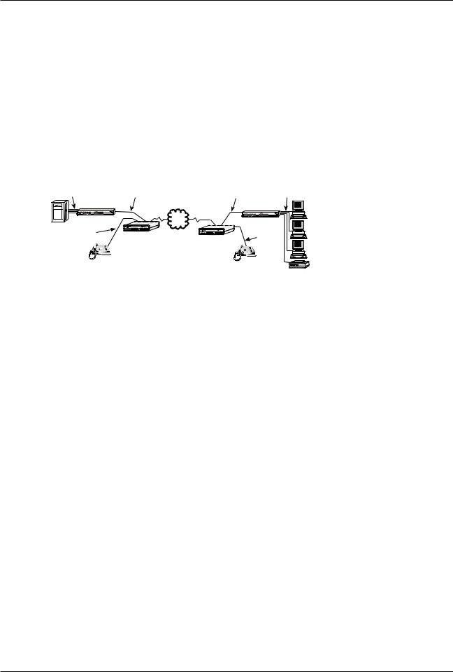
Configuration 1 is a dial-up link using a pair of DataTalkers to provide data communications between a home office PC and the main office host computer and telephone services through the main office telephone system. The data and telephone services are provided using a single line between the home office and the main office. In this application, the main office DataTalker is tied to a host computer via an async channel, and the data channel of the home office DataTalker is connected to the serial port of the home office PC. The composite link is provided by internal 33.6K modems in a dial-up configuration. All of the telephone services of the main office are supplied to the home office as if the home office was directly connected to the main office telephone system.
Asynchronous
Channel
|
|
Composite Link |
|
Asynchronous |
|
|
|
|
Channel |
|
|
PSTN |
|
|
|
Voice/Fax |
DataTalker |
|
|
|
Channel |
DataTalker |
|
|
|
|
|
PC |
|
|
|
|
|
|
PSTN |
Trunk |
|
Voice/Fax |
|
Trunk |
|
|
||
|
Channel |
|
||
|
Trunk |
|
|
|
|
|
|
|
|
|
Station |
|
|
Telephone |
|
Station |
Telephone |
|
|
|
|
|
||
|
|
|
|
PBX
Home Office
Figure 2-1 Dial-Up Link
To set up this configuration, connect the main office DataTalker to the host computer, to the inoffice telephone system (PBX), and to the public switched telephone network (PSTN). Connect the home office DataTalker to the serial port of your PC, to a telephone set, and to your local telephone line. You must also connect a terminal or a PC running communications software (such as Multi-Tech’s MultiExpress™ for DOS) to the dual function data/command port and configure the DataTalkers. Configure the DataTalker for the main office application; i.e., set up the voice/fax channel for a local interface of FXO and a remote interface of FXS. Configure the home office unit for DTR dialing of the main office DataTalker, a local interface of FXS, and a remote interface of FXO.
You must configure the DataTalkers before you connect them to the computers. To configure a DataTalker, place DIP switch position 3 in the down (closed) position and connect a command port device such as a terminal or a PC to the DATA/COMMAND connector on the back of the DataTalker. Turn on the DataTalker and PC and run your communications software in terminal mode. (Set it for direct connection at a serial port speed of 19,200 bps or slower.) Press the ENTER key to establish communications with DataTalker and see the Main Menu.
A series of configuration menus provides simple and complete configuration information for each aspect of the DataTalker. Using the menus, we will configure one DataTalker for the main office and the second one for the home office.
The menus flow from the Main Menu through the Configurations menu to configuration menus for specific parts of the DataTalker. From the Configurations menu you will use the first menu to configure the data port of the main office unit to talk to the host computer, and that of the home office unit to talk to the async channel of the home office PC. You will use the next one to configure the voice/fax channel for connection of the main office DataTalker to an extension of the local PBX, and the home office DataTalker to your telephone and your local telephone service. You will use the final group of configuration menus to set up the internal MMH2834 modem to dial the main office from the home office and for the main office to answer the call.
As you go through these configuration menus, you must supply the specifics of your configuration.
21

DataTalker Owner’s Manual
When you established communication, the Main Menu appeared. From the Main Menu you can configure the unit, display statistics, reset various functions within the DataTalker, and run diagnostic tests:
Main Menu
1 - Configurations
2 - Statistics
3 - Reset Options
4 - Diagnostics
5 - Exit Command Mode
6 - QUICK SETUP
Selection : _
To configure the DataTalker, enter 1 and press ENTER.
The Configurations menu is displayed. From this menu you can configure the data port, voice/fax channel(s), or the composite link. You can also select various factory defaults and store your current configuration:
Configurations
1 - Data Port Configuration
2 - Voice/Fax Channel(s) Configuration
3 - Composite Link Configuration
4 - Factory Default Configuration Options
5 - Configure Remote Unit
S - Store All Configurations
M - Main Menu
P - Previous Menu
Selection : _
For the main office and the home office units, let’s use the default data port configuration. If your specific configuration requires that the data port be set up differently, select the option and choose the new parameter.
From the Configurations menu, select option 2, Voice/Fax Channel(s) Configuration, to configure the voice/fax channels. For the main office, set up the local interface type (option 6) for an FXO connection. For the remote interface type (option 11), accept the default FXS connection. For the other selections, accept the defaults .
Voice/Fax Channel 1 Configuration
1 |
- |
Destination Channel |
: 1 |
2 |
- |
Digitizing Rate |
: 9600 |
3 |
- |
Output Level Atten. |
: 12 |
4 |
- |
Input Level Gain |
: 03 |
5 |
- |
Silence Suppression |
: Off |
6 |
- |
Local Interface Type |
: FXS |
7 |
- |
Ground/Loop Start (FXS) |
: Loop |
8 |
- |
2 or 4 Wire (E&M) |
: N/A |
9 |
- |
Dialtone/Wink (E&M) |
: N/A |
10 - |
Wink Timer (E&M) |
: N/A |
|
11 - |
Remote Interface Type |
: FXS |
|
12 - |
Ground/Loop Start (FXS) |
: Loop |
|
13 - |
2 or 4 Wire (E&M) |
: N/A |
|
14 |
- |
Dialtone/Wink (E&M) |
: N/A |
S |
- |
Store All Configurations |
|
M |
- |
Main Menu |
|
P |
- |
Previous Menu |
|
Selection : _
22

Chapter 2 - Configuration
Enter S and press ENTER to store all configurations for the main office.
Set up the home office unit the same way, except that you should switch the local and remote interface types (FXS for the local interface and FXO for the remote interface). After you select the home office options, enter S to store all configurations. Enter P to return to the Configurations menu.
At the Configurations menu, select option 3, Composite Link Configuration. The composite link settings for the MMH2834 internal modem are displayed.
The main office will be set up to receive a call from the home office. The home office will be set up for DTR Dialing of the phone number at the main office.
Composite Link Settings - Internal MMH2834
1 |
- Enter AT commands to 2834 |
|
2 |
- On-Line XMT Rate: |
28800 |
3 |
- Speed Setting: |
33600 |
4 |
- Dial/Leased: |
Dial |
5 |
- 2 or 4 Wire: |
2 Wire |
6 |
- Answer/Originate: |
Answer |
7 |
- Transmit Level |
-10db |
8 |
- DOD/DOI: |
On |
9 |
- DOI Timer: |
03min |
10 |
- DOD Toggle DTR: |
40sec |
S |
- Store All Configurations |
|
M |
- Main Menu |
|
P |
- Previous Menu |
|
Selection : _
Set up the main office unit to use the default composite link settings. Set up the home office unit for DTR dialing. To set up for DTR dialing, select option 1, Enter AT Commands to 2834, and enter the following AT commands:
ATDT[Number to Dial]N0 <CR>
AT$D1 <CR>
AT&W <CR>
Q <CR>
ATDT[Number to Dial]N0 is the AT command to store the main office phone number in location N0. The AT$D1 command sets the modem for DTR dialing when the home office DataTalker is powered up. The AT&W stores the $D1 command as a user default. The Q command returns you to the Composite Link Settings menu. <CR> is shorthand for a carriage return (press ENTER). Enter S and press ENTER to store the new configuration.
This completes the configuration of both DataTalkers. The main office DataTalker can now be connected to the host computer, PBX, and phone line. The home office DataTalker can be taken home.
To connect the main office DataTalker, first disconnect the PC or terminal from the DATA/ COMMAND connector on the DataTalker. Place DIP switch position 3 in the OPEN (up) position to change the data/command port over to the data channel. Connect an RS232C cable between the DATA/COMMAND connector on the DataTalker and an asynchronous port on the host computer. Connect an RJ-11 phone cable from the VOICE/FAX CHANNEL 1 FXO connector on the back panel to the station side of the PBX. Connect an RJ-11 phone cable between the DIALUP jack on the DataTalker and the dial-up phone line.
23

DataTalker Owner’s Manual
To connect the home office DataTalker to its PC, connect an RS232C cable between the DATA/ COMMAND connector on the DataTalker and an async port on the PC (typically, COM1 or COM2). Place DIP switch position 3 on the side of the DataTalker in the OPEN (up) position to enable the data channel.
To connect your home telephone to the DataTalker, remove the telephone cable from the wall jack and connect it to the VOICE/FAX CHANNEL 1 FXS connector on the DataTalker. Connect a second RJ-11 phone cable between the Dial-Up jack on the DataTalker and your wall jack.
The home office DataTalker is now ready to communicate with the main office. When you power on the home office DataTalker, the internal MMH2834 modem dials the previously stored number for the main office. The OH (Off-Hook) LED lights, indicating that the modem is active. After the main office DataTalker answers, the CD (Carrier Detect) LED lights and the RD (Remote Down) LED goes off. At this point, voice and data communication can begin.
If you do not configure the DataTalker for DTR dialing, there is an alternate way to dial the main office computer. Connect a phone to the FXS jack and a dial-up phone line to the internal composite link DIAL-UP jack. Pick up the receiver and listen for a dial tone, then dial the main office number. When you hear the answer tone, press and release the Originate switch on the DataTalker’s front panel. The OH light will come on, then the modem will handshake and connect. Hang up the phone and data communications will proceed normally.
24
Chapter 2 - Configuration
2.3 Configuration 2 - MMH900 Series with Voice/Fax
Configuration 2 adds voice capability to an existing data-only network using the same composite link. The example shown in Figure 2-2 had an existing data-only network consisting of a MultiMux MMH904C multiplexer connected to a host computer at the local site and a second MMH904C connected to terminals and/or PCs and a shared printer at the remote site. To add voice capability, a DataTalker is added between the composite link of the MMH904 and the public data network (PDN) at both sites. The composite link between the two sites is now moved from the MMH904 multiplexer to the new DataTalker. The composite link of the MultiMux MMH904 is reconfigured as an external synchronous link device and connected to the synchronous data channel of the DataTalker. The voice capability is added by connecting a telephone to the FXS port on the back panel of the DataTalker at each site and configuring the voice/fax channel of the DataTalkers for FXS to FXS. Now, while you are transferring data over the composite link, you can pick up the telephone and have a simultaneous voice conversation.
Asynchronous |
Sync Data |
Sync Data |
Asynchronous |
Channel |
Channel |
Channel |
Channel |
|
Composite Link |
|
|
MultiMux MMH904 |
PDN |
MultiMux MMH904 |
|
Voice/Fax |
DataTalker |
|
Voice/Fax |
Channel |
|
||
|
DataTalker |
|
Channel |
Telephone |
|
Telephone |
|
|
|
||
Local Site |
|
|
Printer |
Remote Site
Figure 2-2. Adding Voice to Data-Only Network
The async channels of the MultiMux MMH904s operate the same way as in the data-only network. The MMH904 is reconfigured for an external link device by changing the 8-position DIP switch position 2 to the down (closed) position, ensuring that the composite link is configured for sync mode, and setting clocking to External. An RS232C cable can now be connected to the COMPOSITE LINK EXTERNAL RS232C/V.35 connector on the back panel of the MMH904.
The composite link connection of the DataTalker to the PDN depends on the type of link device being used. If the link device is an internal 33.6K bps modem, connect the Modem DIAL-UP or LEASED connector to the PDN. If the link device is an internal DSU or ISDN terminal adapter, connect the DSU/TA DIGITAL connector to the PDN. If an external link device is used, cable it to the EXTERNAL COMPOSITE RS232C/V.35 connector. The connection type depends on whether the interface of the external link device is RS232C or V.35. If it is V.35, a shunt on the main board of the DataTalker must be moved to the V.35 position.
You must configure the DataTalker before you connect it to the MultiMux MMH904. To configure the DataTalker, place DIP switch position 3 in the down (closed) position and connect a command port device such as a terminal or a PC to the DATA/COMMAND connector on the back of the DataTalker. Turn on the DataTalker and PC and run your communications software in terminal mode. (Set it for direct connection at a serial port speed of 19,200 bps or slower.) Press the ENTER key to establish communications with DataTalker and see the Main Menu.
25

DataTalker Owner’s Manual
A series of configuration menus provides simple and complete configuration information for each aspect of the DataTalker. From the Main Menu, you can access menus to configure the unit, display statistics, reset various functions within the DataTalker, and run diagnostic tests:
Main Menu
1 - Configurations
2 - Statistics
3 - Reset Options
4 - Diagnostics
5 - Exit Command Mode
6 - QUICK SETUP
Selection : _
To go to the Configurations menu, enter 1 and press ENTER. The Configurations menu appears. From this menu you can configure the data port, voice/fax channel(s), or the composite link. This menu also allows you to select various factory defaults and store your current configuration.
Configurations
1 - Data Port Configuration
2 - Voice/Fax Channel(s) Configuration
3 - Composite Link Configuration
4 - Factory Default Configuration Options
5 - Configure Remote Unit
S - Store All Configurations
M - Main Menu
P - Previous Menu
Selection : _
For configuration 2, start by configuring the data port. Enter 1 and press ENTER. The Data Port Configuration menu appears:
Data |
Port Configuration |
|
|||
1 |
- |
Async/Sync: |
Async |
||
2 |
- |
Speed: |
|
19200 |
|
3 |
- |
Word |
Length: |
8 |
|
4 |
- |
Stop |
Bits: |
1 |
|
5 |
- |
Parity: |
|
None |
|
6 |
- |
Flow |
Control: |
CTS |
|
7 |
- |
Enq/Ack |
Flow Control: |
Off |
|
8 |
- |
Echo: |
|
Off |
|
9 |
- |
Pacing: |
|
Off |
|
10 |
- |
EIA |
Pass |
Through: |
Off |
11 |
- |
Pass |
Xon: |
Off |
|
S - Store All Configurations |
|
||||
M |
- |
Main |
Menu |
|
|
P |
- |
Previous |
Menu |
|
|
Selection |
: _ |
|
|
||
26

Chapter 2 - Configuration
The data port in this configuration will be set up for synchronous operation. To configure the data port for sync operation, enter 1 (Aysnc/Sync) option and change the default Async to Sync. The data port configuration menu displays the sync parameters.
Data Port Configuration |
|
|
1 |
- Async/Sync: |
Sync |
2 |
- Speed: |
19200 |
3 |
- Clocking: |
Internal |
4 |
- Idle Condition: |
Flags |
5 |
- NRZ/NRZI Encoding: |
NRZ |
6 |
- CRC Preset: |
All 1s |
7 |
- Inter-frame Timer: |
Off |
S - Store All Configuations
M - Main Menu
P - Previous Menu
Selection : _
Enter 2 and press ENTER to set the speed of the sync data port. Select the appropriate speed by entering its menu list number. The speed you select should be no faster than the composite link speed. At the sync data port configuration menu, determine who is supplying the clocking.
The default internal clocking allows the DataTalker to supply the clock. Enter the letter S to store all configurations and then press P to return to the previous menu.
For configuration 2, where both sites have a telephone connected to the DataTalker, initially accept the defaults for the second choice in the Configurations menu, Voice/Fax Channels Configuration.
At the Configurations menu, enter 3 and press ENTER to display the Composite Link Settings menu.
The DataTalker detects the type of link device being used from the way a DIP switch is set or by reading the device when it is installed on the main PC board. In this configuration, a 56K bps internal DSU is being used as the composite link device. So, when the internal composite link settings menu is displayed, it is for a DSU:
Composite Link Settings - Internal DSU
1 |
- |
Speed: |
56k |
|
2 |
- |
Clocking: |
DDS |
|
S |
- |
Store |
All |
Configurations |
M |
- |
Main |
Menu |
|
P |
- |
Previous |
Menu |
|
Selection |
: _ |
|
||
The internal DSU has two options: speed and clocking. The speed option should match the DDS line speed. The clocking option depends on how you have set up your link with the telephone company. If the link is set up as a DDS link, use the default DDS setting. If the link is set up for the DataTalker to provide the clocking, change the clocking option to Internal.
This completes the configuration of both DataTalkers. Disconnect the data/command port from the terminal or PC and connect it to the composite link of the MMH904. Place DIP switch position 3 on both DataTalkers in the up (OPEN) position to change the data/command port over to a data channel.
27

DataTalker Owner’s Manual
2.4 Configuration 3 - LAN to LAN
Configuration 3 is an example of a pair of DataTalkers providing the link between two LANs with the added benefit of voice or fax traffic over the same composite link. Bridging the LANs over a single high speed composite link expands the capacity of each LAN. The LAN bridge on each LAN is provided by a router/bridge with a synchronous interface connected to the DataTalker’s data channel. The composite link could be an internal ISDN terminal adapter, an internal 56K DSU, or one of a variety of external high speed link devices up to fractional T1 devices. The additional feature provided by the DataTalkers is free voice or fax traffic without the need to establish a separate voice connection between the two LANs.
Ethernet
Concentrator
|
|
|
|
|
Ethernet |
|
|
|
|
|
|
Concentrator |
|
LAN PC |
Communications |
|
|
|
|
|
|
Server |
|
|
|
Sync Data |
|
|
|
Sync Data |
Composite Link |
|
|
|
|
|
Channel |
|
|
Channel |
|
LAN PC |
File Server |
|
|
|
|
|
|
|
PDN |
|
|
|
|
|
|
|
|
|
|
|
LAN PC |
Router/Bridge |
|
|
|
Router/Bridge |
LAN PC |
|
|
|
|
|
||
|
|
DataTalker |
|
DataTalker |
|
|
|
|
Voice/Fax |
|
|
LAN PC |
|
|
|
|
Voice/Fax |
Communications |
||
Printer Print Server |
|
Channel |
Server |
|
||
|
|
|
|
Channel |
|
|
|
|
Trunk |
|
|
|
|
|
|
Trunk |
|
|
LAN PC |
|
|
PSTN |
Trunk |
|
|
File Server |
|
|
|
Station |
|
|
Telephone |
|
|
|
Station |
|
|
|
|
|
|
PBX |
Telephone |
|
Print Server |
Printer |
|
|
|
|
|||
|
LAN 1 |
|
LAN 2 |
|
||
|
|
|
|
|||
Figure 2-3. LAN to LAN Configuration
In the configuration shown in Figure 2-3, the voice/fax channel 1 FXO port on the DataTalker at LAN 1 is connected to a station card on the local PBX, and the voice/fax channel 1 FXS port on the DataTalker at LAN 2 is connected to a telephone. On both ends, the data channel of the DataTalker is connected to the router’s synchronous port, and the router’s Ethernet port is connected to the Ethernet concentrator. An RJ-48 telephone cable connected to the composite link at the DataTalker’s DSU/TA DIGITAL connector links the DataTalker’s internal DSU to the public data network.
You must configure the DataTalkers before you connect them to the LANs. To configure a DataTalker, place DIP switch position 3 in the down (closed) position and connect a command port device such as a terminal or a PC to the DATA/COMMAND connector on the back of the DataTalker. Turn on the DataTalker and PC and run your communications software in terminal mode. (Set it for direct connection at a serial port speed of 19,200 bps or slower.) Press the ENTER key to establish communications with DataTalker and bring up the Main Menu.
A series of configuration menus provides simple and complete configuration information for each aspect of the DataTalker. From the Main Menu, you can configure the unit, display statistics, reset various functions within the DataTalker, and run diagnostic tests:
Main Menu
1 - Configurations
2 - Statistics
3 - Reset Options
4 - Diagnostics
5 - Exit Command Mode
6 - QUICK SETUP
Selection : _
28

Chapter 2 - Configuration
To configure the DataTalker, enter 1 and press ENTER.
The Configurations menu is displayed. From this menu you can configure the data port, voice/fax channel(s), or the composite link. You can also select various factory defaults and store your current configuration:
Configurations
1 - Data Port Configuration
2 - Voice/Fax Channel(s) Configuration
3 - Composite Link Configuration
4 - Factory Default Configuration Options
5 - Configure Remote Unit
S - Store All Configurations
M - Main Menu
P - Previous Menu
Selection : _
For configuration 3, let’s start by configuring the data port. Enter 1 and press ENTER. The Data Port Configuration menu is displayed:
Data |
Port Configuration |
|
|||
1 |
- |
Async/Sync: |
Async |
||
2 |
- |
Speed: |
|
19200 |
|
3 |
- |
Word |
Length: |
8 |
|
4 |
- |
Stop |
Bits: |
1 |
|
5 |
- |
Parity: |
|
None |
|
6 |
- |
Flow |
Control: |
CTS |
|
7 |
- |
Enq/Ack |
Flow Control: |
Off |
|
8 |
- |
Echo: |
|
Off |
|
9 |
- |
Pacing: |
|
Off |
|
10 |
- |
EIA |
Pass |
Through: |
Off |
11 |
- |
Pass |
Xon: |
Off |
|
S - Store All Configurations |
|
||||
M |
- |
Main |
Menu |
|
|
P |
- |
Previous |
Menu |
|
|
Selection |
: _ |
|
|
||
Since the data port in this configuration is going to be set up for synchronous operation, only two options apply: Clocking and Speed. Enter 1 and press ENTER to change to the synchronous mode of operation. At the Sync Data Port Configuration menu, select the appropriate speed by entering its menu list number. Use caution when setting the speed—the sync data channel could very easily overrun the composite link if the speed is set too high. Enter 2 and press ENTER to change the clocking to internal, which allows the DataTalker to provide the clock.
29

DataTalker Owner’s Manual
Data Port Configuration |
|
|
1 |
- Async/Sync: |
Sync |
2 |
- Speed: |
19200 |
3 |
- Clocking: |
Internal |
4 |
- Idle Condition: |
Flags |
5 |
- NRZ/NRZI Encoding: |
NRZ |
6 |
- CRC Preset: |
All 1s |
7 |
- Inter-frame Timer: |
Off |
S - Store All Configuations
M - Main Menu
P - Previous Menu
Selection : _
Press P to return to the Data Port Configuration menu, enter S to store all configurations, and then press P again to return to the previous menu. At the Configurations menu, enter 2 and press ENTER.
The Voice/Fax Channel 1 Configuration menu is displayed. For LAN 1, set voice/fax channel 1 for an FXO connection as the local interface type (option 6), and keep the default FXS as the remote interface type (option 11). LAN 2 must be set just the opposite (FXS for the local interface and FXO for the remote interface). For the other selections, accept the defaults .
Voice/Fax Channel 1 Configuration
1 |
- |
Destination Channel |
: 1 |
2 |
- |
Digitizing Rate |
: 9600 |
3 |
- |
Output Level Atten. |
: 12 |
4 |
- |
Input Level Gain |
: 03 |
5 |
- |
Silence Suppression |
: Off |
6 |
- |
Local Interface Type |
: FXS |
7 |
- |
Ground/Loop Start (FXS) |
: Loop |
8 |
- |
2 or 4 Wire (E&M) |
: N/A |
9 |
- |
Dialtone/Wink (E&M) |
: N/A |
10 - |
Wink Timer (E&M) |
: N/A |
|
11 - |
Remote Interface Type |
: FXS |
|
12 - |
Ground/Loop Start (FXS) |
: Loop |
|
13 - |
2 or 4 Wire (E&M) |
: N/A |
|
14 |
- |
Dialtone/Wink (E&M) |
: N/A |
S |
- |
Store All Configurations |
|
M |
- |
Main Menu |
|
P |
- |
Previous Menu |
|
Selection : _
Enter S and press ENTER to store all configurations for LAN 1.
Set up LAN 2 in the same manner, but switch the local and remote interface types (FXS for the local interface and FXO for the remote interface). When you have finished selecting the LAN 2 options, enter S to store all configuration. Enter P to return to the Configurations menu.
At the Configurations menu, enter 3 and press ENTER to display the composite link configuration menu.
30
Loading...