


RT404 
 RT202
RT202
AMPLIFIER
OWNER’S
MANUAL

AMPLIFIER OWNER’S MANUAL
Introduction
|
CONGRATULATIONS... |
ENGLISH |
on your purchase of a new MTX Audio |
the latest Intelligent Surface Mount |
|
|
Road Thunder Amplifier! MTX has long |
|
been the industry leader in mobile audio, |
|
and we have reached new heights with |
|
the development of the new MTX Road |
|
Thunder amplifiers. You couldn’t have |
|
chosen a more reliable, powerful, or |
|
better performing amplifier. |
|
We manufacture every amplifier using |
|
Technology. Some of the advantages of |
|
the new design are significant improve- |
ments to the amplifier’s electrical and mechanical properties. ISMT devices feature substantially shorter internal and external lead lengths. This reduces stray capacitance and inductance, which results in cleaner and more accurate musical reproduction with significantly less noise interference. The ISMT mounter produces amplifier boards with smaller and lighter components, which are more resistant to vibrations inherent in the automotive environment.
We want to ensure you get continuous high performance from your MTX Road Thunder amplifier, so we recommend that you have it professionally installed by your authorized MTX dealer.
HOW TO USE THIS MANUAL
If you are installing this amplifier yourself, we recommend that you read the manual cover- to-cover before you install it. Familiarize yourself with the features and details on the input and output panels. Make sure you have all the equipment you need. Then follow the step-by-step installation instructions included. Sample installation diagrams may be found on our website:
mtx.com
If you have any questions, write or call us: MTX Audio
4545 E. Baseline Rd. Phoenix, AZ 85042
602-438-4545 • 800-CALL MTX technical@mtx.com mtx.com
Please take a moment to register your purchase online at mtx.com.
Please, also record the serial number of your amplifier in the space provided below, and keep this manual for future reference, as well as your sales receipt as proof of ownership. (The serial number of your amplifier is marked on the bottom of its metal chassis.)
Serial Number:
Date of Purchase:
Features
•Unique rubber Insulated Iso-Feet™
•Nickel-plated, heavy duty terminal block type connectors
•Speaker and low level inputs
•Input select 2CH/4CH switch on RT404 functions as a built-in Y connector
•Color-coded wire harness for speaker level input installation
•Smart-Engage™ auto-turn on for easy integration with factory head units
•Built-in, defeatable18dB/octave HP/LP crossover at 85 Hz
•RT404 front channel crossover is a defeatable18dB/octave, high pass, at 85Hz
•Adjustable input sensitivity
•Bridgeable, multi-channel circuit design
•Regulated PWM Mosfet Switching Power Supply
•New, more reliable high powered transformers
•Buffered, isolated output for daisy chaining multiple amplifiers
•Pure N-Channel Design
•Intelligent Surface Mount Technology
•Class A 100% discrete driver circuit topology
•Real-time computerized protection circuit
•Anti-shock PCB mounting design
•Acoustically Seamless Turn-on/Turn-off
Specifications
RT202
RMS Power measured at 14.4 Volts DC:
37.5 Watts x 2 into a 4 Ohm load with < 1% THD 75 Watts x 2 into a 2 Ohm load with < 1% THD
150 Watts bridged into a 4 Ohm load with < 1% THD
Dynamic Power measured at 14.4 Volts DC:
50 Watts x 2 into a 4 Ohm load
100 Watts x 2 into a 2 Ohm load
200 Watts bridged into a 4 Ohm load
Signal to Noise Ratio: 100dB A-Weighted
(Referenced to Rated PWR at 1VRMS Input Sensitivity)
Frequency Response: 20-20,000 Hz ±.25dB
Crossover: Defeatable, 18dB/octave at 85 Hz, selectable for high pass, low pass
Dimensions: Including Iso-Feet™
7.98" x 9.75" x 2.1" (20.3cm x 24.8cm x 5.3cm)
RT404
RMS Power measured at 14.4 Volts DC:
37.5 Watts x 4 into a 4 Ohm load with < 1% THD 75 Watts x 4 into a 2 Ohm load with < 1% THD
150 Watts x 2 bridged into a 4 Ohm load with < 1% THD
Dynamic Power measured at 14.4 Volts DC:
50 Watts x 4 into a 4 Ohm load
100 Watts x 4 into a 2 Ohm load
200 Watts x 2 bridged into a 4 Ohm load
Signal to Noise Ratio: 100dB A-Weighted
(Referenced to Rated PWR at 1VRMS Input Sensitivity)
Frequency Response: 20-20,000 Hz ±.25dB
Crossover: Defeatable, 18dB/octave at 85 Hz, selectable for high pass, low pass, or full range on rear channels and high pass or full range for front channels
Dimensions: Including Iso-Feet™
11.5" x 9.75" x 2.1" (29.2cm x 24.8cm x 5.3cm)
2
3
AMPLIFIER OWNER’S MANUAL
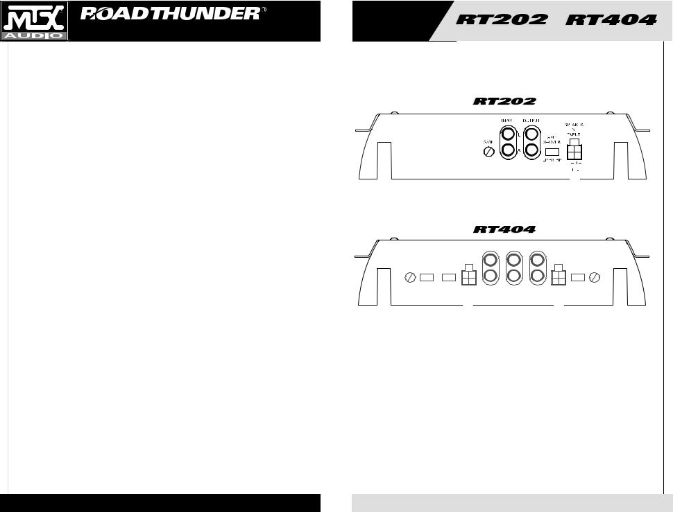
1.RCA Input Jacks – These RCA input jacks are for use with source units that have RCA or Line Level Outputs. An independent set of jacks are provided on the RT404 for front and rear stereo inputs. A source unit with a minimum level of 200mV is required for proper operation. The use of high quality twisted pair cables is recommended to decrease the possibility of radiated noise entering the system.
2.Input Select 2CH/4CH – This switch, found on the RT404, is used to match the amplifier’s input to the source unit’s output so all four channels of the amplifier are driven. If your source unit has 2 outputs (left and right) connect them to the amplifier’s front channel inputs, and place the input select switch in the 2CH position. If your source unit has 4 outputs, (left front, left rear, right front, right rear) connect them to the amplifier inputs and place the input select switch in the 4CH position. In the 4CH position, the fader on your source unit will operate.
3.Speaker Level Inputs – This input will allow the amplifier to operate from source units with speaker level outputs. Output speaker leads from the source unit should be tied directly to the wire harness provided with the amplifier.
Wire harness color codes: |
|
Grey/Black = Source unit right negative (-) |
White/Black = Source unit left negative (-) |
Solid Grey = Source unit right positive (+) |
Solid White = Source unit left positive (+) |
With the Smart-Engage™ auto-turn-on circuit, a remote turn-on wire is not necessary when connecting the speaker-level input wire harness to a high powered source unit. The amplifier will automatically turn on when music is received.
4.RCA Output – These RCA outputs allow for a signal to be sent to other amplifiers in a daisy-chain configuration. The RCA outputs on all Road Thunder series amplifiers will send a full-range signal to additional amplifiers.
5.Gain Controls – These controls are used to match the input sensitivity of the amplifier to the particular source unit that you are using. The controls are factory set to 1Vrms. Note that the RT404 has a separate gain control for front and rear channels.
6.Crossover Select – This switch controls the type of crossover configuration that you desire. Road Thunder series 2-channel amplifiers include a defeatable 18dB/octave, 85Hz crossover that is high pass/low pass or full range selectable. The RT404 four channel amplifier includes a defeatable 18dB/octave, 85Hz crossover that is high pass or full range for the front channels, and a high pass, low pass or full range for the rear channels.
Input Panel Layout

|
|
|
SPEAKER FRONT IN |
SUM OUT |
REAR IN SPEAKER |
|
|||
|
|
|
LEVEL |
|
|
|
LEVEL |
|
|
|
|
|
INPUT |
|
|
|
INPUT |
|
|
FRONT |
AMP |
RCA |
FRONT |
|
L |
L |
REAR |
AMP |
REAR |
|
|
|
|
|
|||||
GAIN |
X–OVER |
INPUT |
|
|
|
|
|
X–OVER |
GAIN |
|
|
|
|
|
R |
R |
|
|
|
|
FR HP |
2CH 4CH |
|
|
|
|
|
LP FR HP |
|
|
|
|
|||||||
|
|
R– L– |
|
|
|
R– L– |
|||
|
|
R+ L+ |
|
|
|
R+ L+ |
|||
4
5

AMPLIFIER OWNER’S MANUAL
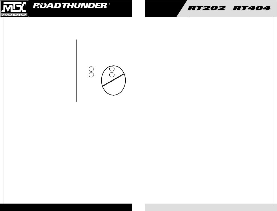
1. Fuses - For convenience, all amplifiers utilize ATC type fuses. For continued protection in the event that a fuse blows, replace the fuse only with the same value.
Caution: The power fuses on the amp are for protecting the amp against overdrive. To protect the vehicle’s electrical system, an additional fuse is required within 18" of the battery on the 12V+ cable.
RT202 – 20 Amp
RT404 – 25 Amp x 2
2. Power Terminal – This is the main power input for the amplifier and must be connected directly to the positive terminal of the car battery for the amplifier to operate properly. See the chart below for recommended cable sizes for each amplifier. Use caution when running this cable through the car. Try to avoid the input RCA cables, antenna cabling, or other sensitive equipment as the large amount of current flowing through this cable can induce noise into your system. It is also very important to have a tight connection to ensure maximum performance.
RT202 – 10 Gauge
RT404 – 8 Gauge
3.Ground Terminal – A good quality ground is required for your Road Thunder Amplifier to operate at peak performance. A short length of cable the same gauge as your power cable should be used to attach the ground terminal directly to the chassis of the car. Always scrape or sand any painted surfaces to expose bare metal where the ground wire will attach.
4.Remote Terminal – All Road Thunder Amplifiers can be turned on by applying 12 volts to this terminal. Typically this voltage is supplied by a wire from the source unit marked “remote” or “electric antenna”.
5.Speaker Terminals – As shown in the wiring diagrams, be sure to observe speaker polarity through the system. Failing to wire the speakers in proper phase could result in a loss of bass response and/or poor overall sound quality. Caution: Road Thunder amplifiers are not recommended for loads below 2 ohms stereo or 4 ohms bridged.
6.Power LED - A lighted LED indicates that power has been applied to the amplifier. +12V from the battery to the +BATT terminal and +12V from a switched ignition or remote lead from a head unit. An unlighted LED indicates power has been removed or the amplifier has overheated. In the case of the overheat condition, the amplifier will turn back on after it cools down.
Output Panel Layout
|
|
|
|
|
|
|
|
|
|
6
7
AMPLIFIER OWNER’S MANUAL
Adjusting the Gain
1.Turn the gain control on the amplifier all the way down.
2.Turn up the volume control on the source unit to approximately 3⁄4 of maximum.
3.Adjust the gain control on the amplifier until audible distortion occurs.
4.Adjust the gain control down until audible distortion disappears.
5.Follow steps 3-4 for other gain control settings. (RT404)
6.The amplifier is now calibrated to the output of the source unit.
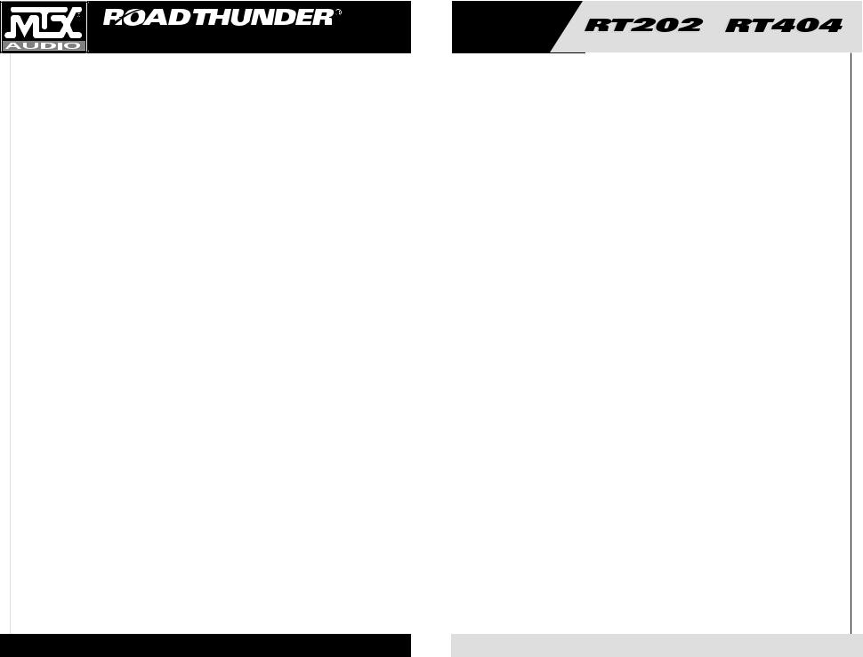
Typical Speaker
Wiring
Configurations
Stereo Amplifier
Bridge Mode Application
Impedance Requirement
4 ohm bridge minimum
2 ohm stereo minimum
|
|
8 ohm |
|
|
|
|
|
4 ohm |
|
|
|
||
|
|
8 ohm |
|
|
|
|
|
4 ohm |
|
|
|
||
|
|
|
|
|
|
|
|
|
|
|
|
|
|
|
+ |
- |
- |
+ |
|
|
+ |
- |
- |
+ |
|
||
|
L |
L |
R |
R |
|
|
L |
L |
R |
R |
|
||
|
|
AMP |
|
|
|
AMP |
|
||||||
Two 8 ohm Speakers |
Two 4 ohm Speakers |
||||||||||||
not
OK ok
Definitions of Common Terms
The following list of terms with their definitions is offered as help in understanding the set-up and operation of your amplifier.
1.Crossover (xover) - an electrical filter with high-pass or low-pass characteristics that divides the frequency range into playable bands for certain speakers. Subwoofers, midbass, midrange and tweeters are all designed to play different frequencies and should do so to avoid damage. The xover point is where the playable frequencies cross from one speaker to the next at -3dB below reference level.
2.Full-range - refers to signals which cover the entire audio frequency span from 20Hz to 20kHz.
3.High-pass - simply put, this blocks lower frequencies which damage smaller speakers, and passes the higher frequencies for smaller speakers like the midrange and tweeter.
4.Low-pass - you got it, this is the inverse of a high-pass. It blocks higher frequencies and passes the playable lower frequencies to the larger speakers, like subwoofers.
5.Impedance - the resistance to the flow of current in an alternating current circuit (such as with music). Line level circuits are typically a high impedance of several thousand ohms, while speaker level circuits are usually a low impedance of a few ohms.
6.Line level - the type of signal produced at the outputs of tape decks, CD tuners, preamplifiers, etc., with a typical value of a volt or less in a high impedance circuit.
7.Speaker level - the type of output that is meant to drive speakers. These signals are sometimes called high level and are usually connected by two conductor speaker wires.
8.Signal - the signal of an audio system is what is heard from the speakers. These signals may be high pass, low pass or full-range.
We don’t have enough space for Electronics 101, so if you have a good, bad or amusing question, please call us TOLL FREE at 800-CALL MTX! (800-225-5689)
Troubleshooting Guide
Read this if you wanna be a do-it-yourselfer or give us a call at 800-CALLMTX.
Problem |
Cause |
Solution |
No LED indication |
No +12V at remote connection |
Supply +12V to terminal |
|
No +12V at Power connection |
Supply +12V to terminal |
|
Insufficient ground connection |
Verify ground connection |
|
Blown power fuse |
Replace fuse |
LED on, no output |
Volume on head unit off |
Increase volume on head unit |
|
Speaker connections not made |
Make speaker connections |
|
Gain control on amplifier off |
Turn up gain |
|
Signal processing units off |
Apply power to signal processor |
|
All speakers blown |
Replace speakers |
Output distorted |
Head unit volume set too high |
Lower head unit volume |
|
Amplifier gain set too high |
Lower amplifier gain |
Balance reversed |
Speakers wired L + R reversed |
Wire speakers with correct orientation |
|
RCA inputs reversed |
Reverse RCA inputs |
Some balance reversed |
Some Speakers wired L + R |
Wire speakers with correct orientation |
|
reversed |
|
|
Some RCA inputs reversed |
Reverse appropriate RCA inputs |
Bass is weak |
Speakers wired out |
Wire with correct phase |
|
of phase |
|
|
Not using MTX woofers |
Buy MTX woofers |
Blowing fuses |
Excessive output levels |
Lower volume |
|
Amplifier defective |
Return for service |
8
9
AMPLIFIER OWNER’S MANUAL
Introduction
FELICITATIONS...
FRENCH |
vous félicitant de votre achat d’un nou- |
|
veau amplificateur MTX Audio Road |
||
|
||
|
Thunder! MTX a été depuis longtemps |
|
|
un leader dans l’industrie d’enclos |
|
|
mobiles et speakers, et nous sommes |
|
|
arrivés à un nouveau sommet avec le |
|
|
développement des nouveaux amplifi- |
|
|
cateurs MTX Road Thunder. Vous |
|
|
n’auriez pas pu choisir d’amplificateur |
|
|
plus fiable, plus puissant ou meilleur. |
Nous fabriquons chaque amplificateur en employant la Technologie Surface Mount le plus récent et intelligent . Quelques advantages du nouveau dessin sont les perfectionnements aux propriétés mécaniques et électriques de l’amplificateur. Les mécanismes SMT ont de substantiellement plus courtes longueurs internes et externes. Cela réduit l’inductance et la capacitance égarées, qui résulte en une reproduction musicale plus pure et plus exacte avec considérablement moins d’intervention du bruit. Le SMT mounter produit des cartes d’amplificateur avec plus petits et plus légèrs composants qui sont plus résistants aux vibrations inhérentes dans l’environnement auto-
mobile.
Nous voulons tout faire pour assurer que vous obtenez la haute performance continue de votre amplificateur MTX Road Thunder, donc nous vous recommandons de l’avoir installé professionellement par votre vendeur agréé.
COMMENT UTILISER CE MANUEL
Si vous installez cet amplificateur vousmême, nous vous recommandons de lire ce manuel de la première à la dernière page avant de l’installer. Familiarisez-vous avec les caractéristiques et les détails des panneaux entrée-sortie. Vérifiez que vous avez tout l’équipement dont vous avez besoin. Puis suivez les instructions d’installation point par point qui se trouvent. Vous pouvez trouver des échantillons des diagrammes d’installation sur le Web à notre site :
mtx.com
Si vous avez des questions, écrivez ou téléphonez-nous à :
MTX Audio
4545 E. Baseline Rd. Phoenix, AZ 85042 602-438-4545 800-CALL MTX technical@mtx.com mtx.com
Caractéristiques
•Iso-Feet™ uniques, isolants en caoutchouc
•Connecteurs nickelés, d’un type bloc terminal à usage industriel
•Speaker et les entrées de niveau bas
•Le contrôle Input Select 2CH/4CH sur RT404 fonctionne comme un connecteur Y encastré
•Harnais métallique codifié par couleurs
•Auto-allumage Smart-Engage ™ pour intégration facile avec les unités de tête d’usine
•Filtre passe-haut/passe-bas 18dB/octave contournable intégré à 85 Hz
•Le croisement du canal avant RT404 est un 18dB/octave défait (defeatable), haut laissez-passer, à 85Hz
•Sensibilité d’entrée réglable
•Possibilité de ponter l’ampli et trimode possible
•Source d’alimentation régulée à transistor Mosfet PWM régulé
•Nouveaux transformateurs haute puissance plus fiables
•Sortie isolée tamponnée pour la connexion en guirlande de plusieurs amplis
•Dessin N-Canal pur
•Technologie Intelligente Surface Mount
•Topologie de circuit moteur 100 % discret de classe A
•Circuit de protection informatisé temps réel
•Montage carte-mère antichoc
•Marche/arrêt transparent au plan acoustique
Specifications
RT202
RMS Power measured at 14.4 Volts DC:
37.5 Watts x 2 into a 4 Ohm load with < 1% THD 75 Watts x 2 into a 2 Ohm load with < 1% THD
150 Watts bridged into a 4 Ohm load with < 1% THD
Dynamic Power measured at 14.4 Volts DC:
50 Watts x 2 into a 4 Ohm load
100 Watts x 2 into a 2 Ohm load
200 Watts bridged into a 4 Ohm load
Signal to Noise Ratio: 100dB A-Weighted
(Referenced to Rated PWR at 1VRMS Input Sensitivity)
Frequency Response: 20-20,000 Hz ±.25dB
Crossover: Defeatable, 18dB/octave at 85 Hz, selectable for high pass, low pass
Dimensions: Including Iso-Feet™
7.98" x 9.75" x 2.1" (20.3cm x 24.8cm x 5.3cm)
RT404
RMS Power measured at 14.4 Volts DC:
37.5 Watts x 4 into a 4 Ohm load with < 1% THD 75 Watts x 4 into a 2 Ohm load with < 1% THD
150 Watts x 2 bridged into a 4 Ohm load with < 1% THD
Dynamic Power measured at 14.4 Volts DC:
50 Watts x 4 into a 4 Ohm load
100 Watts x 4 into a 2 Ohm load
200 Watts x 2 bridged into a 4 Ohm load
Signal to Noise Ratio: 100dB A-Weighted
(Referenced to Rated PWR at 1VRMS Input Sensitivity)
Frequency Response: 20-20,000 Hz ±.25dB
Crossover: Defeatable, 18dB/octave at 85 Hz, selectable for high pass, low pass, or full range on rear channels and high pass or full range for front channels
Dimensions: Including Iso-Feet™
11.5" x 9.75" x 2.1" (29.2cm x 24.8cm x 5.3cm)
10
11
 Loading...