


MTD S230, 250, 260, 230, 240 User Manual
...Safety • Set-Up • Operation • Adjustments • Maintenance •Troubleshooting • Parts Lists • Warranty
OPERATOR’S MANUAL
Model 230, S230
Model 240, S240
Model 250, S250
Model 260, S260
Single-Stage Snow Thrower Model 261, S261
IMPORTANT
READ SAFETY RULES AND INSTRUCTIONS CAREFULLY BEFORE OPERATION
Warning: This unit is equipped with an internal combustion engine and should not be used on or near any unimproved forest-covered, brushcovered or grass-covered land unless the engine’s exhaust system is equipped with a spark arrester meeting applicable local or state laws (if any). If a spark arrester is used, it should be maintained in effective working order by the operator. In the State of California the above is required by law (Section 4442 of the California Public Resources Code). Other states may have similar laws. Federal laws apply on federal lands. A spark arrester for the muffler is available through your nearest engine authorized service dealer or contact the service department, P.O. Box 361131 Cleveland, Ohio 44136-0019.
For US Customers: MTD LLC, P.O. BOX 361131 CLEVELAND, OHIO 44136-0019 |
FORM NO. 769-00805C |
|
PRINTED IN U.S.A. For Canadian Customers: MTD Products Ltd., P.O. BOX 1386, KITCHENER, ONTARIO N2G 4J1 |
05/17/06 |
|
This Operator’s Manual is an important part of your new snow thrower. It will help you assemble, prepare and maintain the unit for best performance. Please read and understand what it says.
Table of Contents
Safety Labels ...................................................... |
3 |
Adjustments & Maintenance ........................... |
10 |
Safe Operation Practices................................... |
4 |
Off-Season Storage.......................................... |
12 |
Set Up & Adjustment.......................................... |
6 |
Trouble Shooting.............................................. |
13 |
KnowYour SnowThrower.................................. |
7 |
Illustrated Parts Lists....................................... |
14 |
Operation............................................................. |
8 |
Warranty............................................................ |
18 |
Finding and Recording Model Number
BEFORE YOU START ASSEMBLING
YOUR NEW EQUIPMENT,
please locate the model plate on the equipment and copy the the model number and the serial number to the sample model plate provided to the right. You can locate the model plate by standing at the operating position and looking down at the frame.
Customer Support
Please do NOT return the unit to the retailer from which it was purchased, without first contacting Customer Support.
If you have difficulty assembling this product or have any questions regarding the controls, operation or maintenance of this unit, you can seek help from the experts. Choose from the options below:
1.Visit www.mtdcanada.ca for many useful suggestions, click on Customer Support button.
2.Call a Customer Support Representative: For US Customers: 1-330-220-4MTD (4683)or 1-800-800-7310
For Canadian Customers: 1-800-668-1238
3.The engine manufacturer is responsible for all enigne-related issues with regards to performance, power-rating, specifications, warranty and service. Please refer to the engine manufacturer’s Owner’s/Operator’s Manual, packed separately with your unit, for more information.
Please have your unit’s model number and serial number ready when you call. See previous section to locate this information. You will be asked to enter the serial number in order to process your call.
2
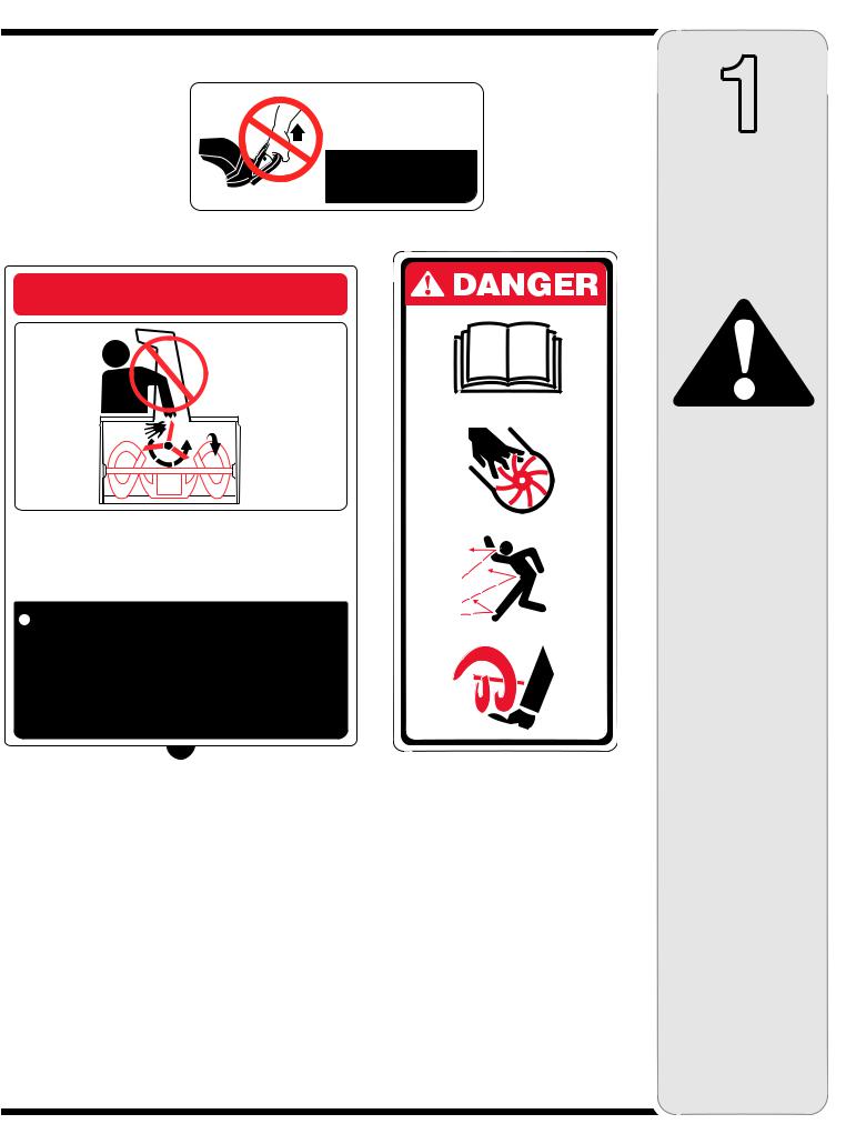
FOR TURNING,
NOT LIFTING
POUR TOURNER,
PAS POUR LE LEVAGE
 DANGER
 NEVER PUT HAND IN CHUTE. CAN
AMPUTATE HANDS AND FINGERS.
 STOP ENGINE AND AUGER BEFORE USING
CLEAN-OUT TOOL OR STICK.
NE PLACEZ JAMAIS VOS MAINS DANS LA
GOULOTTE. LES PIÈCES EN MOUVEMENT
PEUVENT AMPUTER MAINS ET DOIGTS.
 ARRÊTEZ LE MOTEUR ET LA TARIÈRE AVANT
D'UTILISER L'OUTIL DE DÉGAGEMENT
DE LA GOULOTTE OU UN BÂTON.
1
Safety Labels
WARNING
This symbol points out important safety instructions which, if not followed, could endanger the personal safety and/or property of yourself and others.
Read and follow all instructions in this manual before attempting to operate this machine. Failure to comply with these instructions may result in personal injury. When you see this symbol.
HEED ITS WARNING!
Your Responsibility
Restrict the use
of this power machine to persons who read, understand
and follow the warnings and instructions
in this manual
and on the machine.
3
2
Safe
Operation Practices
WARNING
This symbol points out important safety instructions which, if not followed, could endanger the personal safety and/ or property of yourself and others. Read and
follow all instructions in this manual before attempting to operate this machine. Failure to comply with these instructions may result in personal injury. When you see this symbol.
HEED ITS WARNING!
Your Responsibility
Restrict the use of this power machine to persons who read, understand and follow the warnings and instructions in this manual and on the machine.
WARNING: Engine Exhaust, some of its constituents, and certain vehicle components contain or emit chemicals known to State of California to cause cancer and birth defects or other reproductive harm.
DANGER: This machine was built to be operated according to the rules for safe operation in this manual. As with any type of power equipment, carelessness or error on the part of the operator can result in serious injury. This machine is capable of amputating hands and feet and throwing objects. Failure to observe the following safety instructions could result in serious injury or death.
Training
1.Read, understand, and follow all instructions on the machine and in the manual(s) before attempting to assemble and operate.Keep this manual in a safe place for future and regular reference and for ordering replacement parts.
2.Be familiar with all controls and their proper operation. Know how to stop the machine and disengage them quickly.
3.Never allow children under 14 years old to operate this machine.Children 14 years old and over should read and understand the operation instructions and safety rules in this manual and should be trained and supervised by a parent.
4.Never allow adults to operate this machine without proper instruction.
5.Thrown objects can cause serious personal injury.Plan your snow-throwing pattern to avoid discharge of material toward roads, bystanders and the like.
6.Keep bystanders, helpers, pets and children at least 75 feet from the machine while it is in operation.Stop machine if anyone enters the area.
7.Exercise caution to avoid slipping or falling, especially when operating in reverse.
Preparation
1.Thoroughly inspect the area where the equipment is to be used. Remove all doormats, newspapers, sleds, boards, wires and other foreign objects, which could be tripped over or thrown by the auger/impeller.
2.Always wear safety glasses or eye shields during operation and while performing an adjustment or repair to protect your eyes. Thrown objects which ricochet can cause serious injury to the eyes.
3.Do not operate without wearing adequate winter outer garments. Do not wear jewelry, long scarves or other loose clothing, which could become entangled in moving parts. Wear footwear which will improve footing on slippery surfaces.
4.Use a grounded three-wire extension cord and receptacle for all units with electric start engines.
5.Adjust collector housing height to clear gravel or crushed rock surfaces.
6.Disengage all control levers before starting the engine.
7.Never attempt to make any adjustments while engine is running, except where specifically recommended in the operator’s manual.
8.Let engine and machine adjust to outdoor temperature before starting to clear snow.
9.To avoid personal injury or property damage use extreme care in handling gasoline. Gasoline is extremely flammable and the vapors are explosive. Serious personal injury can occur when gasoline is spilled on yourself or your clothes, which can ignite. Wash your skin and change clothes immediately.
a.Use only an approved gasoline container.
b.Extinguish all cigarettes, cigars, pipes and other sources of ignition.
c.Never fuel machine indoors.
d.Never remove gas cap or add fuel while the engine is hot or running.
e.Allow engine to cool at least two minutes before refueling.
f.Never over fill fuel tank. Fill tank to no more than ½ inch below bottom of filler neck to provide space
for fuel expansion.
g.Replace gasoline cap and tighten securely.
h.If gasoline is spilled, wipe it off the engine and equipment. Move machine to another area. Wait 5 minutes before starting the engine.
i.Never store the machine or fuel container inside where there is an open flame, spark or pilot light (e.g. furnace, water heater, space heater, clothes dryer etc.).
j.Allow machine to cool at least 5 minutes before storing.
4
Operation
1.Do not put hands or feet near rotating parts, in the auger/impeller housing or chute assembly. Contact with the rotating parts can amputate hands and feet.
2.The auger/impeller control lever is a safety device. Never bypass its operation. Doing so makes the machine unsafe and may cause personal injury.
3.The control levers must operate easily in both directions and automatically return to the disengaged position when released.
4.Never operate with a missing or damaged chute assembly. Keep all safety devices in place and working.
5.Never run an engine indoors or in a poorly ventilated area. Engine exhaust contains carbon monoxide, an odorless and deadly gas.
6.Do not operate machine while under the influence of alcohol or drugs.
7.Muffler and engine become hot and can cause a burn. Do not touch.
8.Exercise extreme caution when operating on or crossing gravel surfaces. Stay alert for hidden hazards or traffic.
9.Exercise caution when changing direction and while operating on slopes.
10.Plan your snow-throwing pattern to avoid discharge towards windows, walls, cars etc. Thus, avoiding possible property damage or personal injury caused by a ricochet.
11.Never direct discharge at children, bystanders and pets or allow anyone in front of the machine.
12.Do not overload machine capacity by attempting to clear snow at too fast of a rate.
13.Never operate this machine without good visibility or light. Always be sure of your footing and keep a firm hold on the handles. Walk, never run.
14.Disengage power to the auger/impeller when transporting or not in use.
15.Never operate machine at high transport speeds on slippery surfaces. Look down and behind and use care when backing up.
16.If the machine should start to vibrate abnormally, stop the engine, disconnect the spark plug wire and ground it against the engine. Inspect thoroughly for damage. Repair any damage before starting and operating.
17.Disengage all control levers and stop engine before you leave the operating position (behind the handles). Wait until the auger/impeller comes to a complete stop before unclogging the chute assembly, making any adjustments, or inspections.
18.Never put your hand in the discharge or collector openings. Always use the clean-out tool provided to unclog the discharge opening. Do not unclog chute assembly while engine is running. Shut off engine and remain behind handles until all moving parts have stopped before unclogging.
19.Use only attachments and accessories approved by the manufacturer (e.g. wheel weights, tire chains, cabs etc.).
20.If situations occur which are not covered in this manual, use care and good judgment. Contact your dealer or call (800) 800-7310 for assistance and the name of your nearest servicing dealer..
Maintenance & Storage
1.Never tamper with safety devices. Check their proper operation regularly. Refer to the maintenance and adjustment sections of this manual.
2.Before cleaning, repairing, or inspecting machine disengage all control levers and stop the engine. Wait until the auger/impeller come to a complete stop. Disconnect the spark plug wire and ground against the engine to prevent unintended starting.
3.Check bolts and screws for proper tightness at frequent intervals to keep the machine in safe working condition. Also, visually inspect machine for any damage.
4.Do not change the engine governor setting or over-speed the engine. The governor controls the maximum safe operating speed of the engine.
5.Snow thrower shave plates and skid shoes are subject to wear and damage. For your safety protection, frequently check all components and replace with original equipment manufacturer’s (OEM) parts only. “Use of parts which do not meet the original equipment specifications may lead to improper performance and compromise safety!”
6.Check controls periodically to verify they engage and disengage properly and adjust, if necessary. Refer to the adjustment section in this operator’s manual for instructions.
7.Maintain or replace safety and instruction labels, as necessary.
8.Observe proper disposal laws and regulations for gas, oil, etc. to protect the environment.
9.Prior to storing, run machine a few minutes to clear snow from machine and prevent freeze up of auger/impeller.
10.Never store the machine or fuel container inside where there is an open flame, spark or pilot light such as a water heater, furnace, clothes dryer etc.
11.Always refer to the operator’s manual for proper instructions on off-season storage.
Do not modify engine
To avoid serious injury or death, do not modify engine in any way.Tampering with the governor setting can lead to a runaway engine and cause it to operate at unsafe speeds.Never tamper with factory setting of engine governor.
Notice regarding Emissions
Engines which are certified to comply with California and federal EPA emission regulations for SORE (Small Off Road Equipment) are certified to operate on regular unleaded gasoline, and
may include the following emission control systems: Engine Modification (EM) and Three Way Catalyst (TWC) if so equipped.
Your Responsibility
Restrict the use of this power machine to persons who read, understand and follow the warnings and instructions in this manual and on the machine.
2
Safe
Operation Practices
WARNING
This symbol points out important safety instructions which, if not followed, could endanger the personal safety and/ or property of yourself and others. Read and
follow all instructions in this manual before attempting to operate this machine. Failure to comply with these instructions may result in personal injury. When you see this symbol.
HEED ITS WARNING!
Your Responsibility
Restrict the use of this power machine to persons who read, understand and follow the warnings and instructions in this manual and on the machine.
5

3
Setup And Adjustment
NOTE: This Operator’s Manual covers several models. Snow thrower features vary by model. Not all features discussed in this manual are applicable to all snow thrower models.
NOTE: All references to left or right side of the snow thrower is from the operating position only.
IMPORTANT:
Do not use the chute handle to lift the snow thrower.
1
2
Figure 1
2
3

 1
1
Figure 2
Chute Handle
Contents of Carton
Carton contents are listed below with part numbers in parentheses.
1. Two Ignition Keys (725-0201)
2.2.6 oz Bottle of 2 Cycle Oil (737-04037)
3.Extension Cord (if so equipped) (629-0236)
WARNING: Disconnect the spark plug wire and ground it against the engine to prevent unintended starting.
Positioning the Upper Handle
1.Remove packing material, if present.
2.Making sure not to pinch the cable in the process, pivot the upper handle into the operating position as illustrated in Figure 1 until it clicks into place.
3.Tighten the star knobs to secure the handle in place as in Figure 1.
Assembling the Discharge Chute
For shipping reasons, the snow thrower has been packaged with the upper chute pivoted all the way down. To pivot it upward, proceed as follows:
1.Turn the chute until the chute opening is facing straight ahead. Remove the wing knob, flat washer and carriage bolt from the lower chute. See Figure 2.
2.Pivot the upper chute upward over the lip on the lower chute so that there is NO gap between the upper chute and the lower chute.
3.Resecure with the hardware just removed. If installed correctly, your snow thrower should look like Figure 3.
IMPORTANT: Do not use the chute handle to lift the snow thrower.
Figure 3
6
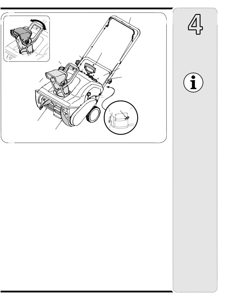
Auger Control Handle
Electric Starter Button
(if equipped)
Starter Handle
Figure 4A |
Fuel Cap |
|
Primer
Spark Plug Access
Chute Assembly
Choke Lever
Shave Plate
Auger
Figure 4
IMPORTANT: This unit runs on a mixture of gasoline and oil. Do NOT operate the snow thrower without first reading the engines operator’s manual for instructions regarding proper fuel and engine oil.
Choke Lever
Activating choke control closes the choke plate on carburetor and aids in starting engine. Refer to the engine manual packed with unit for more detailed instructions.
Primer
Depressing primer forces fuel directly into engine’s carburetor to aid in cold-weather starting. Refer to engine manual packed with unit for more detailed instructions.
Spark Plug Cover
Remove spark plug cover to access spark plug.
Auger
When engaged, the augers rotation draws snow into the auger housing and throws it out the discharge chute. Rubber paddles on the augers also aid in propelling the unit as they come in contact with the pavement.
Auger Control Handle
Located on the upper handle, the auger control handle is used to engage and disengage drive to the auger. Squeeze the control handle against the upper handle to engage auger; release it to disengage.
Ignition Key
Ignition key must be present, inserted in key switch, and in the “ON” position for engine to start.
Recoil Starter
The starter handle is used to manually start the engine.
Electric Starter Button (If so equipped)
Pressing the electric starter button engages the engine’s electric starter when plugged into a 120V power source
Electric Starter Plug (If so equipped)
Requires use of a two-prong outdoor extension cord (packed with the snow thrower) and a 120V power source/wall outlet.
Discharge Chute / Chute Handle
Rotate the discharge chute to the left or right using chute handle. Pitch of the discharge chute controls angle at which the snow is thrown. Loosen wing knob on side
of the discharge chute before pivoting discharge chute upward or downward. Retighten the knob once desired position has been achieved.
Shave Plate
The shave plate maintains contact with pavement as the snow thrower is propelled, allowing snow close to pavement’s surface to be discharged.
4
Know
Your Snow Thrower
IMPORTANT:
This unit runs on a mixture of gasoline and oil. Do NOT operate the snow thrower without first reading the engines operator’s manual for instructions regarding proper fuel and engine oil.
7

5
Operation
WARNING
Read, understand, and follow all instructions and warnings on the machine and in this manual before operating.
Use extreme care when handling gasoline. Gasoline is extremely flammable and the vapors are explosive. Never fuel the machine indoors or while the engine is hot or running. Extinguish cigarettes, cigars, pipes and other sources of ignition.
The electric starter must be used with a properly grounded three-prong receptacle at all times to avoid the possibility of electric shock. Follow all instructions carefully prior to operating the electric starter.
Before Starting
WARNING: Before starting the engine, read, understand, and follow all instructions and warnings on the machine and in this manual.
1.The spark plug wire was disconnected for safety. Attach spark plug wire to spark plug before starting.
IMPORTANT: For complete and detailed engine starting, stopping and storing instructions, it is recommended that you read the engine manual also included with this unit.
Fuel And Oil Mixture
WARNING: Use extreme care when handling gasoline. Gasoline is extremely flammable and the vapors are explosive. Never fuel machine indoors or while the engine is hot or running. Extinguish cigarettes, cigars, pipes and other sources of ignition.
IMPORTANT: This unit runs on a mixture of gasoline and oil. Do NOT operate the snow thrower without first reading the engines operator’s manual for detailed instructions regarding proper fuel and engine oil.
Do NOT operate the snow thrower without the fuel cap securely in place on the fuel tank.
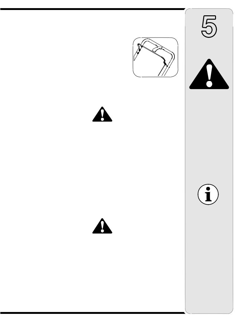
Positioning the Discharge Chute
1.Loosen the star knob found on the left side of the discharge chute and pivot the upper chute upward
or downward to the desired pitch. Retighten the star knob before
operating the snow Figure 5 thrower.
2.Rotate the discharge chute to the left or right using the chute handle. See Figure 5.
To Start Engine
1.Insert ignition key into slot.
2.Now follow the instructions below as it pertains to your unit. See Figure 5 for location of controls.
Electric Starter(if equipped)
WARNING: The electric starter must be used with a properly grounded three-prong receptacle at all times to avoid the possibility of electric shock. Follow all instructions carefully prior to operating the electric starter.
1.The electric starter is equipped with a grounded threewire power cord and plug, and is designed to operate on 120 volt AC household current.
2.Determine that your house wiring is a three-wire grounded system. Ask a licensed electrician if you are not certain.
3.If your home wiring system is not a three-wire grounded system, do not use this electric starter under any conditions.
4.If your home electrical system is grounded, but a three-hole receptacle is not available, one should be installed by a licensed electrician before using the electric starter.
5.If you have a grounded three-prong receptacle, proceed as follows.
6.Move Choke Control to the “Full” position.
7.Push Primer three (3) times, making sure to cover vent hole when pushing.
8.Connect power cord to switch box on dash panel. Plug the other end of power cord into a three-prong 120-volt, grounded, AC receptacle.
9.Push starter button to crank engine.
10.When engine starts, release starter button, and move choke gradually to 1/2 Choke until the engine runs smoothly. Next move Choke to OFF. If engine falters, move choke immediately to FULL and then gradually to 1/2 then to OFF.
11.Disconnect the power cord. Always unplug from the outlet first, and then from the snow thrower.
Recoil Starter
1.Move choke lever to FULL choke position (cold engine start).
2.If engine is warm, place choke in OFF position instead of FULL.
3.Push Primer three (3) times, making sure to cover vent hole when pushing.
4.If engine is warm, push primer button only once.
NOTE: Always cover vent hole in primer button when pushing. Additional priming may be necessary for first start if temperature is below 15 degrees Fahrenheit.
5.Grasp starter handle and pull rope out slowly, until it pulls slightly harder. Let rope rewind slowly.
6.Pull starter handle rapidly. Do not allow handle to snap back. Allow it to rewind slowly while keeping a firm hold on the starter handle.
8
7.As engine warms up and begins to operate evenly, rotate choke lever slowly to the 1/2 Choke position. When the engine begins to run smoothly, move the choke to the OFF position. If engine falters, return to FULL choke, then slowly move to 1/2 then OFF position.
To Stop Engine
1.To stop engine, turn ignition key counter-clockwise. Disconnect the spark plug wire from the spark plug to prevent accidental starting while equipment is unattended.
To help prevent possible freeze-up of starter, proceed as follows:
1.Run engine for a few minutes before stopping to help dry off any moisture on the engine.
2.Electric Starter: Connect power cord to switch box on engine, then to 120 volt AC receptacle. With the engine running, push starter button and spin the starter for several seconds. The unusual sound made by spinning the starter will not harm engine or starter. Disconnect the power cord from receptacle first, and then from switch box.
3.Recoil Starter: With engine running, pull starter rope with a rapid, continuous full arm stroke three or four times. Pulling the starter rope will produce a loud clattering sound, which is not harmful to the engine or starter.
4.Wipe all snow and moisture from the carburetor cover in the area of the control levers. Also, move control levers back and forth several times. Leave choke control in the FULL choke position.
5.Remove ignition key and disconnect spark plug wire to prevent accidental starting.
Operating the SnowThrower
The pitch of the chute assembly controls the angle at which the snow is thrown.
1.Loosen the star knob found on the left side of the chute assembly and
pivot the upper chute upward or downward to the desired pitch. Retighten the star knob before operating the snow thrower.
2.Position the chute
assembly opening by using the Chute
Handle to throw the snow in the desired direction. See inset Figure 6.
Clearing Snow
WARNING: Never operate the snow thrower with bystanders in front of or near the discharge chute opening.
1.Engage the auger by squeezing the auger control handle against the upper handle. See Figure 5.
2.Lift up slightly on the handle to allow the rubber paddles on the auger to contact the pavement and propel the snow thrower forward. Pushing downward on the handle will raise the augers off the ground and stop forward motion.
3.Discharge snow downwind whenever possible. Slightly overlap each previously cleared path.
NOTE: Excessive upward pressure on the handle will result in premature wear on the rubber auger blades which would not be covered by warranty.
OperatingTips
1.Run the engine for a few minutes before stopping to help dry any moisture on the engine.
2.Clean the snow thrower thoroughly after each use.
WARNING: Muffler, engine and surrounding areas become hot and can cause a burn. Be careful and do not touch when hot.
5
Operation
WARNING
Muffler, engine and surrounding areas become hot and can cause a burn. Do not touch.
Never operate the snow thrower with bystanders in front of or near the discharge chuteopening.
NOTE: Excessive upward pressure on the handle will result in premature wear on the rubber auger blades which would not be covered by warranty.
9
6
Adjustments
&
Maintenance
WARNING
Disconnect the spark plug wire
and ground it against the engine to prevent unintended starting.
NEVER attempt to make any adjustments while
the engine is running, except where specified in
the operator’s manual.
Before servicing, repairing, or inspecting, disengage the control bail and stop engine. Wait until all moving parts have come to a complete stop.
Side View
Figure 7
Figure 8
WARNING: Disconnect the spark plug wire and ground it against the engine to prevent unintended starting.
WARNING: NEVER attempt to make any adjustments while the engine is running, except where specified in the operator’s manual.
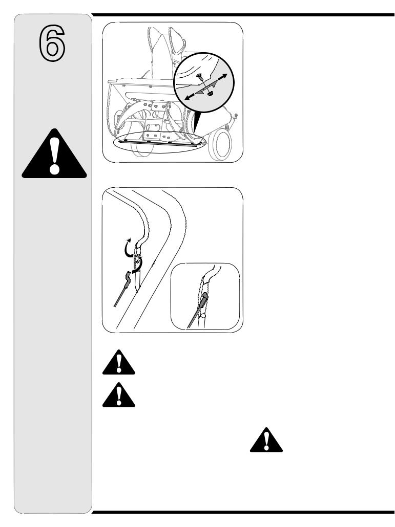
Shave Plate
1.To check the adjustment of the shave plate, place the unit on a level surface. The wheels, shave plate and augers should all contact level surface. Note that if the shave plate is adjusted too high, snow may blow under the housing. If the shave plate wears out excessively, or the unit does not self-propel, the shave plate may be too low and needs to be adjusted.
NOTE: On new units or units with a new shave plate installed, the augers may be slightly off the ground.
2.To adjust, tip the snow thrower back so that it rests on the handle. Loosen the lock nuts and bolts which secure the shave plate to the housing. See Figure 7.
Move the shave plate to desired position and retighten the nuts and bolts securely.
Replacing Shave Plate
The shave plate is attached to the bottom of the auger housing and is subject to wear. It should be checked periodically. There are two wearing edges and the shave plate can be reversed. Refer to Figure 7.
1.Remove the carriage bolts and hex lock nuts which attach it to the snow thrower housing.
2.Install new shave plate, making sure the heads of the carriage bolts are on the inside of the housing.
3.Adjust the shave plate according to instructions above. Tighten the nuts securely before operating the snow thrower.
NOTE: For information regarding the price and availability of Shave Plate Kit refer to customer support on page 2.
Control Cable
As a result of both the control cable and the drive belt stretching due to wear, periodic adjustments may be necessary.
If the auger seems to hesitate when rotating while the engine maintains a constant speed, an adjustment is necessary. Proceed as follows:
The upper hole in the control handle provides for an adjustment in cable tension. To adjust, disconnect the end of control cable from the bottom hole in the control handle and reinsert it in the upper hole. Insert the cable from the outside as shown in Figure 8. Test the snow thrower to see if there is a noticeable difference.
Carburetor
WARNING: If any adjustments need to be made to the engine while the engine is running (e.g. carburetor), keep clear of all moving parts. Be careful of muffler, engine and other surrounding heated surfaces.
1.Refer to the separate engine manual, packed with your unit, for carburetor adjustment information.
10
 Loading...