


700 / 710
MTD Products Aktiengesellschaft • Saarbrücken • Germany |
A |
Part No: 769-01319 12/04 |
English
Français
Deutsch
Italiano
Português
Español
 11
11
 21
21
 31
31
 41
41
 51
51
 61
61
2
KNOW YOUR UNIT |
|
FAMILIARISEZ-VOUS AVEC L’APPAREIL |
|
LERNEN SIE IHR GERÄT |
2 |
PANORAMICA SULL’UNITÀ |
|
FAMILIARIZE-SE COM A SUA MÁQUINA |
|
CONOZCA SU UNIDAD |
3 |
 4
4
9
8
5
10
12
11
13
14
6
16
7
15
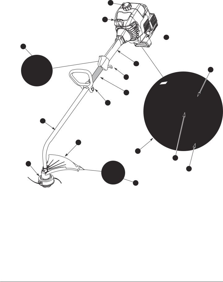
Description |
Parts |
|
|
|
1. |
Power |
|
9. |
Ignition Switch |
2. |
Fuel Cap |
|
10. |
Throttle Trigger |
3. |
Starter |
Grip |
11. |
D-Handle |
4. |
Spark Plug |
|
12. |
Limiter Sleeve |
5. |
Choke |
|
13. |
Shaft Tube |
6. |
Primer |
|
14. |
Cutting Attachment Guard |
7. |
Air Filter/Muffler Cover |
15. |
Line Cutting Blade |
|
8. |
Shaft Tube Grip |
16. |
Cutting Attachment |
|
Description des pièces
1.Tête d'entraînement
2.Bouchon du carburant
3.Poignée de la corde de démarrage
4.Bougie
5.Levier d'étrangleur
6.Amorceur
7.Couvercle du filtre à air/silencieux
8.Poignée
9.Interrupteur
10.Gâchette d’accélération
11.Poignée en D
12.Manchon du limiteur
13.Tube
14.Carter de protection de coupe
15.Coupe-fil
16.Bobine de fil
3

Beschreibung der Teile |
Descrição das peças |
||
1. |
Motor |
1. |
Motore |
2. |
Tankdeckel |
2. |
Tappo del serbatoio |
3. |
Griff des Anlassers |
3. |
Impugnatura del cavo per l'avvio |
4. |
Zündkerze |
4. |
Candela |
5. |
Starterhebel |
5. |
Leva dello starter |
6. |
Ansaugpumpe |
6. |
Cicchetto |
7. |
Gehäuse des Luftfilters/Abgasrohrs |
7. |
Carter del filtro dell'aria /tubo di scappamento |
8. |
Griff |
8. |
Impugnatura |
9. |
Schalter |
9. |
Interruttore |
10. |
Beschleunigungsdrücker |
10. |
Acceleratore |
11. |
D-förmiger Griff |
11. |
Impugnatura a D |
12. |
Begrenzermanschette |
12. |
Manicotto di limitazione |
13. |
Rohr |
13. |
Tubo |
14. |
Schutzgehäuse für den Schnitt |
14. |
Carter di protezione del taglio |
15. |
Fadenabschneider |
15. |
Filo di taglio |
16. |
Fadenspule |
16. |
Bobina del filo |
Descrizione dei componenti
1.Motor
2.Tampa do depósito
3.Pega do lançador
4.Vela
5.Alavanca do starter
6.Bomba de escorvamento
7.Cárter do filtro de ar/escape
8.Punho
9.Interruptor
10.Gatilho de aceleração
11.Pega em D
12.Saia limitadora
13.Tubo
14.Resguardo de protecção de corte
15.Corta-fio
16.Bobina de fio
Componentes
1.Motor
2.Tapón del depósito de combustible
3.Asa del arrancador de cuerda
4.Bujía
5.Palanca del starter
6.Bomba de cebado
7.Cárter del filtro de aire/tubo de escape
8.Asa
9.Interruptor
10.Gatillo de aceleración
11.Asa en forma de D
12.Manguito limitador
13.Tubo
14.Cárter de protección de corte
15.Cortahilo
16.Bobina de hilo
4
1 |
2 |
3 |
6 |
4 |
5 |
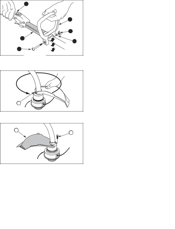
Fig. 1
Description of Parts – Figs. 1–3 |
|
|
|
1. |
Shaft Tube Grip |
6. |
Limiter Sleeve |
2. |
Handle |
7. |
Clamp Assembly |
3. |
Wing Nut |
8. |
Cutting Attachment |
4. |
Washer |
|
Guard |
5. |
Bolt |
9. |
Screws (4) |
Description des pièces – Figs. 1–3 |
|
||
1. |
Poignée |
6. |
Manchon du limiteur |
2. |
Poignée en D |
7. |
Dispositif de fixation |
3. |
Vis papillon |
8. |
Carter de protection |
4. |
Rondelle |
|
de coupe |
5. |
Boulon |
9. |
4 vis |
Beschreibung der Teile – Abb. 1–3 |
|
|||
1. |
Griff |
6. |
Begrenzer- |
|
2. |
D-förmiger Griff |
|
manschette |
|
3. |
Flügelschraube |
7. |
Befestigungs- |
|
4. |
Unterlegscheibe |
|
vorrichtung |
|
8. |
Schutzgehäuse für |
|||
5. |
Bolzen |
|||
|
den Schnitt |
|||
7 |
|
|
||
|
|
|
||
|
|
9. |
4 Schrauben |
|
|
|
Descrizione dei componenti – figg. 1–3 |
|||
|
|
1. |
Impugnatura |
6. |
Manicotto di |
8 |
9 |
2. |
Impugnatura a D |
|
limitazione |
|
3. |
Vite a farfalla |
7. |
Dispositivo di |
|
|
|
||||
|
|
4. |
Rondella |
|
fissaggio |
|
|
8. |
Carter di protezione |
||
|
|
5. |
Bullone |
||
|
|
9. |
4 viti |
||
|
|
|
|
||
|
Descrição das peças – Figuras 1–3 |
||||
Fig. 3 |
1. |
Punho |
6. |
Saia limitadora |
|
2. |
Pega em D |
7. |
Dispositivo de |
||
|
|||||
|
3. |
Porca borboleta |
|
fixação |
|
|
8. |
Resguardo de |
|||
|
4. |
Anilha |
|||
|
|
protecção de corte |
|||
|
5. |
Parafuso |
|
||
|
9. |
4 parafusos |
|||
|
|
|
|||
|
Descripción de las piezas – Fig. 1–3 |
||||
|
1. |
Asa |
6. |
Manguito limitador |
|
|
2. |
Asa en forma de D |
7. |
Dispositivo de |
|
|
3. |
Tornillo de mariposa |
|
fijación |
|
|
4. |
Arandela |
8. |
Cárter de |
|
|
5. |
Perno |
|
protección de corte |
|
|
9. |
4 tornillos |
|||
|
|
|
|||
5
2 |
1 |
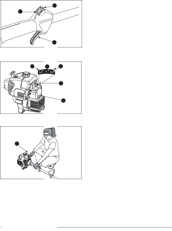
Fig. 4
4 |
6 |
|
7 |
|
8 |
Fig. 5
9
Fig. 6
Description of Parts – Figs. 4-7 |
|
|
|
1. |
Throttle Trigger |
6. |
Run Position (3) |
2. |
OFF (O) |
7. |
Choke Lever |
3. |
ON (I) |
8. |
Primer |
4. |
Full Choke Position (1) |
9. |
Starter Rope |
5. |
Partial Choke Position (2) |
|
|
Description des pièces – Figs. 4-7
1. |
Manette des gaz |
6. |
Position Marche (3) |
2. |
Arrét (O) |
7. |
Levier d'étrangleur |
3. |
Marche (I) |
8. |
Amorceur |
4. |
Étranglement |
9. |
Corde de démarrage |
|
maximum Position (1) |
|
|
5.Position d'étranglement partielle (2)
Beschreibung der Teile – Abb. 4-7 |
|
||
1. |
Gashebel |
6. |
Betriebsposition (3) |
2. |
Aus (O) |
7. |
Chokehebel |
3. |
Ein (I) |
8. |
Einspritzvorrichtung |
4. |
volle Chokeposition (1) |
9. |
Starterleine |
5.halbe Choke Zwischenposition (2)
Descrizione dei componenti - figg. 4-7
1. |
Leva acceleratore |
5. |
Posizione 2 (parziale) |
2. |
Arresto (O) |
6. |
Posiz. 3 (normale) |
3. |
Avivio (I) |
7. |
Leva starter |
4. |
Posizione 1 |
8. |
Innesco |
|
(massimo) |
9. |
Avvio a strappo |
|
|
Descrição das peças – Figuras 4-7 |
|
||
1. |
Gatilho do acelerador |
7. |
Posição de |
|
|
||
2. |
Parado (O) |
|
operação |
3. |
Funcionamento (I) |
8. |
Iniciador |
4. |
Posição de |
9. |
Corda de arranque |
|
estrangulamento total (1) |
10. |
Apoio para o pé |
|
|
||
5.Posição de estrangulamento parcial (2)
6.Posição de operação (3)
Descripción de piezas – Fig. 4-7 |
|
||
1. |
Gatillo del regulador |
6. |
Posición de marcha |
2. |
Apagado (O) |
|
(3) |
3. |
Encendido (I) |
7. |
Palanca del obturador |
4. |
Posición de obturación |
8. |
Cebador |
|
completa (1) |
9. |
Cuerda de arranque |
5. |
Posición de obturación |
10. |
Estribo |
|
parcial (2) |
|
|
6
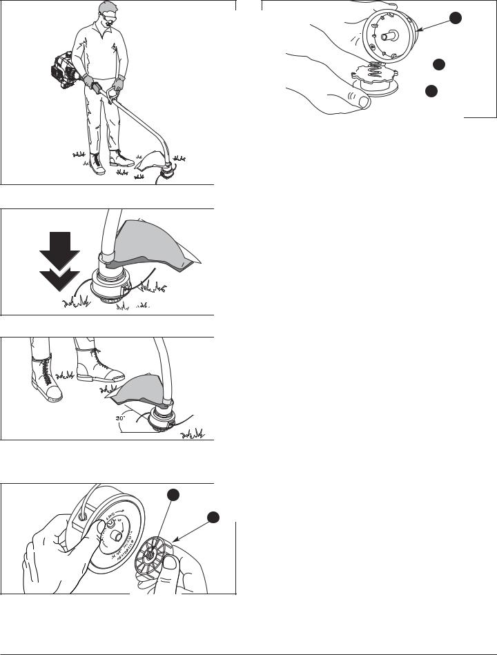
Fig. 7
Fig. 8
Fig. 9
1 |
2 |
Fig. 10
3

 4
4
 5
5
Fig. 11
Description of Parts – Figs. 10-11
1. |
Bolt |
4. |
Spring |
2. |
Bump Knob |
5. |
Inner Reel |
3. |
Outer Spool |
|
|
Description des pièces – Figs. 10-11 |
|||
1. |
Bouton |
3. |
Bobine extérieure |
2. |
Bouton de butée |
4. |
Ressort |
|
|
5. |
Moulinet intérieur |
Beschreibung der Teile – Abb. 10-11
1. |
Bolzen |
3. |
Spulengehäuse |
2. |
Auftippknopf |
4. |
Feder |
|
|
5. |
Spule |
Descrizione dei componenti – figg. 10-11 |
|||
1. |
Bullone |
4. |
Molla |
2. |
Bump Knob |
5. |
Rocchetto |
3. |
Bobina esterna |
|
|
Descrição das peças – Figuras 10-11 |
|||
1. |
Perno |
4. |
Mola |
2. |
Batente |
5. |
Carreto interior |
3. |
Bobina exterior |
|
|
Descripción de piezas – Fig. 10-11 |
|||
1. |
Perno |
4. |
Resorte |
2. |
Perilla percusiva |
5. |
Carrete interior |
3. |
Bobina exterior |
|
|
7

3
1
Fig. 16
Fig.
2
Fig. |
3 |
Fig. 14
4
Fig. 17
Fig. 18
Description of Parts – Figs. 12-18
1. |
Indexing Teeth |
3. |
Loop |
2. |
Slotted Holes |
4. |
Holding Slots |
Description des pièces – Figs. 12-18
1. |
Dents de |
3. |
Boucle |
|
Fig. 15 |
positionnement |
4. |
Fentes de retenue |
|
|
||||
2. |
Trous allongés |
|||
|
|
8
Beschreibung der Teile – Abb. 12-18
1. |
Schaltzähne |
3. |
Schlaufe |
2. |
Schlitzförmige |
4. |
Halteschlitze |
|
Löcher |
|
|
Descrizione dei componenti – figg. 12-18 |
|||
1. |
Dente |
3. |
Occhiello |
2. |
Asole |
4. |
Fessure di |
|
|
|
bloccaggio |
Descrição das peças – Figuras 12-18 |
|||
1. |
Dentes de encaixe |
3. |
Laço |
2. |
Fendas |
4. |
Fendas de retenção |
Descripción de piezas – Fig. 12-18
1. |
Dientes de posición |
3. |
Bucle |
2. |
Orificios ranurados |
4. |
Ranuras de retención |
1 
2 |
2 |
|
Fig. 19
3
Fig. 20
Fig. 21 |
Fig. 22 |
|
|
|
|
|
|
Fig. 23 |
Description of Parts – Figs. 19-23 |
||
1. |
Choke Lever |
3. Air Filter |
2. |
Screw |
|
Description des pièces – Figs. 19-23
1. |
Levier d'étrangleur |
3. Filtre à air |
2. |
Vis |
|
Beschreibung der Teile – Abb. 19-23
1. |
Chokehebel |
3. Luftfilter |
2. |
Schraube |
|
Descrizione dei componenti – figg. 19-23
1. |
Leva starter |
3. |
Filtro dell’aria |
2. |
Vite |
|
|
Descrição das peças – Figuras 19-23 |
|||
1. |
Alavanca do |
3. |
Filtro de ar |
|
estrangulador |
|
|
2. |
Parafuso |
|
|
Descripción de piezas – Fig. 19-23 |
|||
1. |
Palanca del |
3. |
Filtro de aire |
|
obturador |
|
|
2. |
Tornillo |
|
|
9
1
Fig. 24
2 
in.
mm.)
Fig. 25
Description of Parts – Figs. 24-25
|
1. |
Idle Speed Adjuster |
2. |
Spark Plug |
||||
|
|
|
|
|
Description des pièces – Figs. 24-25 |
|||
|
1. |
Vis de réglage du |
2. |
Bougie |
||||
|
|
|
|
|
|
ralenti |
|
|
|
|
|
|
|
Beschreibung der Teile – Abb. 24-25 |
|||
|
1. |
Lehrlaufdrehzahl- |
2. |
Zündkerze |
||||
|
|
|
|
|
|
regler |
|
|
|
|
|
|
|
Descrizione dei componenti – figg. 24-25 |
|||
|
1. |
Vite regime minimo |
2. |
Candela |
||||
|
|
|
|
|
Descrição das peças – Figuras 24-25 |
|||
|
|
|
|
|
||||
|
|
|
|
|
||||
|
|
|
|
|
||||
|
|
|
|
|||||
|
|
|
1. |
Regulador da |
2. |
Vela |
||
|
|
|||||||
|
|
|
|
|
|
velocidade lenta |
|
|
|
|
|
|
|
Descripción de piezas – Fig. 24-25 |
|||
|
1. |
Ajuste de marcha |
2. |
Bujía de encendido |
||||
|
|
|
|
|
|
lenta |
|
|
10
Enter all the information shown on the identification plate of your lawn scarifier into the box below.
The identification plate is located on the engine.
This information is very important for identifying any spare parts that are to be ordered at a later date, and for customer service.
SAFE OPERATING PRACTICES
USE THE UNIT CORRECTLY
This unit is intended exclusively:
–for use in accordance with the descriptions and safety instructions specified in this operating manual,
–for use in the garden,
–for trimming lawn edges and small or inaccessible grassy areas, e.g. under bushes),
–as well as for cutting rank weeds, shrubs and undergrowth.
This unit is not permitted for any other use. The user is liable for any injury to third parties
or damage to their property.
Operate the unit only in the delivered technical condition as stipulated by the manufacturer.
Any unauthorized changes to the unit will exempt the manufacturer from liability for any resulting damage or injuries.
SAFETY WARNINGS
READ ALL INSTRUCTIONS BEFORE OPERATING
•Read the operator’s manual carefully. Be thoroughly familiar with the controls and proper use of the unit. Know how to stop the unit.
•Never allow children to operate the unit. Never allow adults to operate the unit without proper instruction.
•Inspect the unit before use. Check for fuel leaks. Replace damaged parts. Make sure the cutting attachment is properly installed and securely fastened. Be sure the cutting attachment shield is properly attached, and positioned as recommended. Failure to do so can result in personal injury to the operator and bystanders, as well as damage to the unit.
•Use only 2.00 mm (0.080 inch) diameter genuine replacement line. Never use metal-reinforced line, wire, chain, or rope, etc. These can break off and become a dangerous projectile.
•Do not operate this unit when tired, ill, or under the influence of alcohol, drugs, or medication.
•Be aware of the risk of injury to the head, hands and feet.
•Clear the area to be cut before each use. Remove all objects such as rocks, broken glass, nails, wire, or string which can be thrown or become entangled in the cutting attachment.
•Clear the area of children, bystanders, and pets. At a minimum, keep all children, bystanders and pets outside a 15 m (50 ft.) radius; there still may be a risk to bystanders from thrown objects. Bystanders should wear eye protection. If you are approached, stop the engine and cutting attachment immediately.
SAFETY WARNINGS FOR PETROL TRIMMERS
WARNING: Petrol (Gasoline) is highly flammable, and its vapors can explode if ignited. Take the following precautions:
•Store fuel only in containers specifically designed and approved for the storage of such materials.
•Always stop the engine and allow it to cool before filling the fuel tank. Never remove the cap of the fuel tank, or add fuel, when the engine is hot.
•Mix and add fuel in a clean, well-ventilated area outdoors where there are no sparks or flames. Never fill fuel tank indoors. Slowly remove the fuel cap only after stopping engine. Do not smoke whilst fueling or mixing fuel. Wipe up any spilled fuel from the unit immediately.
11

SAFETY WARNINGS
WHILE OPERATING
•Never start or run the unit inside a closed room or building. Breathing exhaust fumes can kill. Operate this unit only in a well ventilated area outdoors.
•Wear safety glasses or goggles and ear/hearing protection when operating this unit. Wear safety glasses for all operations, i.e. preparation, operation and maintenance.
•Wear heavy, long pants, boots, gloves and long sleeve shirt. Do not wear, short pants, sandals or go barefoot.
•The cutting attachment guard must always be in place while operating. Do not operate unit without both trimming lines extended, and the proper line installed. Do not extend the trimming line beyond the length of the guard.
•The unit does not have a clutch and the cutting attachment continues rotating when the engine is idling.
•Adjust the D-handle to your size to provide the best grip.
•Be sure the cutting attachment is not in contact with anything before starting the unit.
•The operator and unit must be in a stable position while starting. See Fig. 6 and Starting/Stopping Instructions.
•Use the right tool. Only use this tool for the purpose intended.
•Do not touch the engine or muffler. These parts get extremely hot from operation. When turned off they remain hot for a short time.
•If you strike or become entangled with a foreign object, stop the engine immediately and check for damage. Do not operate before repairing damage. Do not operate the unit with loose or damaged parts.
•If the unit should start to vibrate abnormally, stop the engine and check immediately for the cause. Vibration is generally a warning of trouble.
•Stop and switch the engine to off for maintenance, repair, or for changing the cutting attachment or other attachments.
•Use only accessories and replacement parts approved by the manufacturer when servicing this unit. These parts are available from your authorized service dealer.
•Do not use parts, accessories or attachments not authorized for this unit. Doing so could lead to serious injury to the user, or damage to the unit, and void your warranty.
OTHER SAFETY WARNINGS
•Never store the unit, with fuel in the tank, inside a building where fumes may reach an open flame or spark.
•Allow the engine to cool before storing or transporting. Be sure to secure the unit while transporting.
•Clean after each use, see Cleaning and Storage instructions.
•Keep these instructions. Refer to them often and use them to instruct other users. If you loan someone this unit, also loan them these instructions.
•Have all repairs carried out by a specialist workshop only.
SAVE THESE INSTRUCTIONS
12
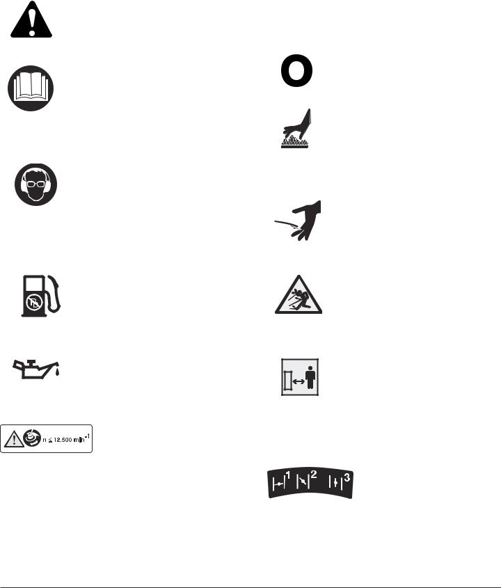
SAFETY AND INTERNATIONAL SYMBOLS
This operator's manual describes safety and international symbols and pictographs that may appear on this product. Read the operator's manual for complete safety, assembly, operating and maintenance and repair information.
SYMBOL |
MEANING |
SYMBOL |
MEANING |
||
|
• SAFETY ALERT SYMBOL |
|
|
|
• IGNITION SWITCH |
|
|
|
|
||
|
Indicates danger, warning, or |
|
|
|
ON / START / RUN |
|
caution. May be used in conjunction |
|
|
|
|
|
|
|
|
|
|
|
with other symbols or pictographs. |
|
|
|
|
•WARNING - READ OPERATOR'S MANUAL
Read the Operator’s Manual(s) and follow all warnings and safety instructions. Failure to do so can result in serious injury to the operator and/or bystanders.
•WEAR EYE AND HEARING PROTECTION
WARNING: Thrown objects and loud noise can cause severe eye injury and hearing loss. Wear eye protection meeting ANSI Z87.1-1989 standards and ear protection when operating this unit. Use a full face shield when needed.
•UNLEADED PETROL
Always use clean, fresh unleaded petrol.
•OIL
Refer to operator's manual for the proper type of oil.
• MAXIMUM RPM
Do not operate the unit faster than the maximum RPM.
•IGNITION SWITCH
OFF or STOP
•HOT SURFACE WARNING
Do not touch a hot muffler or cylinder. You may get burned. These parts get extremely hot from operation. When turned off they remain hot for a short time.
•SHARP BLADE
WARNING: Sharp blade on cutting attachment shield. To prevent serious injury, do not
touch line cutting blade.
•KEEP BYSTANDERS AWAY
WARNING: Keep all bystanders, especially children and pets, at least 15 meters (50 ft.)
from the operating area.
•THROWN OBJECTS CAN CAUSE SEVERE INJURY
WARNING: Keep clear of blower outlet. Never point the blower at yourself or others. Objects can be thrown from blower. Do not operate unit without proper attachments and guards in place.
• CHOKE CONTROL
1 • FULL choke position.
2 • PARTIAL choke position.
3 • RUN position.
13

ASSEMBLY INSTRUCTIONS
INSTALLING THE D-HANDLE
1.For your safety, the D-Handle must be assembled in front of the limiter sleeve. Push the D-Handle down over the shaft tube so that the handle slants back towards the engine (Fig. 1).
CAUTION: Do not force the D-handle over the limiter sleeve. Damage to the D-handle or unit may occur.
3. Install the bolt, washer, wing nut and tighten.
ADJUSTING THE D-HANDLE
1.Loosen the wing nut. It is not necessary to remove the wing nut, washer and bolt.
2.Rotate the D-handle to place the grip above the top of the shaft housing.
3.While holding the unit in the operating position (Fig. 7), position the D-handle to the location that provides you the best grip, and tighten the wing nut (Fig. 1).
INSTALLING THE CUTTING ATTACHMENT GUARD
1.Place the cutting attachment guard onto the shaft tube above the clamp assembly (Fig. 2).
2.Push the cutting attachment guard down to the top of the string head assembly and then rotate the cutting attachment guard until the screw holes align and the guard fits into the recessed pocket (Fig. 3).
OIL AND FUEL RECOMMENDATIONS
RECOMMENDED OIL TYPE
Use high quality oil formulated for use in 2-cycle, aircooled engines. Mix the oil according to the instructions on the 2-cycle engine oil container, 40:1 (2.5 %).
RECOMMENDED FUEL TYPE
Always use clean, fresh, unleaded petrol (gasoline).
OIL AND FUEL MIXING INSTRUCTIONS
Old and/or improperly mixed fuel are the main reasons for the unit not running properly. Be sure to use fresh, clean unleaded fuel. Follow the instructions carefully for the proper fuel/oil mixture.
Thoroughly mix the proper ratio of 2-cycle engine oil with unleaded petrol, 40:1 (2.5 %). Do not mix them directly in the tank.
OPERATING INSTRUCTIONS
STARTING INSTRUCTIONS
NOTE: Squeeze the throttle control until the engine has started and warmed up.
1.Mix petrol (gasoline) with oil. Fill fuel tank with fuel/oil mixture. See Oil and Fuel Mixing Instructions.
2.Put the ignition switch in the ON (I) position (Fig. 4).
3.TIP: When you are trying to start a unit that has been dormant for a while (or if it is brand new or difficult to start), be sure to press and release the primer bulb 20 times.
Fully press and release primer bulb slowly 10 times. You should feel and see fuel in the bulb (Fig. 5). If fuel hasn't entered the bulb, press three more times, or keep pressing until it does.
4. Place the choke lever in Position 1 (Fig. 5).
TIP: Make sure choke lever locks into (1) position.
5.With the unit on the ground, squeeze the throttle control and hold.
700: Pull starter rope briskly 3 times (Fig. 6).
710:Pull the starter rope out with a controlled and steady motion 3 times.
6.Place the choke lever in Position 2 (Fig. 5).
7.700: Pull starter rope briskly 1 to 3 times to start the engine (Fig. 6).
710:Pull the starter rope out with a controlled and steady motion 1 to 5 times to start the engine (Fig. 6).
14

OPERATING INSTRUCTIONS
NOTE: The unit uses Advanced Starting Technology™, which significantly reduces the effort required to start the engine. You must pull the starter rope out far enough to hear the engine attempt to start. There is no need to pull the rope briskly-- there is no harsh resistance when pulling. Be aware that this starting method is vastly different from (and much easier than) what you may be used to.
8.If the engine does not start, repeat steps 3 through 7.
9.Keep throttle trigger depressed to warm up engine. After the engine warms up for 10 to 15 seconds, place the choke lever in Position 3 (Fig. 18).
NOTE: If the engine floods while attempting to start, place the choke lever in the Position 3, squeeze the throttle trigger, and pull the starter rope briskly. The engine should start within three (3) to eight (8) pulls.
NOTE: Choking is not required when starting a warm engine. Start a warm engine with the ignition switch in the ON position and the choke lever in Position 2.
STOPPING INSTRUCTIONS
1.Release your finger from the throttle trigger (Fig. 4). Allow the engine to cool down by idling.
2.Put the ignition switch in the OFF (O) position (Fig. 4).
ADJUSTING TRIMMING LINE LENGTH
The Bump Head cutting attachment allows you to release trimming line without stopping the engine. To release more line, lightly tap the cutting attachment on the ground (Fig. 8) while operating the trimmer at high speed.
NOTE: Always keep the trimming line fully extended. Line release becomes more difficult as cutting line becomes shorter.
A blade in the cutting attachment guard will cut the line to the proper length if excess line is released. For best results, tap the Bump Head on bare ground or hard soil. If line release is attempted in tall grass, the engine may stall.
Some line breakage will occur from:
•Normal line fatigue
•Forcing the line into objects such as walls or fence posts
TIPS FOR BEST TRIMMING RESULTS
•Keep the cutting attachment parallel to the ground.
•Do not force the cutting attachment. Allow the tip of the line to do the cutting, especially along walls. Cutting with more than the tip will reduce cutting efficiency and may overload the engine.
•Cut grass over 200 mm (8 in.) by working from top to bottom in small increments to avoid premature line wear or engine drag.
•Cut from left to right whenever possible. Cutting to the right improves the unit's cutting efficiency. Clippings are thrown away from the operator.
•Slowly move the trimmer into and out of the cutting area at the desired height. Move either in a forwardbackward or side-to-side motion. Cutting shorter lengths produces the best results.
DECORATIVE TRIMMING
Decorative trimming is accomplished by removing all vegetation around trees, posts, fences, etc.
Rotate the whole unit so that the cutting attachment is at a 30° angle to the ground (Fig. 9).
MAINTENANCE AND REPAIR INSTRUCTIONS
LINE INSTALLATION
This section covers both Split-Line™ and standard single line installation.
Always use 2.0 mm. (0.080 in.) replacement line. The engine may overheat or fail if you use a line size other than specified.
There are two methods to replace the trimming line.
•Wind the inner reel with new line
•Install a prewound inner reel
Winding the Existing Inner Reel
1.Hold the outer spool with one hand and unscrew the Bump Knob counterclockwise (Fig. 10). Inspect the bolt inside the Bump Knob to make sure it moves freely. Replace the Bump Knob if damaged.
2.Remove the inner reel from the outer spool (Fig. 11).
3.Remove spring from the inner reel (Fig. 11).
4.Use a clean cloth to clean the the inner reel, spring, shaft, and inner surface of the outer spool
5.Check the indexing teeth on the inner reel and outer spool for wear (Fig. 12). If necessary, remove burrs or replace the reel and spool.
NOTE: Split-Line™ can only be used with the inner reel with the slotted holes. Single line can be used on either type of inner reel. Use figure 13 to identify the inner reel you have.
NOTE: Always use the correct line length when installing trimming line on the unit. The line may not release properly if the line is too long.
15

MAINTENANCE AND REPAIR INSTRUCTIONS
Single Line Installation
Go To Step 8 for Split-Line™ Installation
6.Take approximately 7.6 meters (25 ft.) of new trimming line, loop it into two equal lengths. Insert each end of the line through one of the two holes in the inner reel (Fig. 14). Pull the line through the inner reel so that the loop is as small as possible.
7.Wind the lines in tight even layers, onto the reel (Fig. 15). Wind the line in the direction indicated on the inner reel. Place your index finger between the two lines to stop the lines from overlapping. Do not overlap the ends of the line. Proceed to step 11.
Split-Line™ Installation
8.Take approximately 3.65 meters (12 ft.) of new trimming line. Insert one end of the line through one of the two holes in the inner reel (Fig. 16). Pull the line through the inner reel until only about 4 inches is left out.
9.Insert the end of the line into the open hole in the inner reel and pull the line tight to make the loop as small as possible (Fig. 16).
10.Before winding, split the line back about 6 inches.
11.Wind the line in tight even layers in the direction indicated on the inner reel.
NOTE: Failure to wind the line in the direction indicated will cause the cutting attachment to operate incorrectly.
12.Insert the ends of the line into the two holding slots (Fig. 17).
13.Insert the ends of the line through the eyelets in the outer spool and place inner reel with spring inside the outer spool (Fig. 18). Push the inner reel and outer spool together. While holding the inner reel and outer spool, grasp the ends and pull firmly to release the line from the holding slots in the reel.
NOTE: The spring must be assembled on the inner reel before reassembling the cutting attachment.
14.Hold the inner reel in place and install the Bump Knob by turning clockwise. Tighten securely.
Installing a Prewound Reel
1.Hold the outer spool with one hand and unscrew the Bump Knob counterclockwise (Fig. 10). Inspect the bolt inside the Bump Knob to make sure it moves freely. Replace the Bump Knob if damaged.
2.Remove the old inner reel from the outer spool (Fig. 11).
3.Remove the spring from the old inner reel (Fig. 11).
4.Use a clean cloth to clean the the inner reel, spring, shaft, and inner surface of the outer spool.
5.Place the spring in the new inner reel.
NOTE: The spring must be assembled on the inner reel before reassembling the cutting attachment.
6.Insert the ends of the line through the eyelets in the outer spool (Fig. 18).
7.Place the new inner reel inside the outer spool. Push the inner reel and outer spool together. While holding the inner reel and outer spool, grasp the ends and pull firmly to release the line from the holding slots in the spool.
8.Hold the inner reel in place and install the Bump Knob by turning clockwise. Tighten securely.
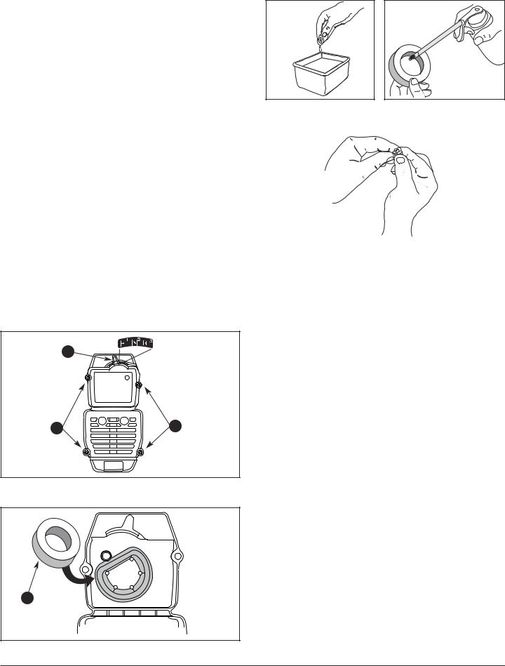
AIR FILTER MAINTENANCE
Removing the Air Filter/Muffler Cover
1. Place the choke lever in the position 2.
NOTE: The choke lever must be in position 2 (Fig. 19) to remove the air filter/muffler cover.
2.Remove the four (4) screws securing the air filter/muffler cover (Fig. 19). Use a flat blade or T-20 Torx bit screwdriver.
3.Pull the cover from the engine. Do not force.
Cleaning the Air Filter
Clean and re-oil the air filter every 10 hours of operation. It is an important item to maintain. Failure to maintain your air filter properly can result in poor performance or can cause permanent damage to your engine.
1.Remove the air filter/muffler cover. See Removing the Air filter/Muffler Cover.
2.Remove the air filter from inside the air filter/muffler cover (Fig. 20).
3.Wash the filter in detergent and water (Fig. 21). Rinse the filter thoroughly. Squeeze out excess water. Allow it to dry completely.
4.Apply enough clean oil to lightly coat the filter (Fig. 22).
5.Squeeze the filter to spread and remove excess oil.
6.Replace the air filter inside the air filter/muffler cover (Fig. 20).
NOTE: Operating the unit without the air filter and air filter/muffler cover assembly, will VOID the warranty.
Reinstalling the Air Filter/Muffler Cover
1.Place the air filter/muffler cover over the back of the carburetor and muffler.
NOTE: The choke lever must be in position 2 (Fig. 19) to install the air filter/muffler cover.
2.Insert the four (4) screws into the holes in the air filter/muffler cover (Fig. 19) and tighten. Use a T-20 Torx bit screwdriver. Do not over tighten. Do not force.
Check Fuel Mixture
Old and/or improperly mixed fuel is usually the reason for the unit not running properly. Drain and refill the tank with fresh, properly mixed fuel prior to making any adjustments.
16

MAINTENANCE AND REPAIR INSTRUCTIONS
Clean Air Filter
The condition of the air filter is important to the operation of the unit. A dirty air filter will restrict air flow and change the air/fuel mixture. This is often mistaken for an out of adjustment carburetor. Check the condition of the air filter before adjusting the idle speed screw. Refer to Air Filter Maintenance.
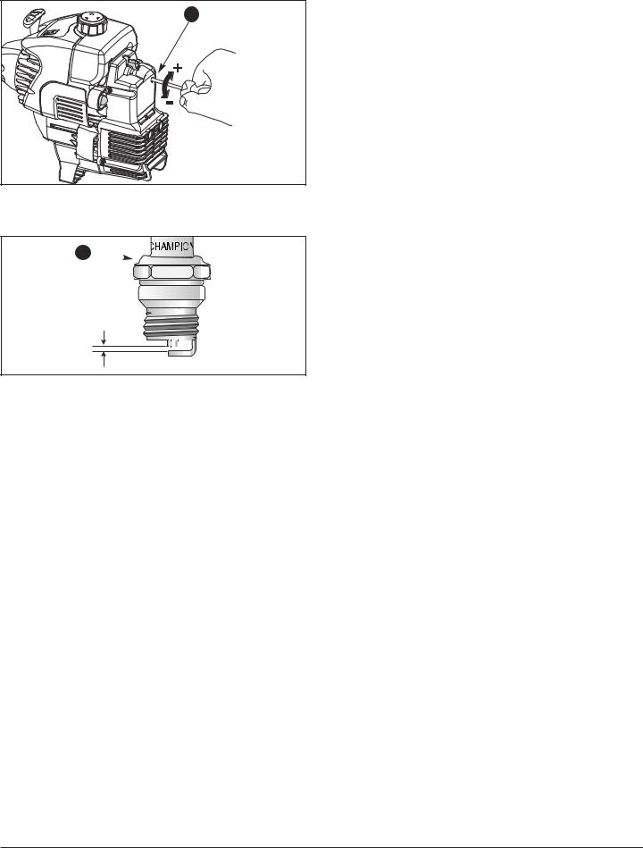
Adjust Idle Speed Adjuster
If after checking the fuel mixture and cleaning the air filter the engine
still will not idle, adjust the idle speed adjuster as follows.
1.Start the engine and let it run about 2–3 minutes at a high speed (full throttle) to warm up.
2.Release the throttle trigger and let the engine idle. If the engine stops, insert a small phillips screwdriver into the hole in the air filter/muffler cover (Fig. 23).
Turn the idle speed adjuster in, clockwise, 1/8 of a turn at a time (as needed) until the engine idles smoothly. See Specifications for idle RPM.
NOTE: The unit does not have a clutch and the cutting attachment continues rotating when the engine is idling.
3.To reduce the idle speed, turn the idle speed adjuster counterclockwise 1/8 of a turn at a time (as needed).
Checking the fuel mixture, cleaning the air filter, and adjusting the idle
speed screw should solve most engine problems. If not and:
•The engine will not idle,
•The engine hesitates or stalls on acceleration,
•There is a loss of engine power,
Have the carburetor adjusted by an authorized service dealer.
REPLACING THE SPARK PLUG
Use a Champion RDJ7Y spark plug (or equivalent). The correct air gap is 0.5 mm (0.020 in.). Remove the plug after every 50 hours of operation and check its condition.
1.Stop the engine and allow it to cool. Grasp the plug wire firmly and pull the cap from the spark plug.
2.Clean dirt from around the spark plug.
3.Replace cracked, fouled or dirty spark plug. Set the air gap at 0.5 mm (0.020 in.) using a feeler gauge (Fig. 24).
4.Install a correctly gapped spark plug in the cylinder head. Tighten by turning the 5/8 in. socket clockwise until snug.
Do not over tighten.
CLEANING
Use a small brush to clean off the outside of the unit. Do not use strong detergents. Household cleaners that contain aromatic oils
such as pine and lemon, and solvents such as kerosene, can damage plastic housing or handle. Wipe off any moisture with a soft cloth.
STORAGE
•Never store the unit with fuel in the tank where fumes may reach an open flame or spark.
•Allow the engine to cool before storing.
•Store the unit in a dry place, locked up or up-high to prevent
unauthorized use or damage. Keep out of the reach of children.
LONG TERM STORAGE
If the unit will be stored for an extended time, use the following storage procedure.
1.Drain all fuel from the fuel tank and drain into a container with the same 2-cycle fuel mixture. Do not use fuel that has been stored for more than 60 days.
2.Start the engine and allow it to run until it stalls. This ensures that all fuel has been drained from the carburetor.
3.Allow the engine to cool. Remove the spark plug and put 30 ml (1 oz.) of any high quality motor oil or 2- cycle oil into the cylinder. Pull the starter rope slowly to distribute the oil. Reinstall the spark plug.
NOTE: Remove the spark plug and drain all of the oil from the cylinder before attempting to start the trimmer after storage.
4.Thoroughly clean the unit and inspect for any loose or damaged parts. Repair or replace damaged parts and tighten loose screws, nuts or bolts. The unit is ready for storage.
5Store the unit in a dry place, locked up or up-high to prevent unauthorized use or damage. Keep out of the reach of children.
17

TROUBLESHOOTING |
|
|
|
ENGINE WILL NOT START |
|
C A U S E |
A C T I O N |
Empty fuel tank |
Fill fuel tank with properly mixed fuel |
Primer bulb wasn't pressed enough |
Press primer bulb fully and slowly 10 times |
Engine is flooded |
Squeeze the trigger and pull the starter rope |
|
(with choke in Position 3) |
Old or improperly mixed fuel |
Drain fuel tank and add fresh fuel mixture |
Fouled spark plug |
Replace or clean the spark plug |
|
|
ENGINE WILL NOT IDLE / LOW IDLE SPEED |
|
C A U S E |
A C T I O N |
Air filter is plugged |
Replace or clean the air filter |
Old or improperly mixed fuel |
Drain fuel tank and add fresh fuel mixture |
Improper carburetor adjustment |
Adjust according to the Carburetor Adjustments section |
|
|
ENGINE WILL NOT ACCELERATE |
|
C A U S E |
A C T I O N |
Old or improperly mixed fuel |
Drain fuel tank and add fresh fuel mixture |
Improper carburetor adjustment |
Take to an authorized service dealer for an adjustment |
Cutting attachment bound with grass |
Stop the engine and clean the cutting attachment |
Dirty air filter |
Clean or replace the air filter |
|
|
ENGINE LACKS POWER OR STALLS WHEN CUTTING |
|
C A U S E |
A C T I O N |
Old or improperly mixed fuel |
Drain fuel tank and add fresh fuel mixture |
Improper carburetor adjustment |
Take to an authorized service dealer for an adjustment |
Fouled spark plug |
Replace or clean the spark plug |
|
|
CUTTING ATTACHMENT WILL NOT ADVANCE LINE |
|
C A U S E |
A C T I O N |
Cutting attachment bound with grass |
Stop the engine and clean cutting attachment |
Cutting attachment out of line |
Refill with new line |
Inner reel bound up |
Rewind /replace the inner reel |
Cutting head dirty |
Clean inner reel and outer spool |
Line welded |
Disassemble, remove the welded section and rewind |
Line twisted when refilled |
Disassemble and rewind the line |
Not enough line is exposed |
Push the bump knob and pull out line until 4 inches |
|
(102 mm) of line is outside of the cutting attachment |
|
|
If further assistance is required, contact your local authorized service dealer.
All information, illustrations, and specifications in this manual are based on the latest product information available at the time of printing. We reserve the right to make any changes at any time without notice.
18

SPECIFICATIONS
ENGINE
Engine Type........................................................................................................................................... |
Air-Cooled, 2-Cycle |
Ignition Type.......................................................................................................................................................... |
Electronic |
Displacement........................................................................................................................................... |
31 cm3 (1.9 cu. in.) |
Maximum Engine Performance in accordance with ISO 8893.......................................................................... |
75 kw (1 hp) |
Idle RPM...................................................................................................................................................... |
3200 min-1 (rpm) |
Operating RPM............................................................................................................................................ |
7700 min-1 (rpm) |
Fuel.......................................................................................................................................... |
Fuel/Oil Mixture (40:1) 2,5 % |
Ignition Switch ............................................................................................................................................... |
Rocker On/Off |
Starter............................................................................................................................................................... |
Auto Rewind |
Fuel Tank Capacity........................................................................................................................................ |
355 ml (15 oz.) |
DRIVE SHAFT & CUTTING HEAD
Drive Shaft Housing ............................................................................................................................................. |
Steel Tube |
Throttle Control ........................................................................................................................................ |
Finger-Tip Trigger |
Cutting Head.......................................................................................................................................... |
Bump Line Release |
Trimming Line Diameter............................................................................................................... |
2 mm (0.080 in.), dual line |
Cutting Path Diameter.................................................................................................................................. |
381 mm (15 in.) |
Mass (without fuel).......................................................................................................................................... |
4.5 kg (10 lbs) |
ACCESSORIES on request |
|
GUARANTEE
The guarantee conditions that apply in each country are published by either our company or the importer of our products. Faults will be repaired free of charge within the framework of the guarantee, provided that they have been caused by a material defect or manufacturing error. In the case of a guarantee repair, please contact your dealer or our nearest branch office.
19

20
Reportez dans l'encadré ci-dessous toutes les indications figurant sur la plaquette signalétique qui se trouve à proximité du moteur de l'appareil.
Les indications qu'elle contient sont d'une importance capitale car elles permettront plus tard de déterminer les pièces de rechange et d'accomplir les prestations de service après-vente.
POUR VOTRE SECURITE
UTILISATION CONFORME DE L’APPAREIL
Cet appareil est exclusivement destiné à servir
–conformément aux descriptions et consignes de sécurité fournies dans la présente notice d'instructions
–dans le jardin domestique et le jardin d'agrément,
–pour tondre les bordures gazonnées et les surfaces herbeuses restreintes ou difficiles d'accès (par ex. sous les buissons)
–ainsi que pour couper les pousses sauvages, les buissons et les broussailles.
Toute utilisation sortant de ce cadre sera réputée non conforme. Tout dommage envers un tiers et ses biens est à la charge de l'utilisateur.
N'utilisez l'appareil que dans l'état technique où vous l'avez acheté et tel que prescrit par le fabricant.
Toute modification volontaire de l'appareil exclut toute responsabilité du fabricant envers les dommages qui pourraient en résulter.
AVERTISSEMENTS DE SÉCURITÉ
LISEZ TOUTES LES INSTRUCTIONS AVANT L’UTILISATION
•Veuillez lire le manuel de l'utilisateur soigneusement. Familiarisez-vous très bien avec les commandes et l'utilisation correcte de l’appareil. Sachez comment arrêter l’appareil.
•Ne laissez pas les enfants faire fonctionner l’ appareil. Ne laissez jamais des adultes actionner l’appareil sans formation préalable.
•Inspectez l'appareil avant utilisation. Remplacez les pièces endommagées. Regardez s'il y a des fuites de carburant. Assurez-vous que les fixations sont solidement en place. Remplacez les pièces de l'accessoire de coupe qui sont fendillées, ébréchées ou endommagées. Assurez-vous que l'accessoire de coupe est correctement installé et solidement fixé. Assurez-vous que le protecteur d'accessoire de coupe est correctement fixé et positionné comme recommandé. Vous risquez sinon de causer des blessures à l'opérateur et aux spectateurs, et d'endommager l'appareil.
•N'utilisez que du fil de remplacement d'origine de 2,03 mm (0,080 po) de diamètre. N'utilisez jamais de fil ou de cordon à renfort métallique, etc. Car il peut se briser et se transformer en projectile dangereux.
•N'utilisez pas l'appareil si vous êtes fatigué, malade ou sous l'effet de l'alcool, de drogues ou de médicaments.
•Attention aux risques de blessure à la tête, aux mains et aux pieds.
•Dégagez la zone de coupe avant chaque usage. Enlevez tous les objets pouvant être projetés ou happés par l'accessoire : cailloux, verre brisé, clous, fil ou ficelle.
•Éloignez enfants, spectateurs et animaux de la zone. Tenez-les à au moins 15 m (50 pi) de là mais sachez que les spectateurs risquent quand même d'être atteints par des objets projetés. Les spectateurs doivent porter des protections oculaires. Arrêtez immédiatement le moteur et l'accessoire si quelqu'un s'approche de vous.
CONSIGNES DE SECURITE
ATTENTION : L’essence est hautement inflammable et les vapeurs d’essence peuvent exploser en cas de contact avec une flamme. Prenez les précautions suivantes :
•Stockez toujours le carburant dans des conteneurs spécialement conçus et agréés pour le stockage de ce type de produit.
•Arrêtez toujours le moteur et laissez-le refroidir avant de remplir le réservoir. Vous ne devez jamais enlever le bouchon du réservoir ou ajouter du carburant tant que le moteur est chaud.
21

AVERTISSEMENTS DE SÉCURITÉ
•Mélangez et ajoutez le carburant dans un lieu extérieur, aéré et propre, à l'abri d’étincelles ou de flammes. Ne remplissez jamais le réservoir de carburant à l'intérieur. Retirez lentement le bouchon du réservoir, seulement après avoir arrêté le moteur. Ne fumez pas pendant le remplissage ou le mélange de carburant. Essuyez immédiatement tout déversement de carburant.
PENDANT L’UTILISATION
•Ne démarrez et n’utilisez jamais l’appareil dans une pièce ou un bâtiment fermé. L’inhalation des fumées d’échappement peut être mortelle. N’utilisez cet appareil qu’en extérieur, dans une zone bien ventilée.
•Portez des lunettes de sécurité et des protège-oreilles lorsque vous faites marcher l'appareil. Portez des lunettes de sécurité pour toutes les activités, ex. préparation, fonctionnement, entretien.
•Portez des pantalons épais et longs, des bottes, des gants et une chemise à manches longues. Ne marchez pas pieds nus et évitez les pantalons courts et les sandales.
•Le carter de protection de coupe doit toujours être en place lorsque l’appareil est utilisé. La longueur du fil de coupe ne doit pas dépasser celle du carter de protection.
•L'appareil n'est pas muni d'un accouplement et, lorsque le moteur tourne à vide, la bobine de fil continue de tourner.
•Réglez la poignée en D à votre taille afin d’assurer la meilleure prise en main possible.
•Assurez-vous que la bobine de fil n’est en contact avec aucun objet avant de mettre l’appareil en marche.
•L’utilisateur et l’appareil doivent être en position stable lors du démarrage. Reportez-vous à la Figure 6 et aux Instructions pour le démarrage/l’arrêt.
•Utilisez l’outil approprié. N’utilisez cet outil que pour l’usage auquel il est destiné.
•Ne touchez pas le moteur et le pot d’échappement. Ces éléments chauffent énormément lorsque l’appareil est en fonctionnement. Une fois qu’il est arrêté, ils restent chauds pendant un court moment.
•Ne faites pas tourner le moteur à vitesse élevée lorsque vous n’effectuez pas de coupe.
•En cas de contact avec un corps étranger, arrêtez le moteur immédiatement et vérifiez que l’appareil n’est pas endommagé. N’utilisez pas l’appareil avant de l’avoir remis en état. N’utilisez pas l’appareil si certaines pièces sont mal serrées ou endommagées.
•Si l’appareil se met à vibrer de manière anormale, arrêtez le moteur et procédez immédiatement à une vérification. Les vibrations indiquent généralement la présence d’un problème.
•Coupez le moteur et mettez-le en position Arrêt pour toute opération d’entretien ou de maintenance et lors du changement de la bobine de fil ou d’un autre accessoire.
•Utilisez uniquement des accessoires et des pièces de rechange homologués par le fabricant pour l'entretien. Elles sont disponibles auprès de votre concessionnaire agréé.
•N'utilisez pas de pièces ou accessoires non autorisés pour cet appareil. Cela pourrait causer des blessures graves ou endommager l'appareil et annuler la garantie.
AUTRES CONSIGNES DE SECURITE
•S’il y a du carburant dans le réservoir, n’entreposez jamais l’appareil dans un bâtiment où les vapeurs pourraient entrer en contact avec une flamme nue ou une étincelle.
•Laissez le moteur refroidir avant de ranger ou de transporter l’appareil. Veillez à protéger l’appareil pour le transport.
•Nettoyez l’appareil après chaque utilisation ; reportezvous aux instructions de la section «Nettoyage et entreposage».
•Conservez ce manuel. Reportez-vous souvent aux instructions qu’il comporte et transmettez ces instructions aux autres utilisateurs. Si vous prêtez cet appareil, prêtez également ces instructions.
•Confiez toutes les réparations exclusivement à un atelier spécialisé.
CONSERVEZ CES INSTRUCTIONS
22
 Loading...