


214-381-000
Table of contents
 Loading...
OWNERS
MANUAL
.75
CHaIn DRIVE
TILLERS
ASSEMBLY
OPERATION
MAINTENANCE
PARTS LIST
Model Numbers
214-381-000
214-385-000
Important:
Read Safety Rules and
Instructions Carefully
PRINTED IN U.S.A.
Thank you for purchasing an
American built product.
FORM NO. 770-3193

INDEX
Safe Operation Practices
......................................
3
Assembly Instructions
...........................................
4
Operation............................................................... 8
How to Use Your Tiller
...........................................
8
Adjustments..........................................................11
Lubrication............................................................11
Maintenance..........................................................11
Off-Season Storage...............................................13
Trouble Shooting Chart
........................................
14
Illustrated Parts
................................................
16, 18
Parts Lists.........................................................17, 19
Parts for Chain Case........................................20,21
Parts Information....................................Back Cover
r
♦
♦
♦
♦
♦
♦
♦
♦
♦
♦
♦
♦
♦
♦
V
LIMITED WARRANTY
For one year from the date of original retail purchase, MTD PRODUCTS INC will either
repair or replace, at its option, free of charge, F.O.B. factory or authorized service firm, any
part or parts found to be defective i ^ material or workmanship. Transportation charges for
the movement of any power equipment unit or attachment are the responsibility of the pur
chaser. Transportation charges for any parts submitted for replacement under this warran
ty must be paid by the purchaser un ess such return is requested by MTD PRODUCTS INC.
This warranty will not apply to any eart which has become inoperative due to misuse, ex
cessive use, accident, neglect, improper maintenance, alterations, or unless the unit has
been operated and maintained in ac cordance with the instructions furnished. This warran
ty does not apply to the engine, motor, battery, battery chargeror component parts thereof.
Please refer to the applicable manufacturer’s warranty on these items.
This warranty will not apply where the unit has been used commercially.
Warranty service is available through your local authorized service dealer or distributor. If
you do not know the dealer or distri 3utor in your area, please write to the Customer Service
Department of MTD.
The return of a complete unit will r ot be accepted by the factory unless prior written per
mission has been extended by MT D.
This warranty gives you specific legal rights. You may also have other rights which vary
from state to state.
♦
♦
♦
♦
♦
♦
t
♦
♦
♦
♦
♦
♦
(E)
WARNING
This unit is equipped with an internal combustion engine and should not be used on or near any unim
proved forest-covered, brush-covered or grass-covered land unless the engine’s exhaust system is
equipped with a spark arrester meeting ap )licable local or state laws (if any). If a spark arrester is used, it
should be maintained in effective working order by the operator.
In the State of California the above is required by law (Section 4442 of the California Public Resources
Code). Other states may have similar laws. Federal laws apply on federal lands. A spark arrester muffler is
available at your nearest engine authorized service center.

I WARNING \
To reduce the potential for any injury, comply with the following safety instructions. Failure to comply with
the instructions may result in personal injury.
SAFE OPERATION PRACTICES FOR TILLERS
1. It is suggested that this manual be read in its
entirety before attempting to assemble or
operate this unit. Keep this manual in a safe
place for future reference and for ordering
replacement parts.
2. Your tiller is a precision piece of power equip
ment, not a plaything. Therefore, exercise ex
treme caution at all times.
3. Read this Owner’s Manual carefully. Be
thoroughly familiar with the controls and the
proper use of the equipment.
14. Check the fuel before starting the engine.
Gasoline is an extremely flammable fuel. Do
not fill gasoline tank indoors, when the engine
is running, or while the engine is still hot.
Wipe off any spilled gasoline before starting
the engine as it may cause a fire or explosion.
15. Do not run the engine while indoors. Exhaust
gases are deadly poisonous.
16. Be careful not to touch the muffler after the
engine has been running. It is hot.
4. Never allow children to operate a power tiller.
Only persons well acquainted with these rules
of safe operation should be allowed to use
your tiller.
5. Keep the area of operation clear of all per
sons, particularly small children and pets.
6. Do not operate equipment when barefoot or
wearing open sandals. Always wear substan
tial footwear.
7. Do not wear loose fitting clothing that could
get caught on the tiller.
8. Do not start the engine unless the shift lever
is in the neutral (N) position.
9. Do not stand in front of the tiller while starting
the engine.
10. Do not place, feet and hands on or near the
tines when starting the engine or while the
engine is running.
11. Never attempt to make a wheel or depth bar
adjustment while the engine is running.
17. Do not change the engine governor settings
or overspeed the engine. Excessive engine
speeds are dangerous.
18. Before any maintenance work is performed or
adjustments are made, remove the spark plug
wire and ground it on the engine block for
added safety.
19. Use caution when tilling near buildings and
fences. Rotating tines can cause damage or
injury.
20. Before attempting to remove rocks, bricks and
other objects from tines, stop the engine and
be sure the tines have stopped completely.
Disconnect the spark plug wire and ground to
prevent accidental starting.
21. Check the tine and engine mounting bolts at
frequent intervals for proper tightness.
22. Keep all nuts, bolts and screws tight to be
sure the equipment is in safe working condi
tion.
12. Do not leave the tiller unattended with
engine running.
the
13. Do not walk in front of the tiller while the
engine is running.
23. Never store the equipment with gasoline in
the tank inside of a building where fumes may
reach an open flame or spark. Allow the
engine to cool before storing in any
enclosure.
a
•m
P
Tailpiece
Handle
— Pane
Assem )ly
Control
-Rod
De )th
B ir
FIGURE 1.
f:) £ I
M-
K-*-0l=:3)
't
FIGURE 2.
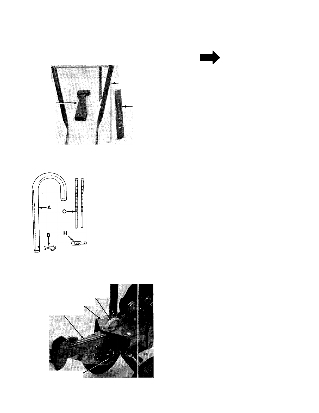
“U” Clevis
Pin (A)
Frame
Tailpiece
Cotter Pin (B)
FIGURE 3.
ASSEMBLY
INSTRUCTIONS
NOTE
This unit is shipped WiTHOUT GAS-
OLiNE or OiL. After assembiy, see
separate engine manuai for proper
fuei and engine oii recommenda
tions.
Before any step is undertaken, the instructions for
that step shouid be read thoroughiy.
Tools Required:
(2) 9/16" Sockets, open or box wrench
-Loose Parts in Carton: (See Figure 1)
Handle Panel Assembly
Depth Bar
Ta.lpiece
Control Rod
Hardware Pack (Not Shown)
-Contents of Hardware Pack: (See Figure 2)
A
B
C
D
E
F
G
H
I
K
L
M (2)
N (2)
O (2)
P
Q
(1) “U”-Clevis Pin .50" Dia.
(1) Internal Cotter Pin
(2) Cable Ties
(2) Hex Bolts 3/8-16 x 1.00" Lg.
(2) Belleville Washers 3/8" I.D.
(2) Lock Washers 3/8" I.D.
(2) Hex Nuts 3/8-16 Thd.
(1) Ferrule
(2) Hairpin Cotters
(1) Clevis Pin
(1) Spring Pin
Carriage Bolts
Lock Washers 5/16" I.D.
Hex Nuts 5/16-18 Thd.
(2) Clevis Pins (385 Only—Not Shown)
(2) Cotter Pins (385 Only—Not Shown)
TAILPIECE INSTALLATION
Slide the tailpiece into the frame. Secure with
-“U”-clevis pin (A) and cotter pin (B). See figure 3.

Depth Bar
Spring
Pin (L)
DEPTH BAR iNSTALLATiON
Slide the depth bar into the tailpiece to desired
depth. Secure with clevis pin (K) and spring pin (L).
■See figure 4.
FIGURE 4.
HANDLE ASSEMBLY
1. Secure handle panel to handles by placing
carriage bolts (M) through the lower holes in
the handle panel and through the handles.
Secure with lock washers (N) and hex nuts (O),
finger tight only.
2. Remove hex bolt and belleville washer from
-----
each side of frame as shown in figure 5.
FIGURE 5.
Hex Bolt (D)
3. Place the handle panel assembly in position
against the frame.
4. Start the hex bolt and belleville washer (re
moved in step 1) by hand in the bottom hole in
handle. See figure 6.
5. Select height position for the handle by lining
up one of the holes in the handle with desired
hole in frame. See figure 5.
6. Place belleville washer (E) on hex bolt (D), and
insert hex bolt through handle and frame.
Secure with lock washer (F) and hex nut (G) on
inside of frame. See figure 6.
7. Tighten all nuts and bolts securely.
FIGURE 6.
NOTE
The clutch rod must be readjusted
whenever the handle height is
changed.
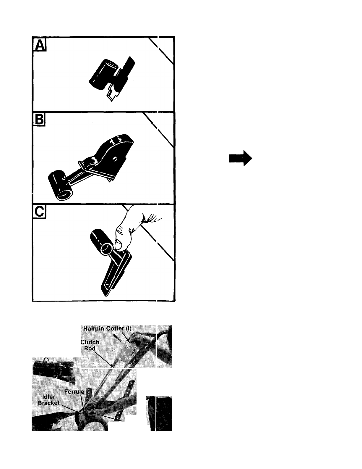
THROTTLE CONTROL ASSEMBLY
Assemble the throttle control to the handle panel
as follows.
, 1. Hold the throttle control assembly beneath
the handle panel. Turn the control sideways
and insert the lever up through the wide por
tion of the siot on the handle panel. See figure
------
7A.
After the end of the lever is through the slot,
turn and then tip the control forward as shown
-in figure 7B to slide it through the slot.
NOTE
The lever must be all the way to the
back of the control housing as
shown in figure 7B.
3. Push the control back into the slot in the han
dle panel and press in place. Be certain the
—control is locked securely into the slot.
4. Secure throttle control cable to handle with
cable ties (C). Cut off excess ends.
FIGURE 7.
K - Hairpin
Cotter (I)
CLUTCH CONTROL ROD INSTALLATION
1. Place shift lever (located on handle panel) in
neutral (N) position, Piace bent end of control
rod into shift lever. Secure with hairpin cotter
-----
(I). See figure 8.
2. Thread ferrule (H) onto the other end of con
trol rod so that the ferrule lines up with the
hole in idler bracket. Secure with hairpin cot
ter (I). See figure 8.
FIGURE 8.
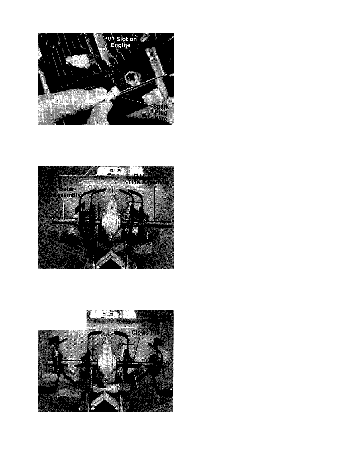
3. Disconnect the spark plug wire from spark
plug to prevent accidental starting. Secure
end of spark plug wire in the “V” slot on the
— engine. See figure 9. With the clutch lever in
neutral position, pull starter cord several
times. The tines should not turn. If they do,
remove the hairpin cotter and remove the con
trol rod from the clutch lever. Thread the con
trol rod in or out of the ferrule as necessary.
Replace and check again for correct adjust
ment.
FIGURE 9.
TINE ASSEMBLIES
Model 381 Only
Check to be certain the tine assemblies are on the
tine shaft so that the sharp edge enters the soil
first. See figure 11.
Model 385 Only
The inner tine assembiies are instaiied at the fac
tory. The outer tine assemblies are inverted. See
-figure 10. The right hand outer tine assembly has
been removed, inverted and slid onto the left hand
side for shipping only. The same has been done
with the left hand outer tine assembly.
FIGURE 10.
- J Ï-WÏW A ..W '*i
Remove both outer tines. Place tine removed from
left hand side on right hand shaft. Place tine
removed from right hand side on left hand shaft.
Make sure that the sharp edge of the tines enters
the soil first. Secure with clevis pins (P) and inter-
■ nal cotter pins (Q). See figure 11.
FIGURE 11.
Loading...