


DRM002/D M68HC08M6
8HC08M68HC 08M68HC08M
USB08 Universal Serial Bus
Evaluation Board
Using the MC68HC908JB8
Designer Reference Manual

USB08 Universal Serial Bus
Evaluation Board
Using the MC68HC908JB8
By: Dipl.-Ing. Oliver Thamm
MCT Elektronikladen GbR
Hohe Str. 9-13
04107 Leipzig
Germany
Telephone: |
+49 (0)341 2118354 |
Fax: |
+49 (0)341 2118355 |
Email: |
mct@elektronikladen.de |
Web: |
http://www.elektronikladen.de/mct |
Motorola and |
are registered trademarks of Motorola, Inc. |
|
DigitalDNA is a trademark of Motorola, Inc. |
© Motorola, Inc., 2001 |
|
USB08 Evaluation Board |
Designer Reference Manual |
|
|
|
|
|
|
|
MOTOROLA |
|
3 |

Designer Reference Manual
Motorola reserves the right to make changes without further notice to any products herein. Motorola makes no warranty, representation or guarantee regarding the suitability of its products for any particular purpose, nor does Motorola assume any liability arising out of the application or use of any product or circuit, and specifically disclaims any and all liability, including without limitation consequential or incidental damages. "Typical" parameters which may be provided in Motorola data sheets and/or specifications can and do vary in different applications and actual performance may vary over time. All operating parameters, including "Typicals" must be validated for each customer application by customer’s technical experts. Motorola does not convey any license under its patent rights nor the rights of others. Motorola products are not designed, intended, or authorized for use as components in systems intended for surgical implant into the body, or other applications intended to support or sustain life, or for any other application in which the failure of the Motorola product could create a situation where personal injury or death may occur. Should Buyer purchase or use Motorola products for any such unintended or unauthorized application, Buyer shall indemnify and hold Motorola and its officers, employees, subsidiaries, affiliates, and distributors harmless against all claims, costs, damages, and expenses, and reasonable attorney fees arising out of, directly or indirectly, any claim of personal injury or death associated with such unintended or unauthorized use, even if such claim alleges that Motorola was negligent regarding the design or manufacture of the part. Motorola, Inc. is an Equal Opportunity/Affirmative Action Employer.
Designer Reference Manual |
USB08 Evaluation Board |
|
|
4 |
MOTOROLA |

Designer Reference Manual — USB08 Evaluation Board
List of Sections
Section 1. USB08 Quick Start . . . . . . . . . . . . . . . . . . . . . 17
Section 2. Hardware Description . . . . . . . . . . . . . . . . . . . 27
Section 3. Software Module Descriptions. . . . . . . . . . . . 43
Section 4. Universal Serial Bus (USB) Interface . . . . . . 59
Appendix A. Supported Standard
Device Requests . . . . . . . . . . . . . . . . . . . . . 81
Appendix B. USB08 Descriptors . . . . . . . . . . . . . . . . . . . 83
Appendix C. Source Code Files . . . . . . . . . . . . . . . . . . . . 89
Appendix D. Bill of Materials and Schematic . . . . . . . . 127
Appendix E. Universal USB Device
Driver (USBIO) . . . . . . . . . . . . . . . . . . . . . . 131
USB08 Evaluation Board |
|
Designer Reference Manual |
|
|
|
MOTOROLA |
List of Sections |
5 |

List of Sections
Designer Reference Manual |
|
USB08 Evaluation Board |
|
|
|
6 |
List of Sections |
MOTOROLA |

Designer Reference Manual — USB08 Evaluation Board
Table of Contents
Section 1. USB08 Quick Start
1.1 Contents . . . . . . . . . . . . . . . . . . . . . . . . . . . . . . . . . . . . . . . . . .17
1.2 Introduction . . . . . . . . . . . . . . . . . . . . . . . . . . . . . . . . . . . . . . . .17
1.3 Required System Configuration . . . . . . . . . . . . . . . . . . . . . . . .17
1.4 Connecting the Demo Board to the PC . . . . . . . . . . . . . . . . . .18
1.5 Driver Installation . . . . . . . . . . . . . . . . . . . . . . . . . . . . . . . . . . .19
1.6 Starting the Windows Demo Application. . . . . . . . . . . . . . . . . .24
Section 2. Hardware Description
2.1 Contents . . . . . . . . . . . . . . . . . . . . . . . . . . . . . . . . . . . . . . . . . .27
2.2 Introduction . . . . . . . . . . . . . . . . . . . . . . . . . . . . . . . . . . . . . . . .27
2.3 Technical Data . . . . . . . . . . . . . . . . . . . . . . . . . . . . . . . . . . . . .28
2.3.1 MC68HC908JB8 Microcontroller . . . . . . . . . . . . . . . . . . . . .28
2.3.2 USB08 Evaluation Board . . . . . . . . . . . . . . . . . . . . . . . . . . .29
2.4 Circuit Description. . . . . . . . . . . . . . . . . . . . . . . . . . . . . . . . . . .30
2.4.1 MCU Core Circuit and USB Interface. . . . . . . . . . . . . . . . . .31
2.4.2 Input/Output Functions . . . . . . . . . . . . . . . . . . . . . . . . . . . . .32
2.4.3 Monitor Mode Interface . . . . . . . . . . . . . . . . . . . . . . . . . . . .33
2.4.4 User RS232 Port . . . . . . . . . . . . . . . . . . . . . . . . . . . . . . . . .35
2.4.5 Power Supply . . . . . . . . . . . . . . . . . . . . . . . . . . . . . . . . . . . .36
2.5 Board Layout . . . . . . . . . . . . . . . . . . . . . . . . . . . . . . . . . . . . . .36
2.6 Jumpers and Bridges . . . . . . . . . . . . . . . . . . . . . . . . . . . . . . . .38
USB08 Evaluation Board |
|
Designer Reference Manual |
|
|
|
MOTOROLA |
Table of Contents |
7 |

Table of Contents
2.7 Connectors . . . . . . . . . . . . . . . . . . . . . . . . . . . . . . . . . . . . . . . .40
2.7.1 Expansion Connector X1 . . . . . . . . . . . . . . . . . . . . . . . . . . .40
2.7.2 Monitor Mode Connector X2 . . . . . . . . . . . . . . . . . . . . . . . .40
2.7.3 User RS232 Connector X3. . . . . . . . . . . . . . . . . . . . . . . . . .41
2.8 Memory Map. . . . . . . . . . . . . . . . . . . . . . . . . . . . . . . . . . . . . . .41
Section 3. Software Module Descriptions
3.1 Contents . . . . . . . . . . . . . . . . . . . . . . . . . . . . . . . . . . . . . . . . . .43
3.2 Introduction . . . . . . . . . . . . . . . . . . . . . . . . . . . . . . . . . . . . . . . .43
3.3 General Structure of the M68HC08 Firmware . . . . . . . . . . . . .44
3.4 How to Build the Compiler Project . . . . . . . . . . . . . . . . . . . . . .45 3.5 Main Module U08MAIN.C . . . . . . . . . . . . . . . . . . . . . . . . . . . . .48 3.6 Interrupt and Reset Vector Module VECJB8.C. . . . . . . . . . . . .49 3.7 C Startup Module CRTSJB8.S . . . . . . . . . . . . . . . . . . . . . . . . .50 3.8 Push Button Module U08KEY.C . . . . . . . . . . . . . . . . . . . . . . . .50 3.9 LED Control with U08LED.H. . . . . . . . . . . . . . . . . . . . . . . . . . .52 3.10 Software ADC Module U08ADC.C . . . . . . . . . . . . . . . . . . . . . .52 3.11 RS232 Communication Module U08232.C. . . . . . . . . . . . . . . .54 3.12 USB Communication Module U08USB.C . . . . . . . . . . . . . . . . .56 3.13 Compiler Specific Adjustments . . . . . . . . . . . . . . . . . . . . . . . . .57
Section 4. Universal Serial Bus (USB) Interface
4.1 Contents . . . . . . . . . . . . . . . . . . . . . . . . . . . . . . . . . . . . . . . . . .59
4.2 Introduction . . . . . . . . . . . . . . . . . . . . . . . . . . . . . . . . . . . . . . . .59
4.3 Characteristics of the USB08 Reference Design . . . . . . . . . . .60
4.4 USB Basics. . . . . . . . . . . . . . . . . . . . . . . . . . . . . . . . . . . . . . . .62
Designer Reference Manual |
|
USB08 Evaluation Board |
|
|
|
8 |
Table of Contents |
MOTOROLA |
Table of Contents
4.5 USB Implementation in the Reference Design . . . . . . . . . . . . .65
4.5.1 Activation of the USB Module. . . . . . . . . . . . . . . . . . . . . . . .65
4.5.2 Endpoint Configuration. . . . . . . . . . . . . . . . . . . . . . . . . . . . .65
4.5.3 USB Reset . . . . . . . . . . . . . . . . . . . . . . . . . . . . . . . . . . . . . .67
4.6 Device Management with Endpoint 0 . . . . . . . . . . . . . . . . . . . .69
4.6.1 Enumeration . . . . . . . . . . . . . . . . . . . . . . . . . . . . . . . . . . . . .69
4.6.2 Assignment of the Device Address . . . . . . . . . . . . . . . . . . .69 4.6.3 Requesting Descriptors . . . . . . . . . . . . . . . . . . . . . . . . . . . .72
4.6.4 Device Configuration . . . . . . . . . . . . . . . . . . . . . . . . . . . . . .74
4.6.5 STALL Condition . . . . . . . . . . . . . . . . . . . . . . . . . . . . . . . . .74
4.7 Data Communication via Endpoints EP1 and EP2 . . . . . . . . . .75
4.7.1 Receiving Data . . . . . . . . . . . . . . . . . . . . . . . . . . . . . . . . . . .76
4.7.2 Transmission of Data . . . . . . . . . . . . . . . . . . . . . . . . . . . . . .76
4.8 Host Interaction: Vendor ID and Product ID . . . . . . . . . . . . . . .78
4.9 Windows Device Driver. . . . . . . . . . . . . . . . . . . . . . . . . . . . . . .78
Appendix A. Supported Standard Device Requests
Supported Standard Device Requests . . . . . . . . . . . . . . . . . . .81
Appendix B. USB08 Descriptors
B.1 Contents . . . . . . . . . . . . . . . . . . . . . . . . . . . . . . . . . . . . . . . . . .83
B.2 Introduction . . . . . . . . . . . . . . . . . . . . . . . . . . . . . . . . . . . . . . . .83
B.3 Device Descriptor . . . . . . . . . . . . . . . . . . . . . . . . . . . . . . . . . . .84
B.4 Configuration Descriptor . . . . . . . . . . . . . . . . . . . . . . . . . . . . . .84
B.5 Interface Descriptor . . . . . . . . . . . . . . . . . . . . . . . . . . . . . . . . .85
B.6 Endpoint 1 Descriptor . . . . . . . . . . . . . . . . . . . . . . . . . . . . . . . .85
B.7 Endpoint 2 Descriptor . . . . . . . . . . . . . . . . . . . . . . . . . . . . . . . .85
B.8 String Descriptors . . . . . . . . . . . . . . . . . . . . . . . . . . . . . . . . . . .86
USB08 Evaluation Board |
|
Designer Reference Manual |
|
|
|
MOTOROLA |
Table of Contents |
9 |

Table of Contents
Appendix C. Source Code Files
C.1 Contents . . . . . . . . . . . . . . . . . . . . . . . . . . . . . . . . . . . . . . . . . .89
HC908JB8.H . . . . . . . . . . . . . . . . . . . . . . . . . . . . . . . . . . . .90
U08USB.H . . . . . . . . . . . . . . . . . . . . . . . . . . . . . . . . . . . . . .93
U08232.H . . . . . . . . . . . . . . . . . . . . . . . . . . . . . . . . . . . . . .96
U08LED.H . . . . . . . . . . . . . . . . . . . . . . . . . . . . . . . . . . . . . .96
U08MAIN.C . . . . . . . . . . . . . . . . . . . . . . . . . . . . . . . . . . . . .97
U08DESC.C . . . . . . . . . . . . . . . . . . . . . . . . . . . . . . . . . . .100
U08USB.C . . . . . . . . . . . . . . . . . . . . . . . . . . . . . . . . . . . . .104
U08232.C . . . . . . . . . . . . . . . . . . . . . . . . . . . . . . . . . . . . .113
U08KEY.C . . . . . . . . . . . . . . . . . . . . . . . . . . . . . . . . . . . . .116
U08ADC.C . . . . . . . . . . . . . . . . . . . . . . . . . . . . . . . . . . . . .117
VECJB8.C . . . . . . . . . . . . . . . . . . . . . . . . . . . . . . . . . . . . .119
CRTSJB8.S . . . . . . . . . . . . . . . . . . . . . . . . . . . . . . . . . . . .120
USB08.LKF . . . . . . . . . . . . . . . . . . . . . . . . . . . . . . . . . . . .121
BUILD.BAT . . . . . . . . . . . . . . . . . . . . . . . . . . . . . . . . . . . .121
USB08.MAP . . . . . . . . . . . . . . . . . . . . . . . . . . . . . . . . . . .122
USB08.S19 . . . . . . . . . . . . . . . . . . . . . . . . . . . . . . . . . . . .125
Appendix D. Bill of Materials and Schematic
Bill of Materials and Schematic. . . . . . . . . . . . . . . . . . . . . . . .127
Appendix E. Universal USB Device Driver (USBIO)
E.1 Contents . . . . . . . . . . . . . . . . . . . . . . . . . . . . . . . . . . . . . . . . .132
E.2 Introduction . . . . . . . . . . . . . . . . . . . . . . . . . . . . . . . . . . . . . . .135
E.3 Overview. . . . . . . . . . . . . . . . . . . . . . . . . . . . . . . . . . . . . . . . .135
E.3.1 Platforms . . . . . . . . . . . . . . . . . . . . . . . . . . . . . . . . . . . . . .136
E.3.2 Features . . . . . . . . . . . . . . . . . . . . . . . . . . . . . . . . . . . . . . .136
E.4 Architecture. . . . . . . . . . . . . . . . . . . . . . . . . . . . . . . . . . . . . . .138
E.4.1 USBIO Object Model . . . . . . . . . . . . . . . . . . . . . . . . . . . . .140
E.4.1.1 USBIO Device Objects. . . . . . . . . . . . . . . . . . . . . . . . . .140
E.4.1.2 USBIO Pipe Objects . . . . . . . . . . . . . . . . . . . . . . . . . . .142
E.4.2 Establishing a Connection to the Device . . . . . . . . . . . . . .144
E.4.3 Power Management . . . . . . . . . . . . . . . . . . . . . . . . . . . . . .146
Designer Reference Manual |
|
USB08 Evaluation Board |
|
|
|
10 |
Table of Contents |
MOTOROLA |
Table of Contents
E.4.4 Device State Change Notifications. . . . . . . . . . . . . . . . . . .148
E.5 Programming Interface . . . . . . . . . . . . . . . . . . . . . . . . . . . . . .149
E.5.1 Programming Interface Overview. . . . . . . . . . . . . . . . . . . .149
E.5.2 Control Requests . . . . . . . . . . . . . . . . . . . . . . . . . . . . . . . .150
E.5.3 Data Transfer Requests . . . . . . . . . . . . . . . . . . . . . . . . . . .182
E.5.3.1 Bulk and Interrupt Transfers . . . . . . . . . . . . . . . . . . . . .182
E.5.3.2 Isochronous Transfers . . . . . . . . . . . . . . . . . . . . . . . . . .184
E.5.4 Input and Output Structures . . . . . . . . . . . . . . . . . . . . . . . .185
E.5.5 Enumeration Types . . . . . . . . . . . . . . . . . . . . . . . . . . . . . .214
E.5.6 Error Codes . . . . . . . . . . . . . . . . . . . . . . . . . . . . . . . . . . . .218
E.6 USBIO Class Library. . . . . . . . . . . . . . . . . . . . . . . . . . . . . . . .220
E.6.1 CUsbIo Class . . . . . . . . . . . . . . . . . . . . . . . . . . . . . . . . . . .220
E.6.2 CUsbIoPipe Class . . . . . . . . . . . . . . . . . . . . . . . . . . . . . . .221
E.6.3 CUsbIoThread Class . . . . . . . . . . . . . . . . . . . . . . . . . . . . .222
E.6.4 CUsbIoReaderClass. . . . . . . . . . . . . . . . . . . . . . . . . . . . . .222
E.6.5 CUsbIoWriter Class . . . . . . . . . . . . . . . . . . . . . . . . . . . . . .222
E.6.6 CUsbIoBufClass . . . . . . . . . . . . . . . . . . . . . . . . . . . . . . . . .223
E.6.7 CUsbIoBufPool Class. . . . . . . . . . . . . . . . . . . . . . . . . . . . .223
E.7 USBIO Demo Application . . . . . . . . . . . . . . . . . . . . . . . . . . . .223
E.7.1 Dialog Pages for Device Operations . . . . . . . . . . . . . . . . .224 E.7.1.1 Device . . . . . . . . . . . . . . . . . . . . . . . . . . . . . . . . . . . . . .224
E.7.1.2 Descriptors . . . . . . . . . . . . . . . . . . . . . . . . . . . . . . . . . . .224
E.7.1.3 Configuration . . . . . . . . . . . . . . . . . . . . . . . . . . . . . . . . .225 E.7.1.4 Interface . . . . . . . . . . . . . . . . . . . . . . . . . . . . . . . . . . . . .225
E.7.1.5 Pipes . . . . . . . . . . . . . . . . . . . . . . . . . . . . . . . . . . . . . . .225
E.7.1.6 Class or Vendor Request . . . . . . . . . . . . . . . . . . . . . . . .226
E.7.1.7 Feature. . . . . . . . . . . . . . . . . . . . . . . . . . . . . . . . . . . . . .226 E.7.1.8 Other . . . . . . . . . . . . . . . . . . . . . . . . . . . . . . . . . . . . . . .226 E.7.1.9 Dialog Pages for Pipe Operations . . . . . . . . . . . . . . . . .227 E.7.1.10 Pipe . . . . . . . . . . . . . . . . . . . . . . . . . . . . . . . . . . . . . . . .227 E.7.1.11 Buffers . . . . . . . . . . . . . . . . . . . . . . . . . . . . . . . . . . . . . .227 E.7.1.12 Control . . . . . . . . . . . . . . . . . . . . . . . . . . . . . . . . . . . . . .228 E.7.1.13 Read from Pipe to Output Window . . . . . . . . . . . . . . . .228 E.7.1.14 Read from Pipe to File . . . . . . . . . . . . . . . . . . . . . . . . . .228
E.7.1.15 Write from File to Pipe . . . . . . . . . . . . . . . . . . . . . . . . . .229
USB08 Evaluation Board |
|
Designer Reference Manual |
|
|
|
MOTOROLA |
Table of Contents |
11 |

Table of Contents
E.8 Installation Issues . . . . . . . . . . . . . . . . . . . . . . . . . . . . . . . . . .229
E.8.1 Automated Installation: The USBIO Installation Wizard . . .229
E.8.2 Manual Installation: The USBIO Setup Information File. . .232
E.8.3 Uninstalling USBIO. . . . . . . . . . . . . . . . . . . . . . . . . . . . . . .236
E.8.4 Building a Customized Driver Setup. . . . . . . . . . . . . . . . . .237
E.9 Registry Entries . . . . . . . . . . . . . . . . . . . . . . . . . . . . . . . . . . .239
E.10 Related Documents . . . . . . . . . . . . . . . . . . . . . . . . . . . . . . . .241
E.11 Light Version Limitations. . . . . . . . . . . . . . . . . . . . . . . . . . . . .241
Designer Reference Manual |
|
USB08 Evaluation Board |
|
|
|
12 |
Table of Contents |
MOTOROLA |

Designer Reference Manual — USB08 Evaluation Board
List of Figures
Figure |
Title |
Page |
1-1 Demo Board Connected to the USB Hub . . . . . . . . . . . . . . . . .18 1-2 Found New Hardware Screen . . . . . . . . . . . . . . . . . . . . . . . . .19
1-3 Found New Hardware Wizard Start Screen . . . . . . . . . . . . . . .20
1-4 Locate Driver Files Screen . . . . . . . . . . . . . . . . . . . . . . . . . . . .21
1-5 Driver Files Search Results Screen . . . . . . . . . . . . . . . . . . . . .22
1-6 Found New Hardware Wizard Finish Screen . . . . . . . . . . . . . .23 1-7 Windows Demo Application IO08USB . . . . . . . . . . . . . . . . . . .24
1-8 Driver Entry for USB08 in the Device Manager Window . . . . .25
2-1 USB08 Evaluation Board . . . . . . . . . . . . . . . . . . . . . . . . . . . . .30
2-2 PCB Component Side Layout Plan. . . . . . . . . . . . . . . . . . . . . .37
2-3 Detailed Layout Plan. . . . . . . . . . . . . . . . . . . . . . . . . . . . . . . . .37 2-4 Solder Bridge Placement on Downside of the PCB . . . . . . . . .39
3-1 Structure and Dependencies of the Firmware Files . . . . . . . . .45 3-2 Measurement of Resistor Values Using a Digital Input . . . . . .52
4-1 USB Address Register (UADDR) . . . . . . . . . . . . . . . . . . . . . . .65 4-2 USB Control Register 3 (UCR3) . . . . . . . . . . . . . . . . . . . . . . . .66
4-3 USB Interrupt Register 0 (UIR0) . . . . . . . . . . . . . . . . . . . . . . . .68 4-4 USB Control Register 0 (UCR0) . . . . . . . . . . . . . . . . . . . . . . . .68 4-5 USB Interrupt Register 1 (UIR1) . . . . . . . . . . . . . . . . . . . . . . . .69 4-6 USB Status Register 0 (USR0). . . . . . . . . . . . . . . . . . . . . . . . .70 4-7 USB Control Register 0 (UCR0) . . . . . . . . . . . . . . . . . . . . . . . .71 4-8 USB Address Register (UADDR) . . . . . . . . . . . . . . . . . . . . . . .72 4-9 USB Interrupt Register 1 (UIR1) . . . . . . . . . . . . . . . . . . . . . . . .75 4-10 USB Status Register 1 (USR1). . . . . . . . . . . . . . . . . . . . . . . . .76 4-11 USB Control Register 1 (UCR1) . . . . . . . . . . . . . . . . . . . . . . . .77
USB08 Evaluation Board |
|
Designer Reference Manual |
|
|
|
MOTOROLA |
List of Figures |
13 |

List of Figures
Figure |
Title |
Page |
D-1 USB08 Evaluation Board Schematic . . . . . . . . . . . . . . . . . . .129
E-1 USB Driver Stack . . . . . . . . . . . . . . . . . . . . . . . . . . . . . . . . . .138
E-2 USBIO Device and Pipe Objects Example . . . . . . . . . . . . . . .143
E-3 Layout of an Isochronous Transfer Buffer . . . . . . . . . . . . . . .183
E-4 USBIO Class Library. . . . . . . . . . . . . . . . . . . . . . . . . . . . . . . .220
Designer Reference Manual |
|
USB08 Evaluation Board |
|
|
|
14 |
List of Figures |
MOTOROLA |

Designer Reference Manual — USB08 Evaluation Board
List of Tables
Table |
Title |
Page |
2-1 Port A Monitor Mode Entry Levels . . . . . . . . . . . . . . . . . . . . . .33
2-2 Monitor Mode Cable Pin Configuration. . . . . . . . . . . . . . . . . . .34
2-3 Jumper Configuration . . . . . . . . . . . . . . . . . . . . . . . . . . . . . . . .38
2-4 Solder Bridges Configuration . . . . . . . . . . . . . . . . . . . . . . . . . .39
2-5 MC68HC908JB8 Memory Map. . . . . . . . . . . . . . . . . . . . . . . . .41
3-1 Memory Utilization . . . . . . . . . . . . . . . . . . . . . . . . . . . . . . . . . .47
4-1 Low-Speed USB Packet Types . . . . . . . . . . . . . . . . . . . . . . . .62
4-2 MC68HC908JB8 Endpoint Configuration . . . . . . . . . . . . . . . . .66
D-1 Bill of Materials for USB08 V 1.01 . . . . . . . . . . . . . . . . . . . . . |
128 |
E-1 I/O Operations Supported by the USBIO Device Driver . . . . .149
E-2 Error Codes Defined by the USBIO Device Driver . . . . . . . . .218
E-3 Registry Parameters Supported by the USBIO Driver . . . . . .239
USB08 Evaluation Board |
|
Designer Reference Manual |
|
|
|
MOTOROLA |
List of Tables |
15 |

List of Tables
Designer Reference Manual |
|
USB08 Evaluation Board |
|
|
|
16 |
List of Tables |
MOTOROLA |

Designer Reference Manual — USB08 Evaluation Board
Section 1. USB08 Quick Start
1.1 Contents
1.2 Introduction . . . . . . . . . . . . . . . . . . . . . . . . . . . . . . . . . . . . . . . .17
1.3 Required System Configuration . . . . . . . . . . . . . . . . . . . . . . . .17
1.4 Connecting the Demo Board to the PC . . . . . . . . . . . . . . . . . .18
1.5 Driver Installation . . . . . . . . . . . . . . . . . . . . . . . . . . . . . . . . . . .19
1.6 Starting the Windows Demo Application. . . . . . . . . . . . . . . . . .24
1.2 Introduction
This section describes the connection and startup of the USB08
(universal serial bus) evaluation board demo application. The main component of the USB08 is the Motorola MC68HC908JB8 8-bit microcontroller (MCU).
1.3 Required System Configuration
To connect the USB08, you will need a personal computer (PC) with one of the following Microsoft® operating systems:
• |
Windows® 98 |
• |
Windows ME |
• |
Windows 2000 Professional |
NOTE: |
Ensure that the PC has the necessary hardware (universal serial bus |
||
|
(USB) host controller and USB root hub) and that the necessary system |
||
|
drivers are installed. |
|
|
|
|
|
|
|
Microsoft and Windows are registered trademarks of Microsoft Corporation in the United States |
||
|
and/or other countries. |
|
|
USB08 Evaluation Board |
|
|
Designer Reference Manual |
|
|
|
|
|
|
|
|
MOTOROLA |
USB08 Quick Start |
17 |
|

USB08 Quick Start
1.4 Connecting the Demo Board to the PC
Since low-speed USB devices should be equipped with a captive connection, the USB cable is fixed on the USB08 board (downstream direction). In the upstream direction (PC/host side), the USB connections are always type A. Therefore, the cable of the USB08 demo board has a type A plug.
The connection of the demo board is made directly to the USB socket of the PC or, as shown in the Figure 1-1, to a USB hub.
Figure 1-1. Demo Board Connected to the USB Hub
The board supply current can be delivered by the USB connection.
Therefore, the jumper JP2, which is directly beside the USB cable, has to be in the position Bus Powered. The jumper JP1-A (jumper block, highest position) must be opened, which corresponds to the default shipping configuration.
Designer Reference Manual |
|
USB08 Evaluation Board |
|
|
|
18 |
USB08 Quick Start |
MOTOROLA |

USB08 Quick Start
Driver Installation
1.5 Driver Installation
For this example, the installation of the driver software is described using the Windows 2000 operating system. The installation using Windows 98 (second edition) looks quite similar.
After the electrical connection of the demo board, the Windows operating system recognizes the presence of a new hardware component and shows the message Found New Hardware.
Figure 1-2. Found New Hardware Screen
USB08 Evaluation Board |
|
Designer Reference Manual |
|
|
|
MOTOROLA |
USB08 Quick Start |
19 |
USB08 Quick Start
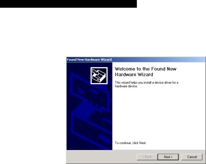
The hardware assistant, Figure 1-3, now tries to find the suitable driver information for the USB08 evaluation board. Click the Next button.
NOTE: The installation using the Windows 2000 operating system requires administrator rights.
Figure 1-3. Found New Hardware Wizard Start Screen
Designer Reference Manual |
|
USB08 Evaluation Board |
|
|
|
20 |
USB08 Quick Start |
MOTOROLA |
USB08 Quick Start
Driver Installation
Insert the USB08 product CD into the CD-ROM drive and mark the appropriate check box CD-ROM drives as shown in Figure 1-4. Click the Next button.
Figure 1-4. Locate Driver Files Screen
USB08 Evaluation Board |
|
Designer Reference Manual |
|
|
|
MOTOROLA |
USB08 Quick Start |
21 |
USB08 Quick Start
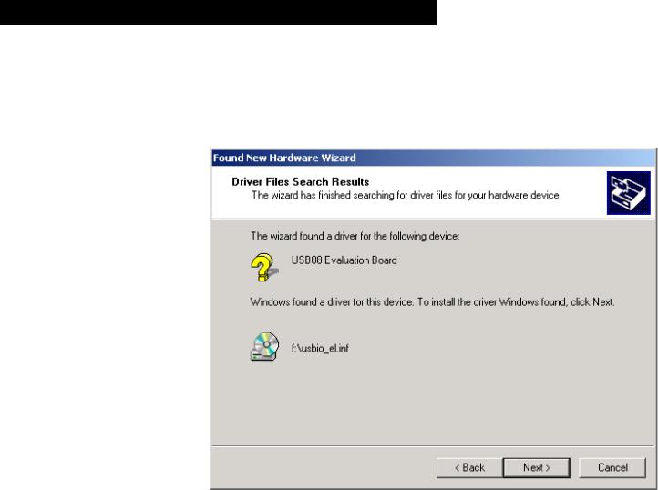
As shown in Figure 1-5, the hardware assistant will find the driver information file usbio_el.inf in the root directory of the CD ROM. Confirm this selection by clicking Next.
Figure 1-5. Driver Files Search Results Screen
Designer Reference Manual |
|
USB08 Evaluation Board |
|
|
|
22 |
USB08 Quick Start |
MOTOROLA |
USB08 Quick Start
Driver Installation
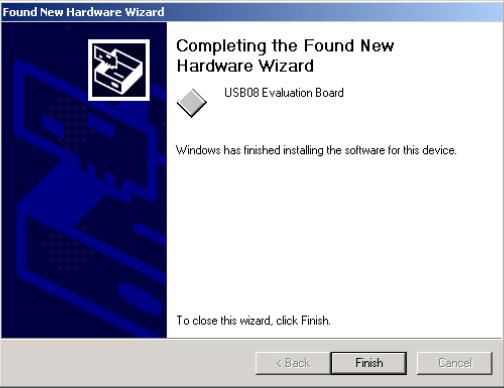
The Windows operating system now copies the INF file and the driver file usbio_el.sys to the appropriate Windows directories. After clicking
Finish (Figure 1-6), the driver installation will be completed and the USB device will be ready for use.
Figure 1-6. Found New Hardware Wizard Finish Screen
NOTE: The installation does not require a restart of the computer, since this is a true Plug & Play installation.
USB08 Evaluation Board |
|
Designer Reference Manual |
|
|
|
MOTOROLA |
USB08 Quick Start |
23 |
USB08 Quick Start
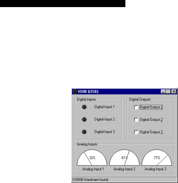
1.6 Starting the Windows Demo Application
The windows demo application:
•Shows the measured values and push button information coming from the demo board
•Allows the controlling of the demo board light-emitting diodes
(LED)
The demo application is located in the root directory of the USB08 product CD. The file name of the demo application is IO08USB.EXE. This program can be started directly from the CD.
Figure 1-7. Windows Demo Application IO08USB
As shown in Figure 1-7, the bottom line of the application window shows the status of the connection established to the USB08 demo board. The LED symbols on the left upper side of the application window can be switched on or off by pressing the keys of the USB08 demo board.
Designer Reference Manual |
|
USB08 Evaluation Board |
|
|
|
24 |
USB08 Quick Start |
MOTOROLA |
USB08 Quick Start
Starting the Windows Demo Application
By setting the check boxes on the upper right side it is possible to switch on or off the LEDs of the demo board. The needle pointer instruments on the lower side of the application window indicate the measured values of the three variable resistors:
•Input 1 represents the photo sensor.
•Input 2 shows the thermistor value.
•Input 3 can be varied using the turnable regulator.
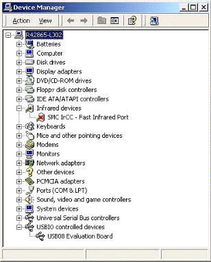
The USB08 evaluation board can be disconnected from the USB port and reconnected at any time, because the drivers are automatically activated or deactivated by the Windows operating system. The activation/deactivation of the drivers can be watched in the operating system’s device manager window (start button/settings/control panel/ system/device manager). The catalog entry USBIO controlled devices and the device entry USB08 Evaluation Board are visible only if the hardware is present. See Figure 1-8.
Figure 1-8. Driver Entry for USB08 in the Device Manager Window
USB08 Evaluation Board |
|
Designer Reference Manual |
|
|
|
MOTOROLA |
USB08 Quick Start |
25 |

USB08 Quick Start
The Windows demo application, IO08USB.EXE, must be re-started in the case of a hardware connection interrupt. This is because an automatic resynchronization (though it would be possible) was not implemented here. The demo application is arranged as simply and as understandable as possible.
Designer Reference Manual |
|
USB08 Evaluation Board |
|
|
|
26 |
USB08 Quick Start |
MOTOROLA |

Designer Reference Manual — USB08 Evaluation Board
Section 2. Hardware Description
2.1 Contents
2.2 Introduction . . . . . . . . . . . . . . . . . . . . . . . . . . . . . . . . . . . . . . . .27
2.3 Technical Data . . . . . . . . . . . . . . . . . . . . . . . . . . . . . . . . . . . . .28
2.3.1 MC68HC908JB8 Microcontroller . . . . . . . . . . . . . . . . . . . . .28
2.3.2 USB08 Evaluation Board . . . . . . . . . . . . . . . . . . . . . . . . . . .29
2.4 Circuit Description. . . . . . . . . . . . . . . . . . . . . . . . . . . . . . . . . . .30
2.4.1 MCU Core Circuit and USB Interface. . . . . . . . . . . . . . . . . .31
2.4.2 Input/Output Functions . . . . . . . . . . . . . . . . . . . . . . . . . . . . .32
2.4.3 Monitor Mode Interface . . . . . . . . . . . . . . . . . . . . . . . . . . . .33
2.4.4 User RS232 Port . . . . . . . . . . . . . . . . . . . . . . . . . . . . . . . . .35
2.4.5 Power Supply . . . . . . . . . . . . . . . . . . . . . . . . . . . . . . . . . . . .36
2.5 Board Layout . . . . . . . . . . . . . . . . . . . . . . . . . . . . . . . . . . . . . .36
2.6 Jumpers and Bridges . . . . . . . . . . . . . . . . . . . . . . . . . . . . . . . .38
2.7 Connectors . . . . . . . . . . . . . . . . . . . . . . . . . . . . . . . . . . . . . . . .40
2.7.1 Expansion Connector X1 . . . . . . . . . . . . . . . . . . . . . . . . . . .40
2.7.2 Monitor Mode Connector X2 . . . . . . . . . . . . . . . . . . . . . . . .40
2.7.3 User RS232 Connector X3. . . . . . . . . . . . . . . . . . . . . . . . . .41
2.8 Memory Map. . . . . . . . . . . . . . . . . . . . . . . . . . . . . . . . . . . . . . .41
2.2 Introduction
The USB08 evaluation board is the hardware platform for the universal serial bus (USB) reference design. The board serves the provided demo application, which is contained in the integrated FLASH memory of the M68HC08 microcontroller (MCU).
USB08 Evaluation Board |
|
Designer Reference Manual |
|
|
|
MOTOROLA |
Hardware Description |
27 |

Hardware Description
Beyond that, the USB08 enables the implementation and testing of its own M68HC08 software for evaluation purposes. For that purpose, the board contains a monitor mode interface for reprogramming and debugging. The monitor mode interface of the USB08 is compatible with
Motorola development tools such as the M68ICS08JB8 and other third-party tools.
2.3 Technical Data
This subsection provides technical data for both the MC68HC908JB8 and the USB08 evaluation board.
2.3.1 MC68HC908JB8 Microcontroller
The main component of the USB08 evaluation board is the
MC68HC908JB8, a Motorola 8-bit MCU. Features of the
MC68HC908JB8 include:
•Efficient M68HC08 MCU core
•8 Kbytes of on-chip FLASH memory with security feature
•256 bytes of random-access memory (RAM)
•3-MHz bus clock (6-MHz quartz crystal)
•2 × 16-bit timer with:
–Input capture
–Output compare
–Pulse-width modulator (PWM)
•Low-speed USB 1.1 interface module
•Integrated 3-V voltage regulator
•Computer operating properly (COP) watchdog timer
•Low-voltage interrupt (LVI) reset controller
•Inputs for RESET and IRQ pins
•Up to 21 input/output (I/O) lines
Designer Reference Manual |
|
USB08 Evaluation Board |
|
|
|
28 |
Hardware Description |
MOTOROLA |
Hardware Description
Technical Data
2.3.2 USB08 Evaluation Board
Features of the USB08 evaluation board include:
•M68HC908JB8 MCU packaged in a 28-pin small-outline integrated circuit package (SOIC)
•Three light-emitting diodes (LED)
•Three input keys
•Three analog sensors:
–Light
–Temperature
–Angle of rotation
•Current supplied alternatively via USB connection or on-board voltage regulator
•Monitor mode interface for in-system programming and debugging
•Additional RS232 interface for connection to PC or serial liquid crystal display (LCD)
•Push buttons for reset and IRQ
•Jumper for power-on reset (POR)
•All MCU pins are accessible via a 26-pin universal expansion connector
•Small user breadboard area reserved for customer circuit extensions
The USB08 evaluation board is shown in Figure 2-1.
USB08 Evaluation Board |
|
Designer Reference Manual |
|
|
|
MOTOROLA |
Hardware Description |
29 |

Hardware Description
Figure 2-1. USB08 Evaluation Board
2.4 Circuit Description
A schematic of the USB08 demo board is provided in Appendix D. Bill of Materials and Schematic. The MC68HC908JB8 MCU needs few external elements. A wide range of peripheral functions including the
USB module and an 8-Kbyte FLASH memory are integrated on-chip.
The MC68HC908JB8 is offered in several packages. For the USB08 reference design, the 28-pin SOIC version was chosen instead of the
20-pin dual in-line package (DIP) because the SOIC package has some additional I/O pins.
Designer Reference Manual |
|
USB08 Evaluation Board |
|
|
|
30 |
Hardware Description |
MOTOROLA |
 Loading...