


Symbol DS6707 Digital
Imager Scanner
Product Reference Guide
Symbol DS6707 Digital Imager Scanner
Product Reference Guide
72E-83978-06
Revision A
May 2009

ii Symbol DS6707 Digital Imager Scanner Product Reference Guide
© 2007-2009 by Motorola, Inc. All rights reserved.
No part of this publication may be reproduced or used in any form, or by any electrical or mechanical means, without permission in writing from Motorola. This includes electronic or mechanical means, such as photocopying, recording, or information storage and retrieval systems. The material in this manual is subject to change without notice.
The software is provided strictly on an “as is” basis. All software, including firmware, furnished to the user is on a licensed basis. Motorola grants to the user a non-transferable and non-exclusive license to use each software or firmware program delivered hereunder (licensed program). Except as noted below, such license may not be assigned, sublicensed, or otherwise transferred by the user without prior written consent of Motorola. No right to copy a licensed program in whole or in part is granted, except as permitted under copyright law. The user shall not modify, merge, or incorporate any form or portion of a licensed program with other program material, create a derivative work from a licensed program, or use a licensed program in a network without written permission from Motorola. The user agrees to maintain Motorola’s copyright notice on the licensed programs delivered hereunder, and to include the same on any authorized copies it makes, in whole or in part. The user agrees not to decompile, disassemble, decode, or reverse engineer any licensed program delivered to the user or any portion thereof.
Motorola reserves the right to make changes to any software or product to improve reliability, function, or design.
Motorola does not assume any product liability arising out of, or in connection with, the application or use of any product, circuit, or application described herein.
No license is granted, either expressly or by implication, estoppel, or otherwise under any Motorola, Inc., intellectual property rights. An implied license only exists for equipment, circuits, and subsystems contained in Motorola products.
MOTOROLA and the Stylized M Logo and Symbol and the Symbol logo are registered in the US Patent & Trademark Office. Bluetooth is a registered trademark of Bluetooth SIG. Microsoft, Windows and ActiveSync are either registered trademarks or trademarks of Microsoft Corporation. All other product or service names are the property of their respective owners.
Motorola, Inc.
One Motorola Plaza
Holtsville, New York 11742-1300
http://www.motorola.com/enterprisemobility
Patents
This product is covered by one or more of the patents listed on the website:
http://www.motorola.com/enterprisemobility/patents

iii
Revision History
Changes to the original manual are listed below:
Change |
Date |
Description |
|
|
|
-01 Rev A |
8/2006 |
Initial Release. |
|
|
|
-02 Rev A |
4/2007 |
Updated service information, updated operating temperature and drop |
|
|
specifications, added Host Trigger Mode option, added new UPC/EAN |
|
|
supplemental options, changed RSS references to GS1 DataBar, |
|
|
added following parameters: Illumination Bank Control, Fixed Exposure, Fixed |
|
|
Gain, Gain/Exposure Priority for Snapshot Mode, Image Brightness, JPEG Target |
|
|
File Size, Image Enhancement, Bookland ISBN format, 4State Postal, Inverse 1D, |
|
|
Data Matrix Inverse, Micro QR, QR Inverse, Aztec, Aztec Inverse |
|
|
|
-03 Rev A |
8/2007 |
Updated decode zone/range information |
|
|
|
-04 Rev A |
8/2008 |
Added DP and HD model information, added Fuzzy 1D, Decode Mirror Images, |
|
|
Low Light Enhancement, and Presentation Mode Field of View parameters, updated |
|
|
Signature Capture Width and Height options, added Code 128 Lengths and Post |
|
|
US4, changed code type name from UCC/EAN-128 to GS1-128 |
|
|
|
-05 Rev A |
10/2008 |
Updated wall mount template, added separate dimensions and weight |
|
|
specifications for the Symbol DS6707-DP model, added custom defaults options, |
|
|
added specific string search and new move cursor options in ADF chapter |
|
|
|
-06 Rev A |
5/2009 |
Added ISSN EAN, Matrix 2 of 5, and Chinese 2 of 5 code types, added ISBT |
|
|
concatenation parameters. |
|
|
|

iv Symbol DS6707 Digital Imager Scanner Product Reference Guide

Table of Contents
About This Guide |
|
Introduction .................................................................................................................... |
xv |
Configurations................................................................................................................ |
xv |
Chapter Descriptions ..................................................................................................... |
xv |
Notational Conventions.................................................................................................. |
xvi |
Related Documents ....................................................................................................... |
xvii |
Service Information........................................................................................................ |
xvii |
Chapter 1: Getting Started |
|
Introduction ................................................................................................................... |
1-1 |
Supported Interfaces .................................................................................................... |
1-2 |
Unpacking ..................................................................................................................... |
1-2 |
Setting Up the Digital Imager Scanner ......................................................................... |
1-3 |
Installing the Interface Cable .................................................................................. |
1-3 |
Removing the Interface Cable ................................................................................ |
1-3 |
Connecting Power (if required) ............................................................................... |
1-4 |
Configuring the Digital Imager Scanner .................................................................. |
1-4 |
Mounting the Digital Imager Scanner ........................................................................... |
1-4 |
Desk Mount ............................................................................................................. |
1-4 |
Wall Mount .............................................................................................................. |
1-5 |
Chapter 2: Scanning |
|
Introduction ................................................................................................................... |
2-1 |
Beeper Definitions ........................................................................................................ |
2-2 |
LED Definitions ............................................................................................................. |
2-4 |
Scanning in Hand-Held Mode ....................................................................................... |
2-4 |
Scanning with the Digital Imager Scanner .............................................................. |
2-4 |
Aiming .................................................................................................................... |
2-6 |
Scanning in Presentation Mode .................................................................................... |
2-7 |
Decode Zones .............................................................................................................. |
2-8 |
Symbol DS6707-SR Standard Range Digital Imager Scanner - 1D Bar Codes ..... 2-8 Symbol DS6707-SR Standard Range Digital Imager Scanner - 2D Bar Codes ..... 2-9

viSymbol DS6707 Digital Imager Scanner Product Reference Guide
Symbol DS6707-DC Document Capture Digital Imager Scanner - 1D Bar Codes . 2-10
Symbol DS6707-DC Document Capture Digital Imager Scanner - 2D Bar Codes . 2-11 Symbol DS6707-DP Direct Part Mark Digital Imager Scanner - 1D and
PDF417 Bar Codes ................................................................................................. |
2-12 |
Symbol DS6707-DP Direct Part Mark Digital Imager Scanner - 2D Bar Codes ..... 2-13 |
|
Symbol DS6707-HD High Density Digital Imager Scanner - 1D and |
|
PDF417 Bar Codes ................................................................................................. |
2-14 |
Symbol DS6707-HD High Density Digital Imager Scanner - 2D Bar Codes ........... |
2-15 |
Chapter 3: Maintenance & Technical Specifications |
|
Introduction ................................................................................................................... |
3-1 |
Maintenance ................................................................................................................. |
3-1 |
Troubleshooting ............................................................................................................ |
3-2 |
Technical Specifications ............................................................................................... |
3-4 |
Digital Imager Scanner Signal Descriptions ................................................................. |
3-8 |
Chapter 4: User Preferences & Miscellaneous Digital Imager Scanner Options |
|
Introduction ................................................................................................................... |
4-1 |
Scanning Sequence Examples ..................................................................................... |
4-2 |
Errors While Scanning .................................................................................................. |
4-2 |
User Preferences and Miscellaneous Options - Parameter Defaults ........................... |
4-2 |
User Preferences .......................................................................................................... |
4-4 |
Set Default Parameter ............................................................................................ |
4-4 |
Parameter Scanning ............................................................................................... |
4-5 |
Beeper Tone ........................................................................................................... |
4-5 |
Beeper Volume ....................................................................................................... |
4-6 |
Power Mode ............................................................................................................ |
4-6 |
Time Delay to Low Power Mode ............................................................................. |
4-7 |
Trigger Mode ........................................................................................................... |
4-8 |
Picklist Mode ........................................................................................................... |
4-9 |
Decode Session Timeout ........................................................................................ |
4-10 |
Timeout Between Decodes, Same Symbol ............................................................ |
4-10 |
Decoding Illumination .............................................................................................. |
4-11 |
DP Illumination ....................................................................................................... |
4-12 |
Decode Aiming Pattern ........................................................................................... |
4-13 |
Fuzzy 1D Processing .............................................................................................. |
4-13 |
Decode Mirror Images (Data Matrix Only) .............................................................. |
4-14 |
Miscellaneous Scanner Parameters ............................................................................. |
4-15 |
Transmit Code ID Character ................................................................................... |
4-15 |
Prefix/Suffix Values ................................................................................................. |
4-16 |
Scan Data Transmission Format ............................................................................ |
4-17 |
FN1 Substitution Values ......................................................................................... |
4-18 |
Transmit “No Read” Message ................................................................................. |
4-19 |
Table of Contents |
vii |
|
|
Chapter 5: Imaging Preferences |
|
Introduction ................................................................................................................... |
5-1 |
Scanning Sequence Examples ..................................................................................... |
5-2 |
Errors While Scanning .................................................................................................. |
5-2 |
Imaging Preferences Parameter Defaults ..................................................................... |
5-2 |
Imaging Preferences ..................................................................................................... |
5-4 |
Operational Modes .................................................................................................. |
5-4 |
Low Light Enhancement ......................................................................................... |
5-5 |
Presentation Mode Field of View ............................................................................ |
5-5 |
Image Capture Autoexposure ................................................................................. |
5-6 |
Image Capture Illumination ..................................................................................... |
5-6 |
Illumination Bank Control ........................................................................................ |
5-7 |
Fixed Exposure ....................................................................................................... |
5-8 |
Fixed Gain ............................................................................................................... |
5-8 |
Gain/Exposure Priority for Snapshot Mode ............................................................. |
5-9 |
Snapshot Mode Timeout ......................................................................................... |
5-10 |
Snapshot Aiming Pattern ........................................................................................ |
5-10 |
Image Cropping ...................................................................................................... |
5-11 |
Crop to Pixel Addresses ......................................................................................... |
5-12 |
Image Size (Number of Pixels) ............................................................................... |
5-13 |
Image Brightness (Target White) ............................................................................ |
5-14 |
JPEG Image Options .............................................................................................. |
5-14 |
JPEG Target File Size ............................................................................................ |
5-15 |
JPEG Quality and Size Value ................................................................................. |
5-15 |
Image Enhancement ............................................................................................... |
5-16 |
Image File Format Selector ..................................................................................... |
5-17 |
Bits Per Pixel ........................................................................................................... |
5-18 |
Signature Capture ................................................................................................... |
5-19 |
Signature Capture File Format Selector ................................................................. |
5-20 |
Signature Capture Bits Per Pixel ............................................................................ |
5-21 |
Signature Capture Width ......................................................................................... |
5-22 |
Signature Capture Height ....................................................................................... |
5-22 |
Signature Capture JPEG Quality ............................................................................ |
5-22 |
Video View Finder ................................................................................................... |
5-23 |
Target Video Frame Size ........................................................................................ |
5-23 |
Video View Finder Image Size ................................................................................ |
5-24 |
Chapter 6: SSI Interface |
|
Introduction ................................................................................................................... |
6-1 |
Connecting Using Simple Serial Interface .................................................................... |
6-2 |
Simple Serial Interface Default Parameters .................................................................. |
6-3 |
SSI Host Parameters .................................................................................................... |
6-4 |
Baud Rate ............................................................................................................... |
6-4 |
Parity ....................................................................................................................... |
6-6 |
Check Parity ............................................................................................................ |
6-7 |
Software Handshaking ............................................................................................ |
6-7 |
Host RTS Line State ............................................................................................... |
6-8 |
Decode Data Packet Format ................................................................................... |
6-8 |
Stop Bit Select ........................................................................................................ |
6-9 |

viii Symbol DS6707 Digital Imager Scanner Product Reference Guide
Host Serial Response Time-out .............................................................................. |
6-10 |
Host Character Time-out ......................................................................................... |
6-11 |
Multipacket Option .................................................................................................. |
6-12 |
Interpacket Delay .................................................................................................... |
6-13 |
Event Reporting ............................................................................................................ |
6-14 |
Decode Event ......................................................................................................... |
6-14 |
Boot Up Event ......................................................................................................... |
6-15 |
Parameter Event ..................................................................................................... |
6-15 |
Chapter 7: USB Interface |
|
Introduction ................................................................................................................... |
7-1 |
Connecting a USB Interface ......................................................................................... |
7-2 |
USB Parameter Defaults .............................................................................................. |
7-3 |
USB Host Parameters .................................................................................................. |
7-4 |
USB Device Type .................................................................................................... |
7-4 |
Symbol Native API (SNAPI) Status Handshaking ................................................... |
7-5 |
USB Country Keyboard Types (Country Codes) .................................................... |
7-6 |
USB Keystroke Delay ............................................................................................. |
7-8 |
USB CAPS Lock Override ...................................................................................... |
7-8 |
USB Ignore Unknown Characters ........................................................................... |
7-9 |
Emulate Keypad ...................................................................................................... |
7-9 |
Emulate Keypad with Leading Zero ........................................................................ |
7-10 |
USB Keyboard FN 1 Substitution ............................................................................ |
7-10 |
Function Key Mapping ............................................................................................ |
7-11 |
Simulated Caps Lock .............................................................................................. |
7-11 |
Convert Case .......................................................................................................... |
7-12 |
ASCII Character Set for USB ........................................................................................ |
7-13 |
Chapter 8: RS-232 Interface |
|
Introduction ................................................................................................................... |
8-1 |
Connecting an RS-232 Interface .................................................................................. |
8-2 |
RS-232 Parameter Defaults .......................................................................................... |
8-3 |
RS-232 Host Parameters .............................................................................................. |
8-4 |
RS-232 Host Types ................................................................................................. |
8-6 |
Baud Rate ............................................................................................................... |
8-7 |
Parity ....................................................................................................................... |
8-9 |
Stop Bit Select ........................................................................................................ |
8-10 |
Data Bits ................................................................................................................. |
8-10 |
Check Receive Errors ............................................................................................. |
8-11 |
Hardware Handshaking .......................................................................................... |
8-11 |
Software Handshaking ............................................................................................ |
8-13 |
Host Serial Response Time-out .............................................................................. |
8-15 |
RTS Line State ........................................................................................................ |
8-16 |
Beep on <BEL> ....................................................................................................... |
8-16 |
Intercharacter Delay ................................................................................................ |
8-17 |
Nixdorf Beep/LED Options ...................................................................................... |
8-18 |
Ignore Unknown Characters ................................................................................... |
8-18 |
ASCII Character Set for RS-232 ................................................................................... |
8-19 |
Table of Contents |
ix |
|
|
Chapter 9: 123Scan |
|
Introduction ................................................................................................................... |
9-1 |
123Scan Parameter ...................................................................................................... |
9-1 |
Chapter 10: Symbologies |
|
Introduction ................................................................................................................... |
10-1 |
Scanning Sequence Examples ..................................................................................... |
10-1 |
Errors While Scanning .................................................................................................. |
10-2 |
Symbology Parameter Defaults .................................................................................... |
10-2 |
UPC/EAN ...................................................................................................................... |
10-7 |
Enable/Disable UPC-A ............................................................................................ |
10-7 |
Enable/Disable UPC-E ............................................................................................ |
10-7 |
Enable/Disable UPC-E1 .......................................................................................... |
10-8 |
Enable/Disable EAN-8/JAN-8 ................................................................................. |
10-8 |
Enable/Disable EAN-13/JAN-13 ............................................................................. |
10-9 |
Enable/Disable Bookland EAN ............................................................................... |
10-9 |
Decode UPC/EAN/JAN Supplementals .................................................................. |
10-10 |
User-Programmable Supplementals ....................................................................... |
10-13 |
UPC/EAN/JAN Supplemental Redundancy ............................................................ |
10-14 |
Transmit UPC-A Check Digit .................................................................................. |
10-14 |
Transmit UPC-E Check Digit .................................................................................. |
10-15 |
Transmit UPC-E1 Check Digit ................................................................................ |
10-15 |
UPC-E1 Preamble .................................................................................................. |
10-18 |
Convert UPC-E1 to UPC-A ..................................................................................... |
10-19 |
UCC Coupon Extended Code ................................................................................. |
10-22 |
ISSN EAN ............................................................................................................... |
10-22 |
Code 128 ...................................................................................................................... |
10-23 |
Enable/Disable Code 128 ....................................................................................... |
10-23 |
Set Lengths for Code 128 ....................................................................................... |
10-23 |
Enable/Disable GS1-128 (formerly UCC/EAN-128) ................................................ |
10-25 |
Enable/Disable ISBT 128 ........................................................................................ |
10-25 |
ISBT Concatenation ................................................................................................ |
10-26 |
Check ISBT Table ................................................................................................... |
10-27 |
ISBT Concatenation Redundancy ........................................................................... |
10-27 |
Code 39 ........................................................................................................................ |
10-28 |
Enable/Disable Code 39 ......................................................................................... |
10-28 |
Enable/Disable Trioptic Code 39 ............................................................................ |
10-28 |
Convert Code 39 to Code 32 .................................................................................. |
10-29 |
Code 32 Prefix ........................................................................................................ |
10-29 |
Set Lengths for Code 39 ......................................................................................... |
10-30 |
Code 39 Check Digit Verification ............................................................................ |
10-31 |
Transmit Code 39 Check Digit ................................................................................ |
10-32 |
Code 39 Full ASCII Conversion .............................................................................. |
10-32 |
Code 39 Buffering (Scan & Store) .......................................................................... |
10-33 |
Code 93 ........................................................................................................................ |
10-36 |
Enable/Disable Code 93 ......................................................................................... |
10-36 |
Set Lengths for Code 93 ......................................................................................... |
10-36 |
Code 11 ........................................................................................................................ |
10-38 |
Code 11 .................................................................................................................. |
10-38 |

x Symbol DS6707 Digital Imager Scanner Product Reference Guide
Set Lengths for Code 11 ......................................................................................... |
10-38 |
Code 11 Check Digit Verification ............................................................................ |
10-40 |
Transmit Code 11 Check Digits .............................................................................. |
10-41 |
Interleaved 2 of 5 (ITF) ................................................................................................. |
10-42 |
Enable/Disable Interleaved 2 of 5 ........................................................................... |
10-42 |
Set Lengths for Interleaved 2 of 5 ........................................................................... |
10-42 |
I 2 of 5 Check Digit Verification ............................................................................... |
10-44 |
Transmit I 2 of 5 Check Digit ................................................................................... |
10-44 |
Convert I 2 of 5 to EAN-13 ...................................................................................... |
10-45 |
Discrete 2 of 5 (DTF) .................................................................................................... |
10-46 |
Enable/Disable Discrete 2 of 5 ................................................................................ |
10-46 |
Set Lengths for Discrete 2 of 5 ............................................................................... |
10-46 |
Codabar (NW - 7) ......................................................................................................... |
10-48 |
Enable/Disable Codabar ......................................................................................... |
10-48 |
Set Lengths for Codabar ......................................................................................... |
10-48 |
CLSI Editing ............................................................................................................ |
10-50 |
NOTIS Editing ......................................................................................................... |
10-50 |
MSI ............................................................................................................................... |
10-51 |
Enable/Disable MSI ................................................................................................ |
10-51 |
Set Lengths for MSI ................................................................................................ |
10-51 |
MSI Check Digits .................................................................................................... |
10-52 |
Transmit MSI Check Digit(s) ................................................................................... |
10-53 |
MSI Check Digit Algorithm ...................................................................................... |
10-53 |
Chinese 2 of 5 ............................................................................................................... |
10-54 |
Enable/Disable Chinese 2 of 5 ................................................................................ |
10-54 |
Matrix 2 of 5 .................................................................................................................. |
10-55 |
Enable/Disable Matrix 2 of 5 ................................................................................... |
10-55 |
Set Lengths for Matrix 2 of 5 ................................................................................... |
10-56 |
Matrix 2 of 5 Redundancy ....................................................................................... |
10-57 |
Matrix 2 of 5 Check Digit ......................................................................................... |
10-57 |
Transmit Matrix 2 of 5 Check Digit .......................................................................... |
10-58 |
Inverse 1D .................................................................................................................... |
10-59 |
Postal Codes ................................................................................................................ |
10-60 |
US Postnet .............................................................................................................. |
10-60 |
US Planet ................................................................................................................ |
10-60 |
Transmit US Postal Check Digit .............................................................................. |
10-61 |
UK Postal ................................................................................................................ |
10-61 |
Transmit UK Postal Check Digit .............................................................................. |
10-62 |
Japan Postal ........................................................................................................... |
10-62 |
Australian Postal ..................................................................................................... |
10-63 |
Netherlands KIX Code ............................................................................................ |
10-63 |
USPS 4CB/One Code/Intelligent Mail ..................................................................... |
10-64 |
UPU FICS Postal .................................................................................................... |
10-64 |
GS1 DataBar ................................................................................................................ |
10-65 |
GS1 DataBar-14 ..................................................................................................... |
10-65 |
GS1 DataBar Limited .............................................................................................. |
10-65 |
GS1 DataBar Expanded ......................................................................................... |
10-66 |
Convert GS1 DataBar to UPC/EAN ........................................................................ |
10-66 |
Composite ..................................................................................................................... |
10-67 |
Composite CC-C ..................................................................................................... |
10-67 |
Table of Contents |
xi |
|
|
Composite CC-A/B .................................................................................................. |
10-67 |
Composite TLC-39 .................................................................................................. |
10-68 |
UPC Composite Mode ............................................................................................ |
10-69 |
Composite Beep Mode ........................................................................................... |
10-70 |
GS1-128 Emulation Mode for UCC/EAN Composite Codes ................................... |
10-70 |
2D Symbologies ............................................................................................................ |
10-71 |
Enable/Disable PDF417 .......................................................................................... |
10-71 |
Enable/Disable MicroPDF417 ................................................................................. |
10-71 |
Code 128 Emulation ............................................................................................... |
10-72 |
Data Matrix .............................................................................................................. |
10-73 |
Data Matrix Inverse ................................................................................................. |
10-74 |
Maxicode ................................................................................................................. |
10-75 |
QR Code ................................................................................................................. |
10-75 |
QR Inverse .............................................................................................................. |
10-76 |
MicroQR .................................................................................................................. |
10-77 |
Aztec ....................................................................................................................... |
10-77 |
Aztec Inverse .......................................................................................................... |
10-78 |
Redundancy Level ........................................................................................................ |
10-79 |
Redundancy Level 1 ............................................................................................... |
10-79 |
Redundancy Level 2 ............................................................................................... |
10-79 |
Redundancy Level 3 ............................................................................................... |
10-79 |
Redundancy Level 4 ............................................................................................... |
10-80 |
Security Level ............................................................................................................... |
10-81 |
Intercharacter Gap Size .......................................................................................... |
10-82 |
Report Version .............................................................................................................. |
10-82 |
Macro PDF Features .................................................................................................... |
10-83 |
Flush Macro Buffer .................................................................................................. |
10-83 |
Abort Macro PDF Entry ........................................................................................... |
10-83 |
Chapter 11: Advanced Data Formatting |
|
Introduction ................................................................................................................... |
11-1 |
Rules: Criteria Linked to Actions ................................................................................... |
11-1 |
Using ADF Bar Codes .................................................................................................. |
11-2 |
ADF Bar Code Menu Example ..................................................................................... |
11-2 |
Rule 1: The Code 128 Scanning Rule .................................................................... |
11-3 |
Rule 2: The UPC Scanning Rule ............................................................................ |
11-3 |
Alternate Rule Sets ................................................................................................. |
11-3 |
Rules Hierarchy (in Bar Codes) .............................................................................. |
11-4 |
Default Rules .......................................................................................................... |
11-5 |
ADF Bar Codes ............................................................................................................. |
11-5 |
Special Commands ....................................................................................................... |
11-8 |
Pause Duration ....................................................................................................... |
11-8 |
Begin New Rule ...................................................................................................... |
11-8 |
Save Rule ............................................................................................................... |
11-8 |
Erase ....................................................................................................................... |
11-9 |
Quit Entering Rules ................................................................................................. |
11-9 |
Disable Rule Set ..................................................................................................... |
11-10 |
Criteria .......................................................................................................................... |
11-11 |
Code Types ............................................................................................................. |
11-11 |

xii Symbol DS6707 Digital Imager Scanner Product Reference Guide
Code Lengths .......................................................................................................... |
11-18 |
Message Containing A Specific Data String ........................................................... |
11-22 |
Actions .......................................................................................................................... |
11-27 |
Send Data ............................................................................................................... |
11-27 |
Setup Field(s) .......................................................................................................... |
11-30 |
Modify Data ............................................................................................................. |
11-37 |
Pad Data with Spaces ............................................................................................. |
11-38 |
Pad Data with Zeros ............................................................................................... |
11-42 |
Beeps ...................................................................................................................... |
11-47 |
Send Keystroke (Control Characters and Keyboard Characters) ........................... |
11-47 |
Send Right Control Key .......................................................................................... |
11-83 |
Send Graphic User Interface (GUI) Characters ...................................................... |
11-84 |
Turn On/Off Rule Sets ............................................................................................ |
11-89 |
Alphanumeric Keyboard ............................................................................................... |
11-91 |
Appendix A: Standard Default Parameters |
|
Appendix B: Programming Reference |
|
Symbol Code Identifiers ................................................................................................ |
B-1 |
AIM Code Identifiers ..................................................................................................... |
B-3 |
Appendix C: Sample Bar Codes |
|
Code 39 ........................................................................................................................ |
C-1 |
UPC/EAN ...................................................................................................................... |
C-1 |
UPC-A, 100% .......................................................................................................... |
C-1 |
EAN-13, 100% ........................................................................................................ |
C-2 |
Code 128 ...................................................................................................................... |
C-2 |
Interleaved 2 of 5 .......................................................................................................... |
C-2 |
GS1 DataBar-14 ........................................................................................................... |
C-3 |
PDF417 ......................................................................................................................... |
C-3 |
Data Matrix ................................................................................................................... |
C-3 |
Maxicode ...................................................................................................................... |
C-4 |
QR Code ....................................................................................................................... |
C-4 |
US Postnet .................................................................................................................... |
C-4 |
UK Postal ...................................................................................................................... |
C-5 |
Appendix D: Numeric Bar Codes |
|
Numeric Bar Codes ...................................................................................................... |
D-1 |
Cancel ........................................................................................................................... |
D-2 |
Appendix E: ASCII Character Sets
Glossary
Table of Contents |
xiii |
|
|
Index
Tell Us What You Think...

xiv Symbol DS6707 Digital Imager Scanner Product Reference Guide

About This Guide
Introduction
The Symbol DS6707 Digital Imager Scanner Product Reference Guide provides general instructions for setting up, operating, maintaining, and troubleshooting the Symbol DS6707 digital imager scanner.
Configurations
This guide includes the following digital imager scanner configurations:
•Symbol DS6707-SR: Standard Range digital imager scanner for point of sale scanning.
•Symbol DS6707-DC: Document Capture digital imager scanner for 8 1/2 in. by 11 in. imaging.
•Symbol DS6707-DP: Direct Part Mark digital imager scanner for DPM scanning.
•Symbol DS6707-HD: High Density digital imager scanner for high-density 1D and 2D bar codes.
Chapter Descriptions
Topics included in this guide are as follows:
•Chapter 1, Getting Started provides a product overview, unpacking instructions, and cable connection information.
•Chapter 2, Scanning describes parts of the digital imager scanner, beeper and LED definitions, and how to use the scanner in hand-held and presentation (hands-free) modes.
•Chapter 3, Maintenance & Technical Specifications provides information on how to care for the digital imager scanner, troubleshooting, and technical specifications.
•Chapter 4, User Preferences & Miscellaneous Digital Imager Scanner Options provides frequently used features to customize how data transmits to the host, and programming bar codes for selecting these features for the digital imager scanner.
•Chapter 5, Imaging Preferences provides programming bar codes for selecting imaging features.

xviSymbol DS6707 Digital Imager Scanner Product Reference Guide
•Chapter 6, SSI Interface describes how to set up the digital imager scanner with a Simple Serial Interface (SSI) host. When using SSI, program the digital imager scanner via bar code menu or SSI host commands.
•Chapter 7, USB Interface describes how to set up the digital imager scanner with a USB host.
•Chapter 8, RS-232 Interface describes how to set up the digital imager scanner with an RS-232 host, such as point-of-sale devices, host computers, or other devices with an available RS-232 port.
•Chapter 9, 123Scan describes the 123Scan PC-based scanner configuration tool, and provides the bar code to scan to communicate with the 123Scan program.
•Chapter 10, Symbologies describes all symbology features and provides programming bar codes for selecting these features for the digital imager scanner.
•Chapter 11, Advanced Data Formatting (ADF) describes how to customize scanned data before transmitting to the host.
•Appendix A, Standard Default Parameters provides a table of all host devices and miscellaneous scanner defaults.
•Appendix B, Programming Reference provides a table of AIM code identifiers, ASCII character conversions, and keyboard maps.
•Appendix C, Sample Bar Codes includes sample bar codes of various code types.
•Appendix D, Numeric Bar Codes includes the numeric bar codes to scan for parameters requiring specific numeric values.
•Appendix E, ASCII Character Sets provides ASCII character value tables.
Notational Conventions
The following conventions are used in this document:
•Italics are used to highlight the following:
•Chapters and sections in this and related documents
•Dialog box, window and screen names
•Drop-down list and list box names
•Check box and radio button names
•Bold text is used to highlight the following:
•Key names on a keypad
•Button names on a screen.
•bullets (•) indicate:
•Action items
•Lists of alternatives
•Lists of required steps that are not necessarily sequential
•Sequential lists (e.g., those that describe step-by-step procedures) appear as numbered lists.

About This Guide |
xvii |
|
|
•Throughout the programming bar code menus, asterisks (*) are used to denote default parameter settings.
*Indicates Default 
 *Baud Rate 9600
  Feature/Option
Related Documents
The Symbol DS6707 Digital Imager Scanner Quick Start Guide, p/n 72-83972-xx, provides general information for getting started with the Symbol DS6707 digital imager scanner, and includes basic set up and operation instructions.
For the latest version of this guide and all guides, go to: http://www.motorola.com/enterprisemobility/manuals.
Service Information
If you have a problem with your equipment, contact Motorola Enterprise Mobility support for your region. Contact information is available at: http://www.motorola.com/enterprisemobility/contactsupport.
When contacting Enterprise Mobility support, please have the following information available:
•Serial number of the unit
•Model number or product name
•Software type and version number
Motorola responds to calls by e-mail, telephone or fax within the time limits set forth in service agreements.
If your problem cannot be solved by Motorola Enterprise Mobility Support, you may need to return your equipment for servicing and will be given specific directions. Motorola is not responsible for any damages incurred during shipment if the approved shipping container is not used. Shipping the units improperly can possibly void the warranty.
If you purchased your Enterprise Mobility business product from a Motorola business partner, please contact that business partner for support.
Chapter 1 Getting Started
Introduction
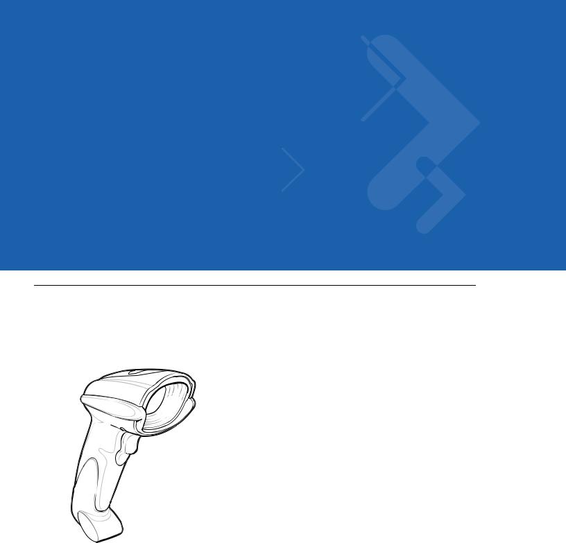
The Symbol DS6707 digital imager scanner combines superior 1D and 2D omnidirectional bar code scanning and sub-second image capture and transfer to provide the best value in a digital imager scanner. Whether in hand-held mode or presentation (hands-free) mode in a stand, the digital imager scanner ensures comfort and ease of use for extended periods of time.
Figure 1-1 Symbol DS6707 Digital Imager Scanner
Getting Started |
1 - 2 |
|
|
Supported Interfaces
The Symbol DS6707digital imager scanner supports:
•Simple Serial Interface (SSI) connection to a host. When using SSI, program the digital imager scanner via bar code menu or SSI host commands.
•Standard RS-232 connection to a host. Scan bar code menus to set up communication between the digital imager scanner and the host.
•USB connection to a host. The digital imager scanner autodetects a USB host and defaults to the HID keyboard interface type. Select other USB interface types by scanning programming bar code menus.This interface supports the following international keyboards (for Windows® environment): North America, German, French, French Canadian, Spanish, Italian, Swedish, UK English, Portuguese-Brazilian, and Japanese.
•Configuration via 123Scan.
Unpacking
Remove the digital imager scanner from its packing and inspect it for damage. If the scanner was damaged in transit, contact Motorola Enterprise Mobility Support. See page xvii for contact information. KEEP THE PACKING. It is the approved shipping container; use this to return the equipment for servicing.
1 - 3 Symbol DS6707 Digital Imager Scanner Product Reference Guide
Setting Up the Digital Imager Scanner
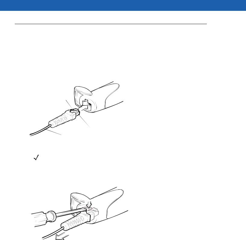
Installing the Interface Cable
1.Plug the interface cable modular connector into the cable interface port on the bottom of the scanner handle. See Figure 1-2.
2.Gently tug the cable to ensure the connector is properly secured.
3.Connect the other end of the interface cable to the host (see the specific host chapter for information on host connections).
Clip
 Cable interface port
|
Interface cable modular |
To host |
connector |
|
Figure 1-2 Installing the Cable
NOTE Different hosts require different cables. The connectors illustrated in each host chapter are examples only. Connectors vary from those illustrated, but the steps to connect the digital imager scanner are the same.
Removing the Interface Cable
1.Using the tip of a screwdriver, depress the cable’s modular connector clip.
Figure 1-3 Removing the Cable
2.Carefully slide out the cable.
3.Follow the steps for Installing the Interface Cable to connect a new cable.

Getting Started |
1 - 4 |
|
|
Connecting Power (if required)
If the host does not provide power to the digital imager scanner, connect an external power supply:
1.Connect the interface cable to the bottom of the digital imager scanner, as described in Installing the Interface Cable on page 1-3.
2.Connect the other end of the interface cable to the host (refer to the host manual to locate the correct port).
3.Plug the power supply into the power jack on the interface cable. Plug the other end of the power supply into an AC outlet.
Configuring the Digital Imager Scanner
To configure the digital imager scanner, use the bar codes in this manual, or the 123Scan configuration program.
See Chapter 4, User Preferences & Miscellaneous Digital Imager Scanner Options and Chapter 5, Imaging Preferences for information about programming the digital imager scanner using bar code menus. Also see each host-specific chapter to set up connection to a specific host type.
See Chapter 9, 123Scan to configure the digital imager scanner using this configuration program. The program includes a help file.
Mounting the Digital Imager Scanner
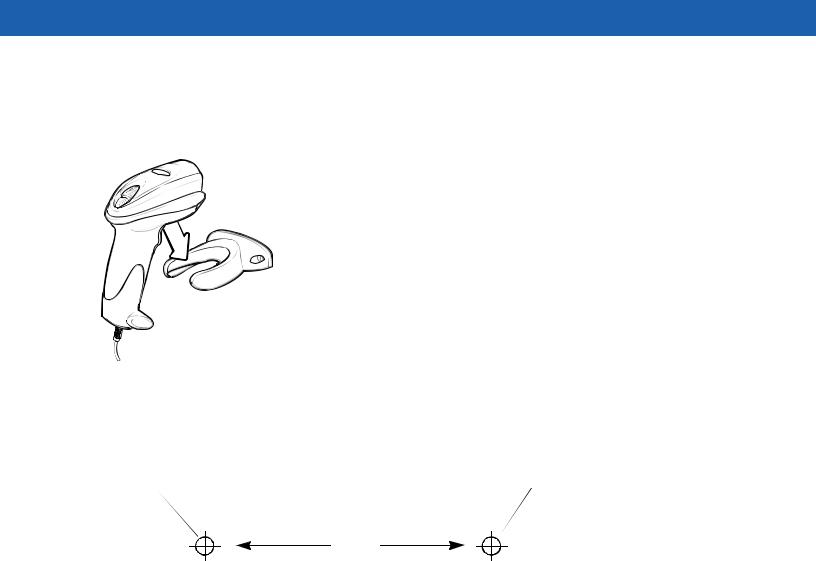
Desk Mount
Use the optional desk mount for convenient and protective placement of the digital imager scanner on a flat surface. Simply place the mount on the surface. The rubber feet hold the mount securely in place when inserting and removing the digital imager scanner.
Figure 1-4 Inserting the Digital Imager Scanner in the Desk Mount
Alternatively, secure the desk mount to a desk surface by inserting two screws* appropriate for the mounting surface through the screw holes of the desk mount, and into the surface. Screw the desk mount onto the surface with or without the rubber feet.
*The recommended screws are two #6 screws (5/8” long).
1 - 5 Symbol DS6707 Digital Imager Scanner Product Reference Guide
Wall Mount
To use the optional wall mount to mount the digital imager scanner on a wall, place the mount in the desired location on the wall and secure by inserting two screws* appropriate for the mounting surface through the screw holes on the mount, and into the surface. Insert the digital imager scanner into the mount as shown.
Figure 1-5 Securing the Wall Mount
*The recommended screws are two #6 screws (1” long) and two #6 washers.
For convenience, print this page and use the template below for mounting hole locations.
Insert mounting screw |
Insert mounting screw |
2.98”
Figure 1-6 Wall Mounting Template
Chapter 2 Scanning
Introduction
This chapter provides beeper and LED definitions, techniques involved in scanning bar codes, general instructions and tips about scanning, and decode zone diagrams.
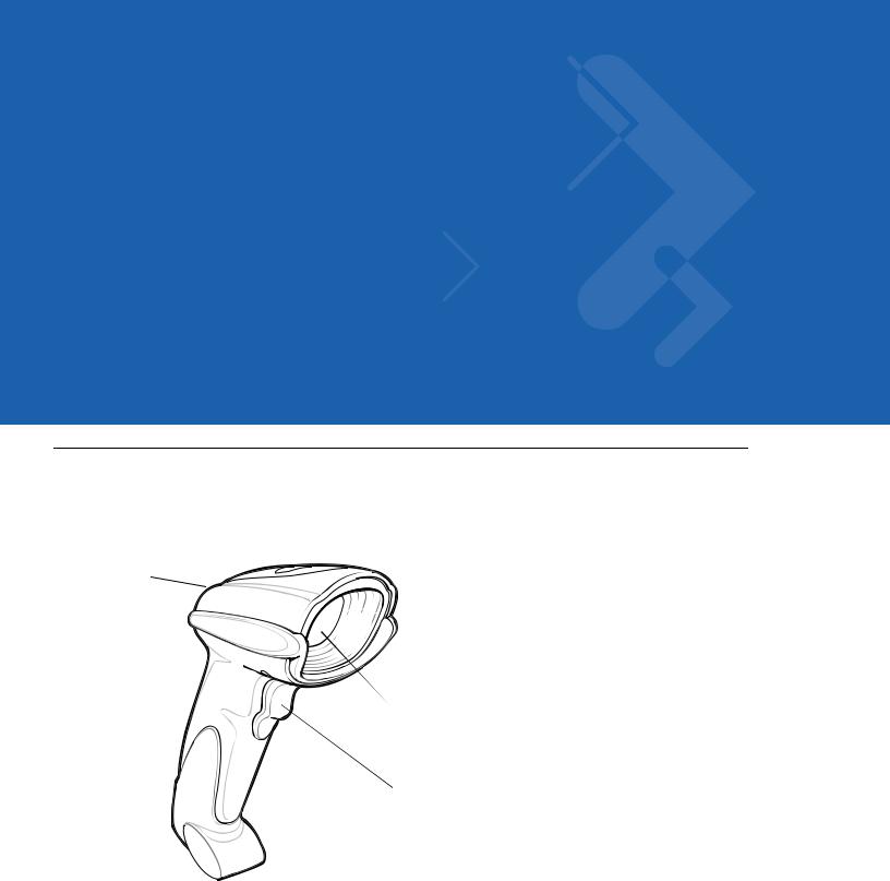
LED
Beeper 
Scan
Window
 Trigger
Figure 2-1 Parts

2 - 2 Symbol DS6707 Digital Imager Scanner Product Reference Guide
Beeper Definitions
The digital imager scanner issues different beep sequences and patterns to indicate status. Table 2-1 defines beep sequences that occur during both normal scanning and while programming the digital imager scanner.
Table 2-1 Beeper Definitions
Beeper Sequence |
Indication |
|
|
Standard Use |
|
|
|
Low/medium/high beeps |
Power up. |
|
|
Short high beep |
A bar code symbol was decoded (if decode beeper is enabled). |
|
|
4 long low beeps |
A transmission error was detected in a scanned symbol. The data is ignored. This |
|
occurs if the digital imager scanner is not properly configured. Check option |
|
setting. |
|
|
5 low beeps |
Conversion or format error. |
|
|
Low/high/low beeps |
ADF transmit error. See Chapter 11, Advanced Data Formatting. |
|
|
High/high/high/low beeps |
RS-232 receive error. |
|
|
Parameter Menu Scanning |
|
|
|
Short high beep |
Correct entry scanned or correct menu sequence performed. |
|
|
Low/high beeps |
Input error; incorrect bar code, programming sequence, or Cancel scanned; |
|
remain in ADF program mode. |
|
|
High/low beeps |
Keyboard parameter selected. Enter value using numeric bar codes. |
|
|
High/low/high/low beeps |
Successful program exit with change in parameter setting. |
|
|
Low/high/low/high beeps |
Out of host parameter storage space. Scan Set Default Parameter on page 4-4. |
|
|
Code 39 Buffering |
|
|
|
High/low beeps |
New Code 39 data was entered into the buffer. |
|
|
3 long high beeps |
Code 39 buffer is full. |
|
|
Low/high/low beeps |
The Code 39 buffer was erased or there was an attempt to clear or transmit an |
|
empty buffer. |
|
|
Low/high beeps |
A successful transmission of buffered data. |
|
|
Macro PDF |
|
|
|
2 long low beeps |
File ID error. A bar code not in the current MPDF sequence was scanned. |
|
|
|
|
3 long low beeps |
Out of memory. There is not enough buffer space to store the current MPDF |
|
symbol. |
|
|
4 long low beeps |
Bad symbology. Scanned a 1D or 2D bar code in a MPDF sequence, a duplicate |
|
MPDF label, a label in an incorrect order, or trying to transmit an empty or illegal |
|
MPDF field. |
|
|
5 long low beeps |
Flushing MPDF buffer. |
|
|

Scanning 2 - 3
Table 2-1 Beeper Definitions (Continued)
Beeper Sequence |
Indication |
|
|
Fast warble beep |
Aborting MPDF sequence. |
|
|
Low/high beeps |
Flushing an already empty MPDF buffer. |
|
|
ADF Programming: Normal Data Entry. Duration of tones are short.
High/low beeps |
Enter another digit. Add leading zeros to the front if necessary. |
|
|
Low/low beeps |
Enter another alphabetic character or scan the End of Message bar code. |
|
|
High/high beeps |
Enter another criterion or action, or scan the Save Rule bar code. |
|
|
High/low/high/low beeps |
Rule saved. Rule entry mode exited. |
|
|
High/low/low beeps |
All criteria or actions cleared for current rule, continue entering rule. |
|
|
Low beep |
Delete last saved rule. The current rule is left intact. |
|
|
Low/high/high beeps |
All rules are deleted. |
|
|
ADF Programming: Error Indications. Duration of tones are very long.
Low/high/low/high beeps |
Out of rule memory. Erase some existing rules, then try to save rule again. |
|
(It is not necessary to re-enter the current rule.) |
|
|
Low/high/low beeps |
Cancel rule entry. Rule entry mode exited because of an error or the user asked to |
|
exit rule entry. |
|
|
Low/high beeps |
Entry error, wrong bar code scanned. Re-enter criterion or action. All previously |
|
entered criteria and actions are retained. Criteria or action list is too long for a rule. |
|
|
Host Specific |
|
|
|
USB only |
|
|
|
4 short high beeps |
The digital imager scanner has not completed initialization. Wait several seconds |
|
and scan again. |
|
|
Low/medium/high beeps |
Communication with the bus must be established before the digital imager scanner |
upon scanning a USB |
can operate at the highest power level. |
device type |
|
|
|
Low/medium/high beeps |
The USB bus can put the digital imager scanner in a state where power to the |
occur more than once. |
digital imager scanner is cycled on and off more than once. This is normal and |
|
usually happens when the PC cold boots. |
|
|
RS-232 only |
|
|
|
1 short high beep |
A <BEL> character is received and Beep on <BEL> is enabled. |
|
|
2 - 4 Symbol DS6707 Digital Imager Scanner Product Reference Guide
LED Definitions
In addition to beep sequences, the digital imager scanner uses a two-color LED to indicate status. Table 2-2 defines LED colors that display during scanning.
Table 2-2 Standard LED Definitions
LED |
Indication |
|
|
Off |
No power is applied to the digital imager scanner, or the digital imager scanner is on and |
|
ready to scan. |
|
|
Green |
A bar code was successfully decoded. |
|
|
Red |
A data transmission error or digital imager scanner malfunction occurred. |
|
|
Scanning in Hand-Held Mode
Install and program the digital imager scanner (see Setting Up the Digital Imager Scanner on page 1-3). For assistance, contact the local supplier or Motorola Enterprise Mobility Support.
Scanning with the Digital Imager Scanner
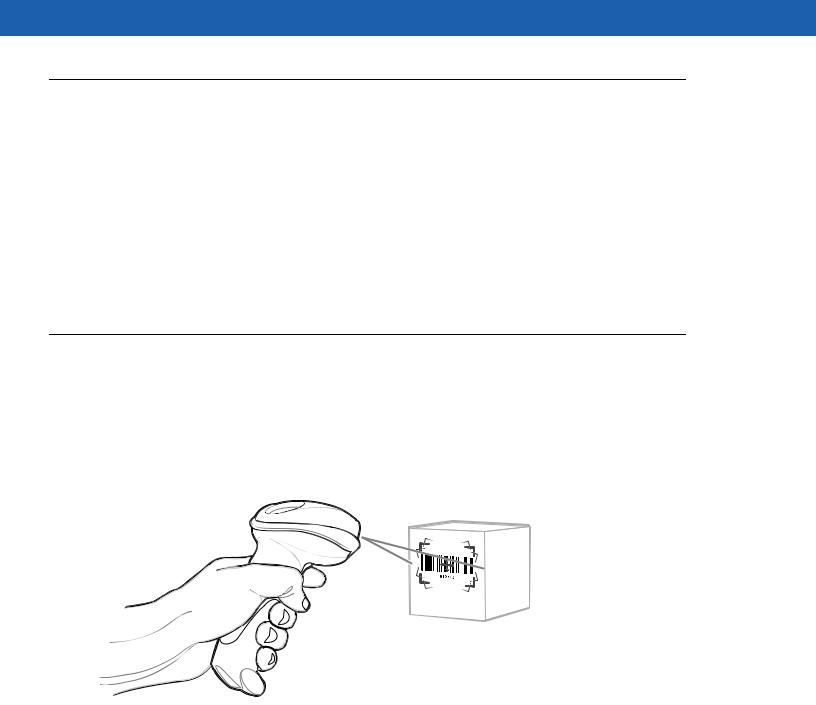
1.Ensure all connections are secure (see the appropriate host chapter.)
2.Aim the digital imager scanner at the bar code.
Figure 2-2 Scanning in Hand-Held Mode
Scanning 2 - 5
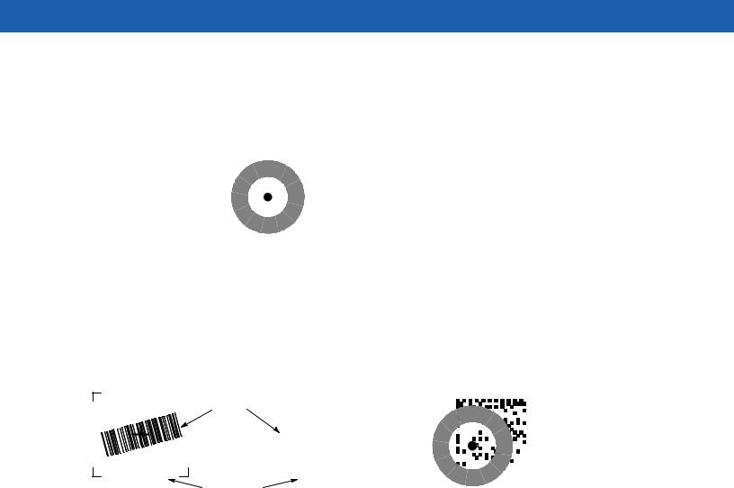
3.When the digital imager scanner senses movement, in its default Auto Aim trigger mode, it projects a red laser aiming pattern (Figure 2-3) which allows positioning the bar code or object within the field of view. (To turn off the default Auto Aim trigger mode, see Trigger Mode on page 4-8.) If necessary, the digital imager scanner turns on its red LEDs to illuminate the target bar code.
The DS6707-DP version uses a donut-shaped pattern with a center aiming dot.
|
|
|
|
|
|
|
|
|
|
|
|
|
|
|
|
|
|
|
|
|
|
|
|
|
|
|
|
|
|
|
|
|
|
|
|
|
|
|
|
|
|
|
|
|
|
|
|
|
|
|
|
|
|
Standard Pattern |
DS6707-DP Pattern |
|||||||
Figure 2-3 Laser Aiming Pattern
4.Center the symbol in any orientation within the aiming pattern. Be sure the entire symbol is within the rectangular area formed by the brackets in the pattern.
When scanning with the DS6707-DP, ensure part of the bar code is visible on the inside of the donut-shaped pattern.
Linear1D barbarcode |
|
2D bar code |
Data Matrix bar code |
|||
|
PDF417 symbol |
|
||||
|
|
|
|
|
|
|
|
|
|
|
|
|
|
Symbol
|
|
|
|
|
|
|
|
|
|
|
|
|
|
|
|
|
|
|
|
|
|
|
|
|
|
|
|
|
|
|
|
|
|
|
|
|
|
|
|
|
|
|
|
|
|
|
|
|
|
DS6707-DP Pattern |
||||||||||||
Aiming Pattern |
|
|||||||||||||||||||
Figure 2-4 Placing Symbol in Aiming Pattern
5.Hold the trigger until the digital imager scanner beeps, indicating the bar code is successfully decoded. For more information on beeper and LED definitions, see Table 2-1 and Table 2-2.
This process usually occurs instantaneously. Steps 2 - 4 are repeated on poor quality or difficult bar codes, until the bar code is decoded, the trigger is released, or the Decode Session Timeout is reached.

2 - 6 Symbol DS6707 Digital Imager Scanner Product Reference Guide
Aiming
Hold the digital imager scanner between two and nine inches (depending on symbol density; see Decode Zones on page 2-8) from the symbol, centering the aiming pattern on the symbol. Ensure the cross hair falls on the symbol. For the DS6707-DP, ensure part of the symbol is visible within the donut-shaped pattern.
The aiming pattern is smaller when the digital imager scanner is closer to the symbol and larger when it is farther from the symbol. Scan symbols with smaller bars or elements (mil size) closer to the digital imager scanner, and those with larger bars or elements (mil size) farther from the digital imager scanner.
The digital imager scanner can also read a bar code presented within the aiming pattern but not centered. The top examples in Figure 2-5 and Figure 2-6 show acceptable aiming options, while the bottom examples can not decode.
NOTE For best performance, ensure the pattern’s cross hair, or in the case of the DS6707-DP the aiming dot, falls on the symbol.
0 1 2 3 4 5 |
|
|
0 1 2 3 4 5 |
|
|||
|
|
|
|
|
|
|
|
0 1 2 3 4 5 |
0 1 2 3 4 5 |
Figure 2-5 Acceptable and Incorrect Aiming - Standard Pattern
Figure 2-6 Acceptable and Incorrect Aiming - DS6707-DP Pattern
 Loading...