


 Loading...
Motorola, the Stylized M Logo, and all other trademarks indicated as such herein are Trademarks of Motorola, Inc. Reg. U.S. Pat. & Tm. Off. © 2007 Motorola, Inc. All rights reserved.

CONTENTS
Contents. . . . . . . . . . . . . . . . . . . . . . . . . . . . 1
Safety . . . . . . . . . . . . . . . . . . . . . . . . . . . . . . 5
Batteries and Chargers Safety
Information. . . . . . . . . . . . . . . . . . . . . . . . . . 6
Operational Safety Guidelines. . . . . . . . . . . . .7
Introduction . . . . . . . . . . . . . . . . . . . . . . . . . 8
Package Contents. . . . . . . . . . . . . . . . . . . . . .8
FCC Licensing Information . . . . . . . . . . . 10
Interference Information . . . . . . . . . . . . . . . .10
Radio Overview . . . . . . . . . . . . . . . . . . . . . 12
Parts of the Radio . . . . . . . . . . . . . . . . . . . . .12
On/Off/Volume Knob. . . . . . . . . . . . . . . .13
Accessory Connector . . . . . . . . . . . . . . .13
Model Label . . . . . . . . . . . . . . . . . . . . . .13
Microphone . . . . . . . . . . . . . . . . . . . . . . .13
Antenna. . . . . . . . . . . . . . . . . . . . . . . . . .13
LED Indicator . . . . . . . . . . . . . . . . . . . . .13
Front Buttons |
|
13 |
|
|
. . . |
|
|
||
Side Buttons . . . . . . . . . . . . . . . . . |
. . . |
. 14 |
|
|
The Lithium-Ion (Li-Ion) Battery . . . |
. . . |
. 14 |
|
CONTENTS |
Battery Features. . . . . . . . . . . . . . . . . . |
. . . |
. 16 |
|
|
. . . . . . . . .About the Li-Ion Battery |
. . . |
. 16 |
|
|
Battery Recycling and Disposal . . . |
. . . |
. 17 |
|
|
Installing the Lithium-Ion (Li-Ion) |
|
|
|
|
Battery . . . . . . . . . . . . . . . . . . . . . . |
. . . |
. 18 |
|
|
Removing the Lithium-Ion (Li-Ion) |
|
|
|
|
Battery . . . . . . . . . . . . . . . . . . . . . . |
. . . |
. 18 |
|
|
Alkaline Battery Pack (Optional |
|
|
|
|
Accessory) . . . . . . . . . . . . . . . . . . . |
. . . |
. 19 |
|
|
Installing Alkaline Batteries . . . . . . |
. . . |
. 19 |
|
|
Removing Alkaline Batteries . . . . . |
. . . |
. 19 |
|
|
Attaching and Removing Antenna . |
. . . |
. 20 |
|
|
Attaching the Antenna . . . . . . . . . . |
. . . |
. 20 |
|
|
Removing the Antenna . . . . . . . . . |
. . . |
. 20 |
|
|
Installing Spring Action Belt Clip . . |
. . . |
. 21 |
|
|
Power Supply, Adaptor and Drop-in |
|
|
|
|
Tray Charger . . . . . . . . . . . . . . . . . |
. . . |
. 21 |
|
|
Battery Life Information . . . . . . . . . |
. . . |
. 22 |
|
|
Alkaline Battery Life . . . . . . . . . . . . |
. . . |
. 23 |
|
|
Charging the Battery . . . . . . . . . . . |
. . . |
. 25 |
|
|
|
1 |
|
|
|
|
English |
|
||
|
|
|
||
|
|
|
|
|
|
|
Getting Started |
32 |
|
|
|
|||
|
|
Turning radio ON/OFF. . . . . . . . . . . . . . . . . . |
32 |
|
CONTENTS |
|
Adjusting volume . . . . . . . . . . . . . . . . . . . . . . |
32 |
|
|
Receiving a Call . . . . . . . . . . . . . . . . . . . . . . |
33 |
||
|
|
Reading the Display . . . . . . . . . . . . . . . . . . . |
32 |
|
|
|
Selecting a Channel . . . . . . . . . . . . . . . . . . . |
33 |
|
|
|
Talking and Monitoring . . . . . . . . . . . . . . . . . |
33 |
|
|
|
Signal Strength Indicator and Channel |
|
|
|
|
Busy Indicators . . . . . . . . . . . . . . . . . . . . |
34 |
|
|
|
Talk Range . . . . . . . . . . . . . . . . . . . . . . . . . . |
34 |
|
|
|
. . . . . . . . . . . . . . . . . .Radio LED Indicators |
36 |
|
|
|
Hands-Free Use/VOX . . . . . . . . . . . . . . . . . . |
37 |
|
|
|
With Compatible VOX Accessories. . . . . |
37 |
|
|
|
Hands Free without Accessories |
|
|
|
|
(iVOX) . . . . . . . . . . . . . . . . . . . . . . . . . . . |
38 |
|
|
|
Battery Save . . . . . . . . . . . . . . . . . . . . . . |
38 |
|
|
|
Reset to Factory Defaults . . . . . . . . . . . . |
38 |
|
|
|
End of Transmission Tone (Roger |
|
|
|
|
Beep Tone) . . . . . . . . . . . . . . . . . . . . . . . |
39 |
|
|
|
Keypad Beeps. . . . . . . . . . . . . . . . . . . . . |
39 |
|
|
|
Keypad Lock/Unlock . . . . . . . . . . . . . . . . |
39 |
|
|
|
MENU Options . . . . . . . . . . . . . . . . . . . . |
39 |
|
|
|
Setting VOX / iVOX sensitivity . . . . . . . . |
40 |
|
|
|
|
2 |
|
English |
|
|
||
|
|
|
||
|
|
|
|
|
Programming Features . . . . . . . . . . . . . . . 42
Entering Programming Mode . . . . . . . . . . . . 42 Programming RX (Reception) Frequencies . 43 Programming RX (Reception) Codes (CTCSS/DPL). . . . . . . . . . . . . . . . . . . . . . . . 44 Programming RX (Reception) Bandwidth . . 44 Programming Scramble L. . . . . . . . . . . . . . 45 Programming Maximum Number of
Channels . . . . . . . . . . . . . . . . . . . . . . . . . . . 46 Programming Call Tones . . . . . . . . . . . . . . . 46 Programming Microphone Gain Level . . . . . 47 Programming Microphone Accessory
Gain Level . . . . . . . . . . . . . . . . . . . . . . . . . . 48 Other Programming Features . . . . . . . . . . . 48 Scan. . . . . . . . . . . . . . . . . . . . . . . . . . . . 48 Programming Buttons . . . . . . . . . . . . . . . . . 50 Editing Channel Alias Name . . . . . . . . . . . . 50 Nuisance Channel Delete . . . . . . . . . . . . . . 52 CPS (Computer Programming Software). . . 53 Bandwidth Select . . . . . . . . . . . . . . . . . . 54 Time-Out Timer . . . . . . . . . . . . . . . . . . . 54 Power Select . . . . . . . . . . . . . . . . . . . . . 54 Battery Type Setting . . . . . . . . . . . . . . . 54

Call Tones. . . . . . . . . . . . . . . . . . . . . . . .55 Scramble. . . . . . . . . . . . . . . . . . . . . . . . .55 Reverse Burst . . . . . . . . . . . . . . . . . . . . .55 Cloning Radios . . . . . . . . . . . . . . . . . . . . . . .56
Cloning with a Multi-Unit Charger
(MUC) . . . . . . . . . . . . . . . . . . . . . . . . . . .56 Cloning Radios using the Radio to
Radio (R2R) Cloning Cable
(optional accessory) . . . . . . . . . . . . . . . .58 Cloning Radios using the CPS
(Computer Programming Software) . . . .60 Repeater Capabilities . . . . . . . . . . . . . . .60
Troubleshooting . . . . . . . . . . . . . . . . . . . . 63
Use and Care . . . . . . . . . . . . . . . . . . . . . . 67
Frequency and Code Charts . . . . . . . . . . 68
RDX VHF Frequencies Chart . . . . . . . . . . . .68
RDV2080d - VHF Default Frequencies
Chart . . . . . . . . . . . . . . . . . . . . . . . . . . . . . . .70
Making XTN Compatible with RDX
Radios - Quick Instructions . . . . . . . . . . . . . 71 RDX UHF Frequencies Chart. . . . . . . . . . . . 72 RDU2080d - UHF Default Frequencies
Chart . . . . . . . . . . . . . . . . . . . . . . . . . . . . . . 76 RDU4160d - UHF Default Frequencies
Chart . . . . . . . . . . . . . . . . . . . . . . . . . . . . . . 77 CTCSS and PL/DPL Codes . . . . . . . . . . . . . 79 Programming Customized Frequencies
on 4W/5W RDX models . . . . . . . . . . . . . . . . 82
Motorola Limited Warranty for the
United States and Canada. . . . . . . . . . . . . 83
Accessories . . . . . . . . . . . . . . . . . . . . . . . . 87
Antennas . . . . . . . . . . . . . . . . . . . . . . . . . . . 87
Audio Accessories . . . . . . . . . . . . . . . . . . . . 87
Battery . . . . . . . . . . . . . . . . . . . . . . . . . . . . . 87
Carry Accessories . . . . . . . . . . . . . . . . . . . . 88
Power Supplies AC Pin Adaptors. . . . . . . . . 88
CONTENTS
3 English

CONTENTS
Software Applications . . . . . . . . . . . . . . . . . . |
88 |
RDX Series™ Features Summary . . . . . |
. 90 |
|
Cables . . . . . . . . . . . . . . . . . . . . . . . . . . . . . . |
88 |
Programmable Buttons Chart |
99 |
|
Chargers |
88 |
|||
Icons Chart |
100 |
|||
Power Supplies . . . . . . . . . . . . . . . . . . . . . . . |
89 |
English 4

SAFETY
PRODUCT SAFETY AND RF EXPOSURE COMPLIANCE
!
C a u t i o n
Before using this product, read the operating instructions and RF energy awareness information contained in the Product Safety and RF Exposure booklet enclosed with your radio.
ATTENTION!
This radio is restricted to occupational use only to satisfy FCC RF energy exposure requirements.
For a list of Motorola-approved antennas, batteries, and other accessories, visit the following website which lists approved accessories:
http://www.motorola.com/RDX
SAFETY
5 English

BATTERIES AND CHARGERS SAFETY INFORMATION
BATTERIES AND
CHARGERS SAFETY
INFORMATION
This document contains important safety and operating instructions. Read these instructions carefully and save them for future reference.
Before using the battery charger, read all the instructions and cautionary markings on
•the charger,
•the battery, and
•the radio using the battery
1.To reduce risk of injury, charge only the rechargeable Motorola-authorized batteries. Other batteries may explode, causing personal injury and damage.
2.Use of accessories not recommended by Motorola may result in risk of fire, electric shock, or injury.
3.To reduce risk of damage to the electric plug and cord, pull by the plug rather than the cord when disconnecting the charger.
4.An extension cord should not be used unless absolutely necessary. Use of an improper extension cord could result in risk of fire and electric shock. If an extension cord must be used, make sure that the cord size is 18AWG for lengths up to 6.5 feet (2.0 m), and 16AWG for lengths up to 9.8 feet (3.0 m).
5.To reduce risk of fire, electric shock, or injury, do not operate the charger if it has been broken or damaged in any way. Take it to a qualified Motorola service representative.
6.Do not disassemble the charger; it is not repairable and replacement parts are not available. Disassembly of the charger may result in risk of electrical shock or fire.
7.To reduce risk of electric shock, unplug the charger from the AC outlet before attempting any maintenance or cleaning
English 6

OPERATIONAL SAFETY
GUIDELINES
•Turn the radio OFF when charging battery.
•The charger is not suitable for outdoor use. Use only in dry locations/conditions.
•Connect charger only to an appropriately fused and wired supply of the correct voltage (as specified on the product).
•Disconnect charger from line voltage by removing main plug.
•The outlet to which this equipment is connected should be nearby and easily accessible.
•Maximum ambient temperature around the power supply equipment must not exceed 40°C (104°F).
•Power output from the power supply unit must not exceed the ratings stated on the product label located at the bottom of the charger.
CHARGERS AND BATTERIES
INFORMATION SAFETY
7 English

INTRODUCTION
INTRODUCTION
Thank you for purchasing the Motorola® RDX Series™ Radio. This radio is a product of Motorola's 75 plus years of experience as a world leader in the designing and manufacturing of communications equipment. The RDX Series™ radios provide cost-effective communications for businesses such as retail stores, restaurants, schools, construction sites, manufacturing, property and hotel management and more. Motorola Business two-way radios are the perfect communications solution for all of today's fast-paced industries.
Note: Read this user guide carefully to ensure you know how to properly operate the radio before use
Business Radios,
RPSD 1C15, Motorola
8000 West Sunrise Boulevard
Plantation, Florida 33322
PACKAGE CONTENTS
•Radio
•Antenna (only for RDU4160d)
•Spring Action Belt-Clip
•Lithium-Ion Battery
•Power Supply
•User Guide
•Warranty Card
•Drop-in Tray Charger
•Product Safety & RF Exposure Booklet
English 8
For a copy of a large-print version of this user |
For product information visit us at: |
guide or for product-related questions, contact: |
www.motorola.com/radios/business |
1-800-448-6686 in the USA |
or visit our microsite at: |
1-800-461-4575 in Canada |
www.motorola.com/RDX |
1-866-522-5210 on your TTY (Text |
|
Telephone) |
|
INTRODUCTION
9 English

FCC LICENSING INFORMATION
FCC LICENSING
INFORMATION
INTERFERENCE INFORMATION
This device complies with Part 15 of the FCC Rules. Operation is subject to the condition that this device does not cause harmful interference.
RDX Series™ Business two-way radios operate on radio frequencies that are regulated by the Federal Communications Commission
(FCC). To transmit on these frequencies, you are required to have a license issued by the FCC. Application is made available on FCC Form 601 and Schedules D, H, and Remittance Form 159.
To obtain these FCC forms, request document 000601 which includes all forms and instructions. If you wish to have the document faxed, mailed or have questions, use the following contact information.
Faxed contact the |
Mailed call the FCC forms hotline at: |
Questions regarding FCC |
|
Fax-On- Demand |
|||
license contact the FCC at: |
|||
system at: |
|
||
|
|
||
|
|
|
|
1-202-418-0177 |
1-800-418-FORM |
1-888-CALL-FCC |
|
|
1-800-418-3676 |
1-888-225-5322 |
|
|
|
Or: http://www.fcc.gov |
|
|
|
|
English 10

Before filling out your application, you must decide which frequency(ies) you can operate on. See “Frequencies and Code Charts”. For questions on determining the radio frequency, call Motorola Product Services at:
1-800-448-6686
Changes or modifications not expressly approved by Motorola may void the user’s authority granted by the FCC to operate this radio and should not be made. To comply with FCC requirements, transmitter adjustments should be made only by or under the supervision of a person certified as technically qualified to perform transmitter maintenance and repairs in the private land mobile and fixed services as certified by an organization representative of the user of those services.
Replacement of any transmitter component (crystal, semiconductor, etc.) not authorized by the FCC equipment authorization for this radio could violate FCC rules.
Use of this radio outside the country where it was intended to be distributed is subject to government regulations and may be prohibited
LICENSING FCC
INFORMATION
11 English
RADIO OVERVIEW
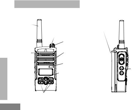
PARTS OF THE RADIO
Antenna
On/Off/ |
Lithium-Ion |
Volume |
Battery |
Knob |
|
|
LED Indicator |
RADIO OVERVIEW
Microphone
Use ‘Menu’ button to lock keypad 
Front Buttons
Accessory
Connector
Model Label
Use  and
and  to scroll up/ down through channels and menu setting
PTT (Push-to-Tal
 Button
SB1 - Monitor
Button
SB2 - Nuisance
Channel Delete
English 12

On/Off/Volume Knob
Used to turn the radio ON or OFF and to adjust the radio’s volume.
Accessory Connector
Used to connect compatible audio accessories.
Model Label
Indicates the model of the radio
Microphone
Speaks clearly into the microphone when sending a message.
Antenna
For Models RDU2080d and RDV2080d, the antennas are non-removable antenna. For RDU4160d, the antenna is removable.
LED Indicator
Used to give battery status, power-up status, radio call information and scan status.
Front Buttons
•M E N U Button
This button give you access to set up features like VOX/ iVOX levels, battery type, etc. It also allows you to move through all the features while in Programming Mode.
•
 Toggle up / down buttons
Allows you to change channels and to scroll up/ down menu options or set up programming values. These buttons are not programmable buttons.
OVERVIEW RADIO
13 English

RADIO OVERVIEW
• |
A Programmable Button |
Default set to generate the current programmed call tone.
•B Programmable Button
Default set to preset Channel 1
•C Programmable Button
Default set to preset Channel 2
Note: A short press of either preset button (B or C) tunes the radio to the preset channel and the radio will play a good chirp. You can assign different functions to these buttons via the CPS. For example: Backlight Time Out, Reverse Burst, Power Select, Scan/ Nuisance Channel Delete, Monitor and Call Tones. To learn more about how to program these buttons refer to “Entering Programming Mode” on page 42 and “CPS (Computer Programming Software)” on page 53
Side Buttons
Push-to-Talk (PTT) Button
Press and hold down this button to talk, release it to listen.
Side Button 1 (SB1)
The Side Button 1 is a general button that can be configured by the CPS. The default setting of the SB1 button is ‘Monitor’.
Side Button 2 (SB2)
The Side Button 2 is a general button that can be configured by the CPS. The SB2 button default setting is ‘Scan/Nuisance Channel Delete’.
The Lithium-Ion (Li-Ion) Battery
RDX Series™ provides different types of batteries. For more information, see “Battery Features” on page 16.
English 14

This User Guide covers multiple RDX Series™ models, and may detail some features your radio does not have. The radio’s model is
shown on the front of the radio, underneath the speaker, and tells you the following information:
Model |
Frequency |
Transmit |
Number of |
Antenna |
|
Band |
Power (Watts) |
Channels |
|||
|
|
||||
|
|
|
|
|
|
RDV2080d |
VHF |
2 |
8 |
Non-removable |
|
|
|
|
|
|
|
RDU2080d |
UHF |
2 |
8 |
Non-removable |
|
|
|
|
|
|
|
RDU4160d |
UHF |
4 |
16 |
Removable |
|
|
|
|
|
|
OVERVIEW RADIO
15 English

RADIO OVERVIEW
English
BATTERY FEATURES
RDX Series™ radios provide Lithium-Ion batteries that come in different capacities that will define the battery life. It also offers the option to use Alkaline batteries.
About the Li-Ion Battery
The RDX Series™ radio comes equipped with a rechargeable Li-Ion battery. This battery should be charged before initial use to ensure optimum capacity and performance.
Battery life is determined by several factors. Among the more critical are the regular overcharge of batteries and the average depth of discharge with each cycle. Typically, the greater the overcharge and the deeper the average discharge, the fewer cycles a battery will last. For example, a battery which is overcharged and discharged 100% several times a day, lasts fewer cycles than a battery that receives less of an overcharge and is discharged to 50% per day. Further, a battery
16
which receives minimal overcharging and averages only 25% discharge, lasts even longer.
Motorola batteries are designed specifically to be used with a Motorola charger and vice versa. Charging in non-Motorola equipment may lead to battery damage and void the battery warranty. The battery should be at about 77°F (25°C) (room temperature), whenever possible. Charging a cold battery (below 50° F [10°C]) may result in leakage of electrolyte and ultimately in failure of the battery. Charging a hot battery (above 95°F [35°C]) results in reduced discharge capacity, affecting the performance of the radio. Motorola rapid-rate battery chargers contain a temperature-sensing circuit to ensure that batteries are charged within the temperature limits stated above.

Battery Recycling and Disposal
Li-Ion rechargeable batteries can be recycled. However, recycling facilities may not be available in all areas. Under various U.S. state laws and the laws of several other countries, batteries must be recycled and cannot be disposed of in landfills or incinerators. Contact your local waste management agency for specific requirements and information in your area. Motorola fully endorses and encourages the recycling of Li-Ion batteries. In the U.S. and Canada, Motorola participates in the nationwide Rechargeable Battery Recycling Corporation (RBRC) program for Li-Ion battery collection and recycling.
Many retailers and dealers participate in this program. For the location of the drop-off facility closest to you, access RBRC's Internet web site at:
www.rbrc.com or call:
1-800-8-BATTERY
This internet site and telephone number also provides other useful information concerning recycling options for consumers, businesses and governmental agencies.
OVERVIEW RADIO
17 English

RADIO OVERVIEW
Installing the Lithium-Ion (Li-Ion) Battery
Battery
Latch
slots
1.Turn OFF the radio.
2.With the Motorola logo side up on the battery pack, fit the tabs at the bottom of the battery into the slots at the bottom of the radio’s body.
3.Press the top part of the battery towards the radio until a click is heard.
Note: To learn about the Li-Ion Battery Life features, refer to “About the Li-Ion Battery” on page 16
Removing the Lithium-Ion (Li-Ion) Battery
Battery
 Latch
Latch
1.Turn OFF the radio.
2.Push down the battery latch and hold it depressed while removing the battery.
3.Pull the battery away from the radio.
English 18
Alkaline Battery Pack (Optional Accessory) |
|
Installing Alkaline Batteries |
Removing Alkaline Batteries |
Alkaline
Battery
Door
1.Turn OFF the radio, if it is turned ON.
2.Remove Li-Ion battery.
3.Assemble alkaline battery pack in the same steps as installing the Li-Ion battery pack.
4.Remove battery door from alkaline battery pack.
5.Slide the 5 AA alkaline batteries into the frame, matching the markings inside the compartment
Alkaline
Battery
Door
1.Turn OFF the radio, if it is turned ON.
2.Slide the battery latches, on both sides of the battery, downwards.
3.Pull the top of the battery away from the radio’s body, and lift the battery from the radio’s body.
OVERVIEW RADIO
19 English
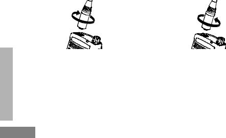
Attaching and Removing Antenna
These instructions apply ONLY for RDU4160d radio. Do not attempt to remove the antenna if your radio is not one of these models.
Attaching the Antenna |
Removing the Antenna |
RADIO OVERVIEW
1. |
Align the threaded end of the antenna with the |
1. |
Turn the antenna counterclockwise until you |
|
radio’s antenna connector. |
|
can remove it. |
2.Turn the antenna clockwise to fasten it.
English 20
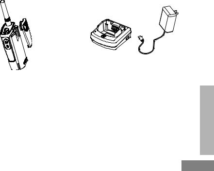
Installing Spring Action Belt Clip |
Power Supply, Adaptor and Drop-in Tray |
|
Charger |
Belt Clip
 Tab
Tab
 Spring
Action Belt
Clip
1.Slide the spring action belt clip rails into the belt clip grooves on the back of the battery pack and slide it down until the belt clip tab snaps into place.
2.To remove, pull back the metal release tab on the belt clip tab and push the spring action belt clip upward to remove.
Power Supply
Drop-in Tray Charger
The radio is equipped with one Drop-in Tray Charger and one Power Supply with Adaptor. For details, see “Chargers” on page 88.
OVERVIEW RADIO
21 English

RADIO OVERVIEW
Battery Life Information
When the Battery Save feature is ON (enabled by default) the battery life will be longer. The following chart summarizes battery life estimations:
Li-Ion Battery Life with Battery Save feature ON
|
Battery Type |
|
5 Watts |
4 Watts |
2 Watts |
Standard |
|
8.5 hours |
8.5 hours |
12 hours |
|
|
|
|
|
|
|
High |
|
|
17 hours |
17 hours |
24 hours |
|
|
|
|
|
|
Ultra High |
|
18.5 hours |
18.5 hours |
26 hours |
|
|
|
|
|
|
|
Note: |
Battery life is estimated based on 5% transmit/ 5% receive/ 90% standby |
||||
|
standard duty cycle |
|
|
|
|
English 22

Alkaline Battery Life
The following chart estimates the Alkaline battery life:
Alkaline Battery Life
|
Battery Save Feature |
5 Watts |
4 Watts |
2 Watts |
|
|
ON |
26 hours* |
26 hours* |
26 hours |
|
|
|
|
|
|
|
Notes:
•Battery life are being estimated based on 5% transmit/ 5% receive/ 90% standby standard duty cycle.
•* When using Alkaline battery, the radio is set to 2W by default
OVERVIEW RADIO
23 English
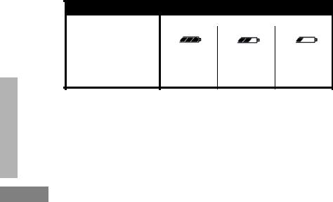
Battery Meter
The battery meter located in the upper left corner of the display indicates how much battery power you have remaining.
RDX Series™ Battery Meter
|
3 Bars |
2 Bars |
1 Bar |
|
Battery Type |
|
|
|
|
|
|
|
|
|
Li-Ion |
100%-70% |
70%-30% |
30%-0% |
|
AA |
100%-70% |
70%-30% |
30%-0% |
|
|
|
|
|
|
RADIO OVERVIEW
English 24
Charging the Battery
RDX Series™ offers two types of chargers :
•Standard Charger and,
•Rapid Charger.
The radio comes equipped with a Standard Charger.
To charge the battery (with the radio attached), place it in a Motorola-approved Drop-in Tray Single Unit Charger or Drop-in Tray Multi Unit Charger.
Note: When acquiring additional chargers or power supplies, make sure you have similar drop-in tray chargers and power supplies sets (all “rapid” or all “standard”). For part number details, refer to “Chargers” on page 88
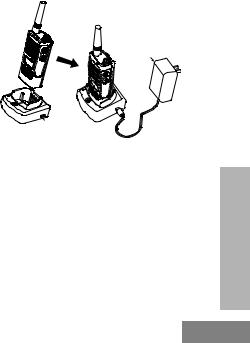
Charging with the Drop-in Tray
Single Unit Charger (SUC)
Power Supply (Transformer)
Drop-in Tray
Charger Port
1.Place the drop-in tray charger on a flat surface.
2.Insert the connector of the power supply into the port on the side of the drop-in tray charger.
3.Plug the AC adaptor into a power outlet.
4.Insert the radio into the tray with the front of the radio facing the front of the charger, as shown.
Note: When charging a battery attached to a radio, turn the radio OFF to ensure a full charge. See “Operational Safety Guidelines” on page 7 for more information
OVERVIEW RADIO
25 English
RADIO OVERVIEW
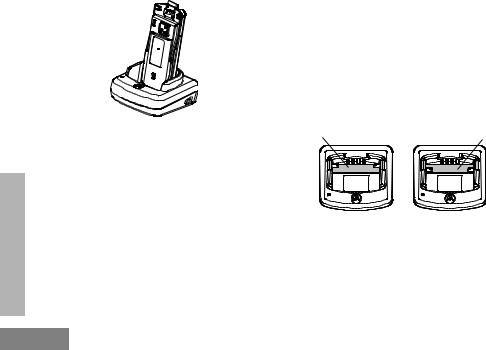
Charging a Standalone Battery
To charge only the battery - at step 4, insert the battery into the tray, with the inside surface of the battery facing the front of the charger, as shown. Ensure the slots in the battery correctly engage in the charger
Note: Ensure that the bracket in the charger is adjusted to the correct position for either Standard or High capacity battery. See “Charging a Standard Battery” on page 26
Charging a Standard Battery
The drop-in tray charger has a removable bracket that is adjustable depending on the type of battery that needs to be charged. It is designed to charge either the battery (with the radio) or a standalone battery. The drop-in tray charger's default position will charge a standard battery. The following image shows the orientation for each battery:
Adjustable bracket |
Adjustable bracket |
Standard |
High and Ultra High Capacity |
Figure 1: Identifying the Drop-In Charger’s Position Before Charging the Battery
English 26
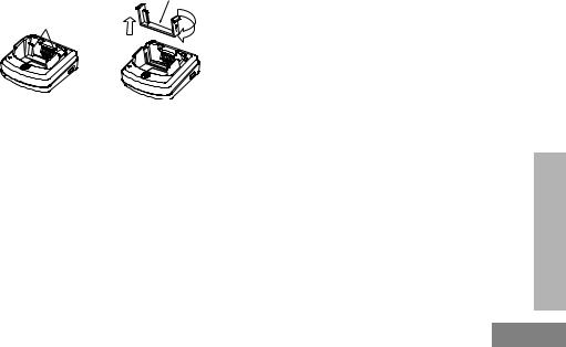
Charging a High Capacity or Ultra High Capacity Battery
|
Removable |
|
Piece |
Removable |
Turn around |
Piece |
horizontal |
|
180 degree |
3.Repeat same procedure to return to the charging a Standard Battery position. Label on the removable bracket should show ‘Standard Battery’ facing front.
Note: Make sure the bracket is assembled correctly for both standalone battery and battery (with radio)
To convert the charger from the default setup to accommodate the High capacity or Ultra High capacity battery:
1.Squeeze both tabs on each side of the removable bracket in the drop-in charger tray and lift the bracket from the charger tray.
2.Rotate the removable bracket 180 degrees and replace it by fitting it in the charger slot until it snaps. The label on the removable bracket should show ‘High & Ultra Capacity Battery’ facing front of the charger.
OVERVIEW RADIO
27 English

Drop-in Tray Charger LED Indicators
Standard Charger LED Indicator
Status |
LED Status |
Comments |
|
Power ON |
Steady red indication for 3 |
The charger has powered up |
|
seconds |
|
||
|
|
|
|
Charging |
Blinking red (slow) |
The charger is currently charging |
|
|
|
|
|
Charging |
Steady red indication |
Battery is fully charged |
|
Complete |
|
||
|
|
|
|
Battery Fault(*) |
Blinking red (fast) |
Battery had a fault when battery was inserted |
|
Notes: |
|
|
|
•(*) Normally re-seating the battery pack will correct this issue.
•(**) Battery temperature is too warm or too cold or wrong power supply is being used
RADIO OVERVIEW
English 28
Loading...