


PTP 300/500 Series
Deployment Guide
Contents |
|
Protect Your Installation .................................................................... |
2 |
Checklist, Site Survey and Tools ...................................................... |
4 |
Bench Test and Configuration - Pre and Post-Power Checks........... |
5 |
Bench Test and Configuration - Configuration Checks...................... |
6 |
Hoist & Safety Loop........................................................................... |
7 |
Mast Installation Instructions ............................................................. |
8 |
Wiring Diagram.................................................................................. |
9 |
Recommended Cable Specification ................................................ |
10 |
Cable and Gland Installation Notes................................................. |
12 |
Pre-Power Testing ........................................................................... |
13 |
Pre-Power Testing - Recording Resistance Values ......................... |
14 |
Post-Power Testing and Fault Finding............................................. |
15 |
Installation and Commissioning....................................................... |
16 |
Registration Warranty and Ordering Information............................. |
19 |
License Keys and Regulatory Information....................................... |
20 |
Protect Your Installation
Attention
ElectroMagnetic Discharge (Lightning)
Protect Your Installation!
EMD (Lightning) damage is not covered under warranty
The recommendations in this section and in the user manual, when followed correctly, give the installation the best protection from the harmful effects of EMD
However 100% protection is not implied or possible
The recommended components for protecting an installation are:
•Solid screen Ethernet cable: Superior Essex type BBDGE.
•Surge Arrestor: Type PTP-LPU - 2 per link – Part Number 2978
•Grounding Stake (if no suitable grounding point can be found).
•Minimum 8 AWG Grounding Cable
NB: There may be a local regulatory requirement to cross bond the CAT 5e cable to the mast at intervals as regular as every 10 metres (33 feet). This can be achieved using an Andrew grounding assembly type 223158 or similar.
We recommend that the practices and procedures detailed in the Motorola manual R56 "STANDARDS AND GUIDELINES FOR COMMUNICATION SITES" (68P81089E50) be applied to all new site build activities. For a copy on the manual please see your local Motorola representative. The manual can be downloaded from the Motorola Intranet site http://compass.mot.com/go/190860869
2
Protect Your Installation
Protection Requirements
Recommended |
NOT Recommended |
Recommended |
Zone A |
Zone A |
|
Zone B |
Zone B |
Zone B |
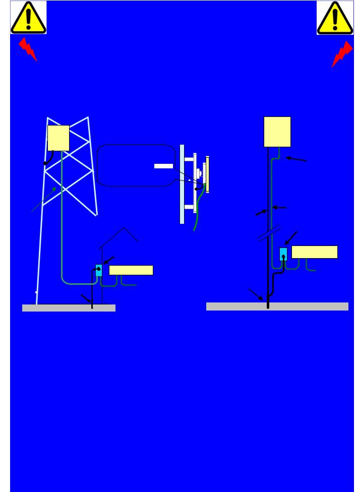
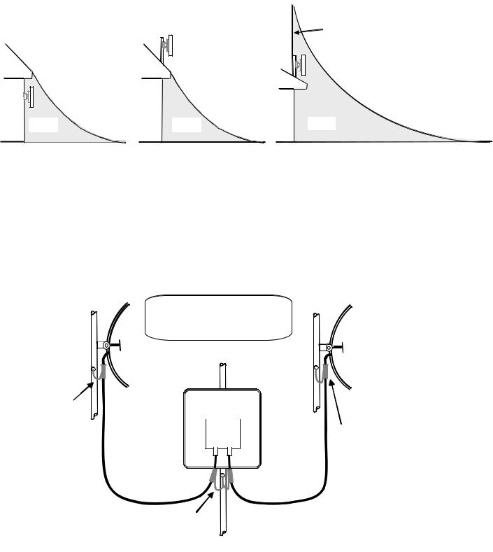
•Zone A – A direct strike is possible, mounting the ODU in this zone is not recommended.
•Zone B –Indirect EMD (Lightning) effects are still possible, however, mounting within
Zone B significantly reduces the possibility of a direct strike
For further explanation and connection details see User Guide section - Lightning Protection
Antenna cables should be grounded within 0.3 metres (1 foot) of the ODU and Antennas
Antenna Cable Grounded to Tower
Connectorized ODU |
Antenna Cable
Antenna Cables
Grounded to Tower
Antenna Cable Grounded
to Tower.
Antenna Cable
Note: Antenna cables grounded using an Andrew grounding assembly type 223158 or similar.
Additional Grounding Requirements for Connectorized ODU
3

Checklist, Site Survey and Tools
Before performing an installation of a Motorola PTP 300 or a PTP 500 Series system, ensure that you have read this entire guide and taken note of any safety information contained.
Checklist
•Check the contents of all packages against the packing list.
•Check the Web site for the latest software load.
List of special tools required
•13mm wrench and 22mm wrench for use with the glands.
•RJ45 Crimp Tool (Ensure you have the correct tool for the type of RJ45 being used).
•Personal Computer (PC) with 10, 100 or 1000BaseT Ethernet interface.
•Internet Explorer 6 or higher (recommended), or Firefox 2.0 or higher.
•Ethernet patch cables.
•Crimp tool for grounding lugs (only required when installing connectorized ODU).
•LINKPlanner report for this link.
Pre-installation – Site Survey— Link Planning
A site survey must be performed to identify all the obstructions (trees, buildings, etc) in the path and to assess the risk of interference. This information is important if you are to achieve an accurate link feasibility assessment.
The PTP 300 and the PTP 500 Series are designed to operate in Non-Line-of-Sight (NLoS) and Line-of-Sight (LoS) environments. Link planning enables a link of known quality to be installed. This involves the acquisition of path profile data (using Motorola’s free LINKPlanner utility). The LINKPlanner predicts data rates and reliability over the path. It allows the user to try different antenna heights and RF power settings. When the link is installed the mean path loss can be checked to confirm that the predicted data rate and link reliability is achievable. Motorola LINKPlanner is available to download from http://www.motorola.com/ptp/support
.
Pre-installation – License Keys and Regulatory Conformity
If the units have been purchased as a pair (link) then the License Keys (at the end of this guide or printed on a separate card in the box) will show how the units have been pre-configured to work as a link. Software, license key, unit’s IP address, subnet mask, gateway address, target address, master/slave and arming state are pre-configured.
Check that the Link is configured with the correct region Code, otherwise you will need to re-configure the units with Alternative License Keys before installing and commissioning the link. Please refer to Page 6, Step 12 for details on how to change the License Key.
4

Bench Testing (Optional) - Connect and Power Up
It is advised that the link be configured and tested on a bench before the final installation of the units on a pole or a mast. The following steps give details of how to connect an ODU to a PC in order to check the configuration details, change the IP settings or modify the license key. For the purpose of these tests, normal off-the-shelf Ethernet cables can be used.
Step 1: Connect the RJ45 at one end of a cable to the
ODU.
Step 4: Put the cover back and tighten the screw.
Step 2: Undo the retaining screw of the PIDU Plus and hinge back the cover.
Step 5: Plug in power lead using a cable appropriate for the installation.
Step 3: Plug in the ODU to PIDU Plus Cable ensuring that it snaps home.
NOTE - If the power LED does not illuminate, remove the power cable and the ODU connection from the PIDU Plus. Reconnect the power lead and check the power LED illumination (Green). If the power LED still does not light then check the power source.
Step 6: Connect a second
Ethernet cable (shown in yellow) to the “LAN” socket of the PIDU Plus.
Step 7: 30 seconds after powering, the Ethernet LED should be observed to flash slowly 10 times. If the Ethernet
LED does not illuminate (Orange), then either the PIDU
Plus or the cable to the ODU may be faulty. Replace cable and/or PIDU Plus and repeat from Step 1.
.
Step 8: Ensure PC is set to correct IP address 169.254.1.x, where 2 < x < 254. Connect the LAN cable to the PC (shown here in yellow).
Step 9: Check that the Ethernet
LED is now ON. Refer to the Troubleshooting section in this guide if the LED does not show any activity when accessing web pages.
5

Bench Testing (Optional) - Configuration Checks
Step 10: Use a web browser to connect to IP address http://169.254.1.1 for Slave and http://169.254.1.2 for Master units. Select ‘System Administration’ and ‘Login’. (The password will be empty for new units). We recommend that you change the password by selecting ‘Change Password’ in the Menu bar.
Step 11: You may wish to upgrade the software. If so, select ‘Software Upgrade’ and follow the on-screen instruction. Latest software is available from our web site: (http://motorola.motowi4solutions.com/software/#ptp)
Step 12: Check the License Key information and ensure you are using the correct Region Code. Otherwise, select ‘License
Key’ and replace with the alternative key supplied and reboot the unit.
Step 13: Access the ‘Installation Wizard’, ’Wireless Configuration’ page . Confirm the target MAC Address, Master Slave Mode and other configuration choices. Reboot the unit.
If testing connectorized ODUs, connect them together.
Repeat steps 1-13 for the paired unit and check that the status of the link shows UP on the ‘Status Page’.
6
 Loading...