


 Loading...
MTM5400
TETRA Mobile Terminal
Installation Manual
Publication Number
68015000181-B
When printed by Motorola |
@68015000181@ |
|
|
|
|

COPYRIGHT |
MTM5400 Mobile Terminal Installation Manual |
3 |
|
|
|
COPYRIGHT
Copyrights
© 2010 by Motorola Inc. All rights reserved.
No part of this manual may be reproduced, transmitted, stored in a retrieval system, or translated into any language or computer language, in any form or by any means, without the prior written permission of Motorola Inc.
Computer Software Copyrights
The Motorola products described in this manual may include copyrighted Motorola computer programs stored in semiconductor memories or other media. Laws in the United States and other countries preserve for Motorola certain exclusive rights for copyrighted computer programs including, but not limited to, the exclusive right to copy or reproduce in any form the copyrighted computer program. Accordingly, any copyrighted Motorola computer programs contained in the Motorola products described in this manual may not be copied, reproduced, modified, reverse-engineered, or distributed in any manner without the express written permission of Motorola. Furthermore, the purchase of Motorola products shall not be deemed to grant either directly or by implication, estoppel, or otherwise, any license under the copyrights, patents or patent applications of Motorola, except for the normal non-exclusive royalty-free license to use that arises by operation of law in the sale of a product.
Trademarks
Motorola, the Motorola Logo and all other trademarks identified as such herein are trademarks of Motorola Inc. All other product or service names are the property of their respective owners.
4 |
MTM5400 Mobile Terminal Installation Manual |
|
|
THIS PAGE INTENTIONALLY LEFT BLANK
Product Safety and RF Exposure |
MTM5400 Mobile Terminal Installation Manual |
5 |
|
|
|
IMPORTANT SAFETY INFORMATION
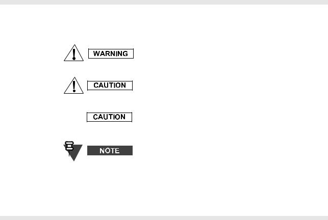
Icon Conventions
The signal word Warning with the associated safety icon implies information that, if disregarded, could result in death or serious injury, or serious product damage.
The signal word Caution with the associated safety icon implies information that, if disregarded, may result in minor or moderate injury, or serious product damage.
The signal word Caution may be used without the safety icon to state potential damage or injury that is not related to the product.
Notes contain information more important than the surrounding text, such as exceptions or preconditions. They also refer the reader elsewhere for additional information, remind the reader how to complete an action (when it’s not part of the current procedure, for instance), or tell the reader where something is located on the screen. There is no warning level associated with a Note.
Installation Requirements for Compliance with Radio Frequency (RF) Energy Exposure Safety Standards
ATTENTION!
This radio is intended for use in occupational/controlled conditions, where users have full knowledge of their exposure and can exercise control over their exposure to meet FCC limits. This radio device is NOT authorized for general population, consumer, or any other use.
To ensure compliance to RF Energy Safety Standards:
•Install only Motorola approved antennas and accessories.
•Be sure that Product Safety and RF Safety Booklet enclosed with this radio is available to the end user upon completion of the installation of this radio.
Before using this product, the operator must be familiar with the RF energy awareness information and operating instructions in the Product Safety and RF Exposure booklet enclosed with each radio (Motorola Publication part number 6804113J25 for APAC & LACR and 6866537D37 for EMEA) to ensure compliance with Radio Frequency (RF) energy exposure limits.
For a list of Motorola-approved antennas and other accessories, visit the following web site which lists approved accessories for your radio model.

6 |
MTM5400 Mobile Terminal Installation Manual |
Product Safety and RF Exposure |
|
|
|
ADDITIONAL IMPORTANT INFORMATION FOR
SERVICING AND INSTALLING THE TERMINAL
Only specialized workshops should be contacted for installation, maintenance and repair work.
This unit is equipped with protection fuses in the Power and Ignition Sense Cable. Replace these fuses only with the original ratings!
Failure to use correct manufacturer-approved parts may result in physical damage to this unit.
Fuse for Power Cable GKN6270/GKN6274: |
10A (Motorola Part Number: 6500139767) |
DOCUMENT HISTORY |
MTM5400 Mobile Terminal Installation Manual |
7 |
DOCUMENT HISTORY
The following major changes have been implemented in this manual since the previous edition:
Edition |
Description |
Date |
|
|
|
68015000181-A |
Initial edition |
Dec 2010 |
|
|
|
68015000181-B |
Toroid updates |
Dec 2010 |
|
|
|
8 |
MTM5400 Mobile Terminal Installation Manual |
THIS PAGE INTENTIONALLY LEFT BLANK
CONTENTS |
MTM5400 Mobile Terminal Installation Manual |
9 |
|
|
|
CONTENTS
COPYRIGHT. . . . . . . . . . . . . . . . . . . . . . . . . . . . . . . . . . . . . . . . . . . . . . . . . . 3
Copyrights . . . . . . . . . . . . . . . . . . . . . . . . . . . . . . . . . . . . . . . . . . . . . . . . . . . . . . . . . 3
Computer Software Copyrights . . . . . . . . . . . . . . . . . . . . . . . . . . . . . . . . . . . . . . . . 3
Trademarks . . . . . . . . . . . . . . . . . . . . . . . . . . . . . . . . . . . . . . . . . . . . . . . . . . . . . . . . 3
IMPORTANT SAFETY INFORMATION . . . . . . . . . . . . . . . . . . . . . . . . . . . . . 5
Icon Conventions . . . . . . . . . . . . . . . . . . . . . . . . . . . . . . . . . . . . . . . . . . . . . . . . . . . 5
Installation Requirements for Compliance with Radio Frequency (RF) Energy Exposure Safety Standards . . . . . . . . . . . . . . . . . . . . . . . . . . . . . . . . . . . . . . . . . . . 5
Additional Important Information for Servicing and Installing the Terminal. . . . 6
DOCUMENT HISTORY. . . . . . . . . . . . . . . . . . . . . . . . . . . . . . . . . . . . . . . . . . 7
CONTENTS . . . . . . . . . . . . . . . . . . . . . . . . . . . . . . . . . . . . . . . . . . . . . . . . . . 9
SCOPE . . . . . . . . . . . . . . . . . . . . . . . . . . . . . . . . . . . . . . . . . . . . . . . . . . . . . 13
Scope of This Manual. . . . . . . . . . . . . . . . . . . . . . . . . . . . . . . . . . . . . . . . . . . . . . . 13
MTM5400 Manuals and User Guides. . . . . . . . . . . . . . . . . . . . . . . . . . . . . . . . . . . . . . . . 14
Warranty and Service Support. . . . . . . . . . . . . . . . . . . . . . . . . . . . . . . . . . . . . . . . . . . 15
Service Information . . . . . . . . . . . . . . . . . . . . . . . . . . . . . . . . . . . . . . . . . . . . . . . . 16
Europe, Middle East and Africa Region . . . . . . . . . . . . . . . . . . . . . . . . . . . . . . . . . . . . . . 16 EMEA Systems Support Centre (ESSC) . . . . . . . . . . . . . . . . . . . . . . . . . . . . . . . . . . . 16 EMEA Systems Component Centre (ESCC) . . . . . . . . . . . . . . . . . . . . . . . . . . . . . . . . 16 Parts Identification and Ordering . . . . . . . . . . . . . . . . . . . . . . . . . . . . . . . . . . . . . . . . . 17 EMEA Test Equipment Support. . . . . . . . . . . . . . . . . . . . . . . . . . . . . . . . . . . . . . . . . . 17 Your Input . . . . . . . . . . . . . . . . . . . . . . . . . . . . . . . . . . . . . . . . . . . . . . . . . . . . . . . . . . 17 Updated Versions of this Manual. . . . . . . . . . . . . . . . . . . . . . . . . . . . . . . . . . . . . . . . . 17
Asia, Pacific Region . . . . . . . . . . . . . . . . . . . . . . . . . . . . . . . . . . . . . . . . . . . . . . . . . . . . . 18 Piece Parts . . . . . . . . . . . . . . . . . . . . . . . . . . . . . . . . . . . . . . . . . . . . . . . . . . . . . . . . . 18 Technical Support . . . . . . . . . . . . . . . . . . . . . . . . . . . . . . . . . . . . . . . . . . . . . . . . . . . . 18 Further Assistance from Motorola . . . . . . . . . . . . . . . . . . . . . . . . . . . . . . . . . . . . . . . . 18 Parts Identification and Ordering . . . . . . . . . . . . . . . . . . . . . . . . . . . . . . . . . . . . . . . . . 18
Latin America Region . . . . . . . . . . . . . . . . . . . . . . . . . . . . . . . . . . . . . . . . . . . . . . . . . . . . 19
MODEL INFORMATION & ACCESSORIES . . . . . . . . . . . . . . . . . . . . . . . . 21
MTM5400 Mobile Terminal Model Information . . . . . . . . . . . . . . . . . . . . . . . . . . . 21
Sales Model Nomenclature . . . . . . . . . . . . . . . . . . . . . . . . . . . . . . . . . . . . . . . . . . 21
10 |
MTM5400 Mobile Terminal Installation Manual |
CONTENTS |
|
|
|
Model Specifications* . . . . . . . . . . . . . . . . . . . . . . . . . . . . . . . . . . . . . . . . . . . . . . . . . . . . 22
Model Descriptions** . . . . . . . . . . . . . . . . . . . . . . . . . . . . . . . . . . . . . . . . . . . . . . . . . . . . . 22
Accessories-to-Model Chart . . . . . . . . . . . . . . . . . . . . . . . . . . . . . . . . . . . . . . . . . . . . . . . 23
INSTALLATION . . . . . . . . . . . . . . . . . . . . . . . . . . . . . . . . . . . . . . . . . . . . . . 27
Introduction . . . . . . . . . . . . . . . . . . . . . . . . . . . . . . . . . . . . . . . . . . . . . . . . . . . . . . .27
General Information. . . . . . . . . . . . . . . . . . . . . . . . . . . . . . . . . . . . . . . . . . . . . . . . . . . . . . 27
DC Power Cable Installation. . . . . . . . . . . . . . . . . . . . . . . . . . . . . . . . . . . . . . . . . .28
Installation Planning. . . . . . . . . . . . . . . . . . . . . . . . . . . . . . . . . . . . . . . . . . . . . . . . . . . . . . 28
Installation Procedure . . . . . . . . . . . . . . . . . . . . . . . . . . . . . . . . . . . . . . . . . . . . . . . . . . . . 29
Terminal Installation . . . . . . . . . . . . . . . . . . . . . . . . . . . . . . . . . . . . . . . . . . . . . . . .31
Enhanced Control Head Installation . . . . . . . . . . . . . . . . . . . . . . . . . . . . . . . . . . . . . . . . . 31 Trunnion Installation . . . . . . . . . . . . . . . . . . . . . . . . . . . . . . . . . . . . . . . . . . . . . . . . . . . . . 32 Installation Planning . . . . . . . . . . . . . . . . . . . . . . . . . . . . . . . . . . . . . . . . . . . . . . . . . . . 32 Installation Procedure . . . . . . . . . . . . . . . . . . . . . . . . . . . . . . . . . . . . . . . . . . . . . . . . . . 33 Dashboard Installation. . . . . . . . . . . . . . . . . . . . . . . . . . . . . . . . . . . . . . . . . . . . . . . . . . . . 34 Installing the Radio in an Automotive Dashboard . . . . . . . . . . . . . . . . . . . . . . . . . . . . . 34 Mounting the Radio in the Frame . . . . . . . . . . . . . . . . . . . . . . . . . . . . . . . . . . . . . . . . . 35 Remove the Radio from the Frame. . . . . . . . . . . . . . . . . . . . . . . . . . . . . . . . . . . . . . . . 37 Desktop Installation . . . . . . . . . . . . . . . . . . . . . . . . . . . . . . . . . . . . . . . . . . . . . . . . . . . . . . 38 Planning . . . . . . . . . . . . . . . . . . . . . . . . . . . . . . . . . . . . . . . . . . . . . . . . . . . . . . . . . . . . 38 Installation. . . . . . . . . . . . . . . . . . . . . . . . . . . . . . . . . . . . . . . . . . . . . . . . . . . . . . . . . . . 38 Remote Mount Installation. . . . . . . . . . . . . . . . . . . . . . . . . . . . . . . . . . . . . . . . . . . . . . . . . 40 Installing the Remote Mount Enhanced Control Head onto the Remote Mount Trunnion
41
Installing the Remote Mount Enhanced Control Head in a DIN Mount Bracket . . . . . . 42 Inserting the Remote Mount Enhanced Control Head with the DIN Mount Bracket into the DIN Frame . . . . . . . . . . . . . . . . . . . . . . . . . . . . . . . . . . . . . . . . . . . . . . . . . . . . . . . . . . 43 Adding Extra Connectivity to the Remote Head . . . . . . . . . . . . . . . . . . . . . . . . . . . . . . 44 Installing the Accessories Expansion Cable . . . . . . . . . . . . . . . . . . . . . . . . . . . . . . . . . 44
Motorcycle Mount Enhanced Control Head Installation. . . . . . . . . . . . . . . . . . . . . . . . . . . 45 Planning . . . . . . . . . . . . . . . . . . . . . . . . . . . . . . . . . . . . . . . . . . . . . . . . . . . . . . . . . . . . 45 Installing the Motorcycle Mount Enhanced Control Head . . . . . . . . . . . . . . . . . . . . . . . 46 Mechanical Parts . . . . . . . . . . . . . . . . . . . . . . . . . . . . . . . . . . . . . . . . . . . . . . . . . . . . . 48 Installation of the Motorcycle Mount TELCO Cable (PMKN4030) . . . . . . . . . . . . . . . . 48 Adding Extra Connectivity to the Motorcycle Mount Enhanced Control Head . . . . . . . 48
Data Expansion Head Enhanced Installation . . . . . . . . . . . . . . . . . . . . . . . . . . . .49
Data Expansion Head Enhanced Radio without Control Head . . . . . . . . . . . . . . . . . . . . . 49 Data Expansion Head Enhanced with 3rd Party Control Head . . . . . . . . . . . . . . . . . . . . . 50 Data Box Radio . . . . . . . . . . . . . . . . . . . . . . . . . . . . . . . . . . . . . . . . . . . . . . . . . . . . . . . . . 51 Junction Box Installation . . . . . . . . . . . . . . . . . . . . . . . . . . . . . . . . . . . . . . . . . . . . . . . . . . 52 General . . . . . . . . . . . . . . . . . . . . . . . . . . . . . . . . . . . . . . . . . . . . . . . . . . . . . . . . . . . . . 52 Installation. . . . . . . . . . . . . . . . . . . . . . . . . . . . . . . . . . . . . . . . . . . . . . . . . . . . . . . . . . . 52 Service . . . . . . . . . . . . . . . . . . . . . . . . . . . . . . . . . . . . . . . . . . . . . . . . . . . . . . . . . . . . . 53 Connections . . . . . . . . . . . . . . . . . . . . . . . . . . . . . . . . . . . . . . . . . . . . . . . . . . . . . . . . . 53
CONTENTS |
MTM5400 Mobile Terminal Installation Manual |
11 |
|
|
|
Connection Plan for the Junction Box Accessory Terminal . . . . . . . . . . . . . . . . . . . . . 54 Connection Plan for Accessory Connector Kit (HLN9457) . . . . . . . . . . . . . . . . . . . . . 56
Connectors and Pin Assignment of the Radio. . . . . . . . . . . . . . . . . . . . . . . . . . . 58
Transceiver Rear Side - Pin Function. . . . . . . . . . . . . . . . . . . . . . . . . . . . . . . . . . . . . . . . 58
Accessory Connection Plan . . . . . . . . . . . . . . . . . . . . . . . . . . . . . . . . . . . . . . . . . . . . . . . 60
Re-crimp Procedure. . . . . . . . . . . . . . . . . . . . . . . . . . . . . . . . . . . . . . . . . . . . . . . . . . . 61
Connectors and Pin Assignment of Data Expansion Head Enhanced and Remote Head Enhanced. . . . . . . . . . . . . . . . . . . . . . . . . . . . . . . . . . . . . . . . . . . . . 62
10-Pin TELCO Connector . . . . . . . . . . . . . . . . . . . . . . . . . . . . . . . . . . . . . . . . . . . . . . 62 25-Pin subD Connector . . . . . . . . . . . . . . . . . . . . . . . . . . . . . . . . . . . . . . . . . . . . . . . . 63 9-Pin subD Connector . . . . . . . . . . . . . . . . . . . . . . . . . . . . . . . . . . . . . . . . . . . . . . . . . 64
Connector and Pin Assignment of the Enhanced Control Head . . . . . . . . . . . . 65 Connecting Cables . . . . . . . . . . . . . . . . . . . . . . . . . . . . . . . . . . . . . . . . . . . . . . . . . 68
Motorcycle Mount Enhanced Control Head-to-Remote Head Enhanced/Data Expansion Head Enhanced (Motorcycle Mount TELCO Cable) . . . . . . . . . . . . . . . . . . . . . . . . . . . . 68 Remote Mount Enhanced Control Head/Motorcycle Mount Enhanced Control Head-to- Accessories (Accessories Expansion Cable) . . . . . . . . . . . . . . . . . . . . . . . . . . . . . . . . . . 69 Radio-to-Junction Box . . . . . . . . . . . . . . . . . . . . . . . . . . . . . . . . . . . . . . . . . . . . . . . . . . . 71 Data Expansion Head Enhanced Radio-to-Data Device . . . . . . . . . . . . . . . . . . . . . . . . . 72 Data Expansion Head Enhanced Radio-to-Fist Microphone . . . . . . . . . . . . . . . . . . . . . . 73
Operation. . . . . . . . . . . . . . . . . . . . . . . . . . . . . . . . . . . . . . . . . . . . . . . . . . . . . . . . . . . 73 Making Connections . . . . . . . . . . . . . . . . . . . . . . . . . . . . . . . . . . . . . . . . . . . . . . . . . . 73 Removing the Existing Coiled Cord Cable. . . . . . . . . . . . . . . . . . . . . . . . . . . . . . . . . . 73 Radio-to-Data Device: Active Data Cable . . . . . . . . . . . . . . . . . . . . . . . . . . . . . . . . . . . . 75 Cable Connectivity. . . . . . . . . . . . . . . . . . . . . . . . . . . . . . . . . . . . . . . . . . . . . . . . . . . . 75
Vehicle Antenna Installation . . . . . . . . . . . . . . . . . . . . . . . . . . . . . . . . . . . . . . . . . 76
Mobile Radio Operation and EME Exposure . . . . . . . . . . . . . . . . . . . . . . . . . . . . . . . . . . 76
Selecting an Antenna Site . . . . . . . . . . . . . . . . . . . . . . . . . . . . . . . . . . . . . . . . . . . . . . . . 76
Antenna Installation Procedure . . . . . . . . . . . . . . . . . . . . . . . . . . . . . . . . . . . . . . . . . . . . 77
Completing the Installation . . . . . . . . . . . . . . . . . . . . . . . . . . . . . . . . . . . . . . . . . . . . . . . . 77
External Speaker Installation. . . . . . . . . . . . . . . . . . . . . . . . . . . . . . . . . . . . . . . . . 78
APPENDIX . . . . . . . . . . . . . . . . . . . . . . . . . . . . . . . . . . . . . . . . . . . . . . . . . . 79
Product Specific Information. . . . . . . . . . . . . . . . . . . . . . . . . . . . . . . . . . . . . . . . . 79
Equipment Electrical Ratings . . . . . . . . . . . . . . . . . . . . . . . . . . . . . . . . . . . . . . . . . . . . . . 79
Normal Load Conditions. . . . . . . . . . . . . . . . . . . . . . . . . . . . . . . . . . . . . . . . . . . . . . . . . . 79
Fuse Identification . . . . . . . . . . . . . . . . . . . . . . . . . . . . . . . . . . . . . . . . . . . . . . . . . . . . . . 80
12 |
MTM5400 Mobile Terminal Installation Manual |
|
|
THIS PAGE INTENTIONALLY LEFT BLANK

SCOPE |
MTM5400 Mobile Terminal Installation Manual |
13 |
|
|
|
SCOPE
Scope of This Manual
This manual is intended for use by service technicians familiar with similar types of equipment. It contains information required for the installation of the equipment described and is current as of the printing date. Changes which occur after printing date may be incorporated by a complete Manual revision or alternatively as additions.
The mobile terminal has to be installed by trained service personnel only.
All installations should take place in accordance with the requirements of the vehicle and antenna manufacturer/supplier.
This manual is divided into the following sections:
•Safety and General Information
•Document History
•Contents
•Scope of this manual
•Model Information
•Installation
•APPENDIX Product Specific Information

14 |
MTM5400 Mobile Terminal Installation Manual |
SCOPE |
MTM5400 Manuals and User Guides
Installation Instructions
68015000181 MTM5400 Installation Manual (English)
68015000603 MTM5400 Installation Manual (English/German)
Service Manual
68015000183 MTM5400 / MTM800 FuG Basic Service Manual EMEA (English) 68015000587 MTM5400 Basic Service Manual APAC (English)
Quick Start Guides
68015000289 MTM5400 Quick Start Guide (English)
68015000290 MTM5400 Quick Start Guide (Spanish)
68015000291 MTM5400 Quick Start Guide (Norwegian)
68015000292 MTM5400 Quick Start Guide (Dutch)
68015000293 MTM5400 Quick Start Guide (German)
68015000294 MTM5400 Quick Start Guide (Polish)
68015000295 MTM5400 Quick Start Guide (Italian)
68015000296 MTM5400 Quick Start Guide (French)
68015000297 MTM5400 Quick Start Guide (Danish)
68015000298 MTM5400 Quick Start Guide (Swedish)
68015000288 MTM5400 Quick Start Guide (Traditional Chinese)
68015000287 MTM5400 Quick Start Guide (Simplified Chinese)
68015000286 MTM5400 Quick Start Guide (Korean)
68015000285 MTM5400 Quick Start Guide (Arabic)
68015000284 MTM5400 Quick Start Guide (Lithuanian)
User Guides
68015000180 MTM5400 Feature User Guide (English)
68015000186 MTM5400 Feature User Guide (English/German)
Safety Leaflets
6804113J25 Mobile Safety Leaflet (APAC & LACR)
6866537D37 Mobile Safety Leaflet (EMEA)
SCOPE |
MTM5400 Mobile Terminal Installation Manual |
15 |
|
|
|
Warranty and Service Support
Motorola offers long term support for its products. This support includes full exchange and/or repair of the product during the warranty period, and service/ repair or spare parts support out of warranty. Prior to shipping any terminal back to the appropriate Motorola warranty depot, please contact Customer Resources or your Motorola dealer, distributor or reseller.
All returns must be accompanied by a Warranty Claim Form, available from your Customer Service representative or Motorola Online Extranet (MOL) or your Motorola dealer, distributor or reseller.
Warranty Period and Return Instructions
The terms and conditions of warranty are defined fully in the Motorola Customer, Dealer or Distributor or Reseller contract. These conditions may change from time to time and the following notes are for guidance purposes only.
In instances where the product is covered under a "return for replacement" or "return for repair" warranty, a check of the product should be performed prior to shipping the unit back to Motorola. This is to ensure that the product has been correctly programmed or has not been subjected to damage outside the terms of the warranty.
Prior to shipping any terminal back to the appropriate Motorola warranty depot, please contact Customer Resources (please refer to following pages). All returns must be accompanied by a Warranty Claim Form, available from your Customer Services representative. Products should be shipped back in the original packaging, or correctly packaged to ensure no damage occurs in transit.
After Warranty Period
After the Warranty period, Motorola continues to support its products in two ways.
•Motorola's Regional Radio Support Centres offer a repair service to both end users and dealers at competitive prices.
•AAD supplies individual parts and modules that can be purchased by dealers who are technically capable of performing fault analysis and repair.

16 |
MTM5400 Mobile Terminal Installation Manual |
SCOPE |
|
|
|
|
|
|
|
|
|
|
|
|
|
Service Information
Europe, Middle East and Africa Region
EMEA Systems Support Centre (ESSC)
The EMEA Systems Support Centre provides a remote Technical Support Service to help customers resolve technical issues and quickly restore networks and systems. This team of highly skilled professionals is available to customers with current service agreements in place that include the Technical Support Service. The ESSC technical experts may be accessed through the EMEA Integrated Call Center either electronically or using the telephone numbers listed below. If you are unsure as to whether or not your current service agreement entitles you to benefit from this service, or if you would like more information about the Technical Support Service, please contact your local customer support or account manager for further information.
Contact details:
Email: ESSC@motorolasolutions.com
List of Telephone Numbers:
Country |
In Country Number to Dial |
|
|
Austria |
01206091087 |
|
|
Denmark |
043682114 |
|
|
France |
0157323434 |
|
|
Germany |
06950070204 |
|
|
Italy |
0291483230 |
|
|
Lithuania |
880 030 828 |
|
|
Netherlands |
0202061404 |
|
|
Norway |
24159815 |
|
|
Portugal |
0217616160 |
|
|
Russia |
810 800 228 41044 (Alternative 810 800 120 1011) |
|
|
Saudi Arabia |
800 844 5345 |
|
|
South Africa |
0800981900 |
|
|
Spain |
0912754787 |
|
|
United Kingdom |
02030 277499 |
|
|
It is recommended that access from any other country uses: +44 2030 277499
EMEA Systems Component Centre (ESCC)
The European Systems Component Centre provides a repair service for infrastructure equipment. Customers requiring repair service should contact the Customer Information Desk to obtain a Return Material Authorisation number. The equipment should then be shipped to the following address unless advised otherwise.
SCOPE |
MTM5400 Mobile Terminal Installation Manual |
17 |
|
|
|
Motorola GmbH, European Systems Component Centre, Am Borsigturm 130, 13507 Berlin, Germany
Contact details:
Email: ESCC.admin@motorolasolutions.com
Telephone Number: +49 30 66861555
Fax: +49 30 66861426
Mon - Fri 08:00 am to 06:00 pm (CET)
Parts Identification and Ordering
Request for help in identification of non-referenced spare parts should be directed to the Customer Care Organization of Motorola’s local area representation. Orders for replacement parts, kits and assemblies should be placed directly on Motorola’s local distribution organization or via the Extranet site Motorola Online at https://emeaonline.motorola.com.
EMEA Test Equipment Support
Information related to support and service of Motorola Test Equipment is available by calling the Motorola Test Equipment Service Group in Germany at +49 (0) 6128 702179, Telefax +49 (0) 6128 951046, through the Customer Care Organization of Motorola’s local area representation, or via the Internet at http://www.gd-decisionsystems.com/cte/.
Your Input
...is much appreciated. If you have any comments, corrections, suggestions or ideas for this publication or any other requirements regarding Motorola publications, please send an e-mail to doc.emea@motorola.com.
Updated Versions of this Manual
...are available at our Extranet site Motorola Online. Contact us at doc.emea@motorola.com for access.

18 |
MTM5400 Mobile Terminal Installation Manual |
SCOPE |
|
|
|
Asia, Pacific Region
Piece Parts
Some replacement parts, spare parts, and/or product information can be ordered directly. If a complete Motorola part number is assigned to the part, it is available from Motorola Radio Aftermarket and Accessory Division (AAD). If no part number is assigned, the part is not normally available from Motorola. If a parts list is not included, this generally means that no user-serviceable parts are available for that kit or assembly.
Note on this digital TETRA Terminal: The CPS has no capability to tune the terminal. Tuning the terminal can only be performed at the factory or at the appropriate Motorola Repair Centre. Component replacement can affect the terminal tuning and must only be performed by the appropriate Motorola Repair Centre.
All orders for parts/information should include the complete Motorola identification number. All part orders should be directed to your local AAD office. Please refer to your latest price pages.
Technical Support
Technical support is available to assist the dealer/distributor in resolving any malfunction which may be encountered. Initial contact should be by telephone wherever possible.
When contacting Motorola Technical Support, be prepared to provide the product model number and the unit’s serial number.
Further Assistance from Motorola
You can also contact the Customer Help Desk through the following web address:
http://www.motorola.com/tetra.
Parts Identification and Ordering
Request for help in identification of non-referenced spare parts should be directed to the Customer Care Organization of Motorola’s local area representation. Orders for replacement parts, kits and assemblies should be placed directly on Motorola’s local distribution organization or via Motorola Online (Extranet).

SCOPE |
MTM5400 Mobile Terminal Installation Manual |
19 |
|
|
|
Latin America Region
Latin America Radio Support Centres
The Customer Support is available through the following service centres:
Warranty and Repairs:
MOTOROLA DE COLOMBIA SERVICE CENTRE
Torre Banco Ganadero Carrera 7 No. 71-52 Torre B piso 13 Oficina 1301
Bogota - Colombia (571) 376-6990
MOTOROLA DE MEXICO SERVICE CENTRE
Bosques de Alisos #125 Col. Bosques de las Lomas CP 05120 Mexico DF 5252576700
Piece Parts:
To order parts in Latin America and the Caribbean contact your local Motorola CGISS representative.
MOTOROLA, INC.
Latin American Countries Region
789 International Parkway
Sunrise, FL 33325
USA 954-723-8959
MOTOROLA DE ARGENTINA
Ave. del Libertador 1855 B1638BGE, Vicente Lopez Buenos Aires, Argentina 5411-4317-5300
MOTOROLA DE LOS ANDES C.A.
Ave. Francisco de Miranda Centro Lido, Torre A
Piso 15, El Rosal Caracas, 1060 Venezuela 58212-901-4600
MOTOROLA DO BRASIL LTDA.
Av. Chedid Jafet
222 Bloco D Conjuntos 11,12,21,22 E 41 Condominio Millennium Office Park 04551-065- Vila Olimpia, Sao Paulo Brasil
5511-3847-668
MOTOROLA CHILE
Ave. Nueva Tajamar 481 Edif. World Trade Center Of. 1702, Torre Norte Las Condes
Santiago, Chile 562-338-9000
MOTOROLA DE COLOMBIA, LTDA.
Carrera 7 #71-52 Torre A, Oficina 1301 Bogotá, Colombia 571-376-6990
MOTOROLA DE COSTA RICA
Parque Empresarial Plaza Roble Edificio El Portico, 1er Piso Centro de Negocios Internacional Guachepelin, Escazu
San Jose, Costa Rica 506-201-1480
MOTOROLA DEL ECUADOR
Autopist Gral. Rumiñahui, Puente 2 Conjunto Puerta del Sol Este-Ciudad Jardin Pasa E, Casa 65
Quito, Ecuador 5932-264-1627
MOTOROLA DE MEXICO, S.A.
Calle Bosques de Alisos #125 Col. Bosques de Las Lomas 05120 México D.F.
México 52-555-257-6700
MOTOROLA DEL PERU, S.A.
Ave. República de Panama 3535 Piso 11, San Isidro
Lima 27, Peru 511-211-0700
Technical Support:
https://businessonline.motorola.com, go to Contact Us to request technical support
Some replacement parts, spare parts, and/or product information can be ordered directly. If a complete Motorola part number is assigned to the part, it is available from Motorola. If no part number is assigned, the part is not normally available from Motorola. If the part number is appended with an asterisk, the part is serviceable by Motorola Depot only. If a parts list is not included, this generally means that no user-serviceable parts are available for that kit or assembly.
20 |
MTM5400 Mobile Terminal Installation Manual |
|
|
THIS PAGE INTENTIONALLY LEFT BLANK
MODEL INFORMATION & ACCESSORIES |
MTM5400 Mobile Terminal Installation Manual |
21 |
|
|
|
MODEL INFORMATION & ACCESSORIES
MTM5400 Mobile Terminal Model Information
This manual applies to the following Mobile Terminal Models
|
Type No. |
Sales Model No. |
Short Description |
Model |
|
|
|
|
|
|
|
|
MT953C |
M83PFS6TZ5AN |
MTM5400 380-430MHz, DASH |
M1 |
|
|
|
|
|
|
|
|
MT953C |
M83PFS6TZ4AN |
MTM5400 380-430MHz, DESK |
M2 |
|
|
|
|
|
|
|
|
MT953C |
M83PFS6TZ6AN |
MTM5400 380-430 MHz, REMOTE |
M3 |
|
|
|
|
|
|
|
|
MT953C |
M83PFS6TZ2AN |
MTM5400 380-430 MHz, M’CYCLE |
M4 |
|
|
|
|
|
|
|
|
MT953C |
M83PFA6TZ5AN |
MTM5400 380-430 MHz, DATA |
M5 |
|
|
|
|
|
|
|
|
|
|
|
|
|
|
|
|
|
|
|
Sales Model Nomenclature
Position: |
1 |
2 |
3 |
4 |
5 |
6 |
7 |
8 |
9 |
10 |
11 |
12 |
Typical Model Number: |
M |
8 |
3 |
P |
F |
S |
6 |
T |
Z |
5 |
A |
N |
Type of Unit
M = Mobile Product
Model Series
83 = MTM5400
Frequency Band
M = 260 - 275 MHz
N = 350 - 390 MHz
P = 380 - 430 MHz
R = 410 - 470 MHz
U = 806 - 870 MHz
Level
F = 10.0 Watts
Physical Packages
S = Enhanced Control Head
A = Data Box (No Control Head)
Channel Spacing
6 = 20/25 kHz
Unique Variation
N = Standard Package
Version Letter
Feature Level
5 = Dash/Data Mount
4 = Desk Mount
2 = Motorcycle Mount
6 = Remote Mount
Primary System Type
Z = TETRA
Primary Operation
T = Trunking

22 MTM5400 Mobile Terminal Installation Manual MODEL INFORMATION & ACCESSORIES
Model Specifications*
GENERAL |
|
RECEIVER |
|
TRANSMITTER |
||
|
|
|
|
|
|
|
ETSI: |
ETS 300 394-1 |
Receiver Type: |
|
Direct |
Modulation Type: |
π/4DQPSK |
|
ETS 300 489-1 |
|
|
Conversion |
|
|
Type Number: |
|
Frequency Range: |
|
|
RF Power: |
|
MTM5400 380-430 MHz |
MT953C |
MTM5400 |
380-430 MHz |
TMO |
10W / 40dBm |
|
|
|
|
|
|
DMO |
10W / 40dBm |
Temperature Range for Transceiver: |
Channel Spacing: |
|
25 kHz |
Frequency Range TMO: |
|
|
Operating |
-30°C to +60°C |
Sensitivity (3.5%) BER: |
|
-114.5 |
MTM5400 |
380-430 MHz |
Storage: |
-40°C to +85°C |
|
|
dBm |
|
|
Power Supply: |
|
|
|
|
Frequency Range DMO: |
|
Minimum: |
10.8 Vdc |
Intermodulation: |
|
-47 dBm |
|
|
Nominal: |
13.2 Vdc |
|
|
|
MTM5400 |
380-430 MHz |
Maximum: |
15.6 Vdc |
Blocking (50-100 kHz): |
|
-40 dBm |
|
|
Max. Current |
Approx. 4.5 A |
|
|
|
|
|
Dimensions (HxWxD) in mm: |
|
Spurious Rejection: |
|
-45 dBm |
Frequency Stability: |
|
Transceiver with |
|
Adjacent Channel |
|
|
Locked to Base |
+/-100 Hz |
Enhanced Control Head, |
|
Interference Ratio: |
|
-45 dB |
Not Locked to Base |
+/- 1 kHz |
Dash Mount |
60 x 188 x 198 |
|
|
|
|
|
Weight in grams: |
|
Frequency Stability: |
|
|
Spurious Emissions: |
|
Transceiver with |
|
Locked to Base |
|
+/-100 Hz |
Conducted/Radiated |
- 36 dBm <=1GHz |
Enhanced Control Head, |
|
Unlocked to Base |
|
+/- 1 kHz |
|
- 30 dBm > 1GHz |
Dash Mount |
1500 |
|
|
|
|
|
GPS Performance |
|
Audio Rated (@4 Ohms): |
|
Adjacent Channel Power Ratio |
||
Autonomous Acquisition |
-143 dBm / |
For External Speaker: |
|
10 W |
(@ ± 25kHz) |
|
Sensitivity |
-173 dBW |
Distortion at Rated Audio: |
5% Max. |
|
|
|
|
|
|
|
|
380-430 MHz |
- 60 dBc |
Tracking Sensitivity |
-159 dBm / |
|
|
|
|
|
|
- 189 dBW |
|
|
|
|
|
|
|
|
|
|
|
|
*) Technical information may be subject to change without further notice.
Model Descriptions**
Model |
Description |
|
|
|
|
M1 |
Dash Mount with Mobile Terminal with Direct Mount Enhanced Control Head, Speaker, Microphone or |
|
Handset, Standard User Guide, and Installation Accessories. |
||
|
||
|
|
|
M2 |
Desk Mount with Mobile Terminal with Direct Mount Enhanced Control Head, Speaker, Microphone or |
|
Handset, Standard User Guide, Installation Accessories and Tray with a Power Supply. |
||
|
||
|
|
|
|
Remote Mount with Mobile Terminal with Remote Mount Enhanced Control Head, optional either with |
|
M3 |
Remote Head Enhanced or Data Expansion Head Enhanced, Speaker, Microphone or Handset, Remote |
|
|
Mount cables, Standard User Guide, and Installation Accessories. |
|
|
|
|
|
Motorcycle Mount with Mobile Terminal with Motorcycle Mount Enhanced Control Head, optional either with |
|
M4 |
Remote Head Enhanced or Data Expansion Head Enhanced, Speaker, Microphone or Handset, Motorcycle |
|
cables, Standard User Guide, and Installation Accessories; Audio Accessories, Standard User Guide, and |
||
|
||
|
Installation Accessories. |
|
|
|
|
M5 |
Data Box - Remote Mount Configuration with Expansion Head Enhanced, without Enhanced Control Head, |
|
Remote Mount cables, Standard User Guide, Installation Accessories, and a Power Supply. |
||
|
||
|
|
**) Other combinations are not recommend or not possible.

MODEL INFORMATION & ACCESSORIES MTM5400 Mobile Terminal Installation Manual 23
Accessories-to-Model Chart
ACCESSORIES
Control Heads |
Part Number |
M1 |
M2 |
M3 |
M4 |
M5 |
|
|
|
|
|
|
|
Control Head, Roman Keypad |
PMWN4009 |
X |
X |
|
|
|
|
|
|
|
|
|
|
Control Head, Arabic Keypad |
PMWN4012 |
X |
X |
|
|
|
|
|
|
|
|
|
|
Control Head, Cyrillic Keypad |
PMWN4014 |
X |
X |
|
|
|
|
|
|
|
|
|
|
Control Head Hungarian Keypad |
PMWN4015 |
X |
X |
|
|
|
|
|
|
|
|
|
|
Control Head Hebrew Keypad |
PMWN4016 |
X |
X |
|
|
|
|
|
|
|
|
|
|
Remote Mount Control Head, Roman Keypad |
PMWN4017 |
|
|
X |
|
|
|
|
|
|
|
|
|
Remote Mount Control Head, Arabic Keypad |
PMWN4020 |
|
|
X |
|
|
|
|
|
|
|
|
|
Remote Mount Control Head, Cyrillic Keypad |
PMWN4022 |
|
|
X |
|
|
|
|
|
|
|
|
|
Remote Mount Control Head, Hungarian Keypad |
PMWN4023 |
|
|
X |
|
|
|
|
|
|
|
|
|
Motorcycle Mount Enhanced Control Head, Roman Keypad |
PMWN4002 |
|
|
|
X |
|
|
|
|
|
|
|
|
Motorcycle Mount Enhanced Control Head, Arabic Keypad |
PMWN4005 |
|
|
|
X |
|
|
|
|
|
|
|
|
Motorcycle Mount Enhanced Control Head, Cyrillic Keypad |
PMWN4007 |
|
|
|
X |
|
|
|
|
|
|
|
|
Motorcycle Mount Enhanced Control Head, Hungarian Keypad |
PMWN4008 |
|
|
|
X |
|
|
|
|
|
|
|
|
Expansion & Remote Head Kits |
Part Number |
M1 |
M2 |
M3 |
M4 |
M5 |
|
|
|
|
|
|
|
Data Expansion Head |
PMLN4908 |
|
|
X |
X |
X |
|
|
|
|
|
|
|
Remote Head |
PMLN4904 |
|
|
X |
X |
|
|
|
|
|
|
|
|
Microphones |
Part Number |
M1 |
M2 |
M3 |
M4 |
M5 |
|
|
|
|
|
|
|
Desktop Microphone, Mobile Microphone Port |
RMN5106 |
X |
X |
X |
|
|
|
|
|
|
|
|
|
Compact Fist Microphone |
RMN5107 |
X |
X |
X |
X |
|
|
|
|
|
|
|
|
Fist Microphone (use together with Junction Box)4 |
GMMN4063 |
X |
X |
X |
|
X |
|
|
|
|
|
|
|
Loudspeakers |
Part Number |
M1 |
M2 |
M3 |
M4 |
M5 |
|
|
|
|
|
|
|
Small Loudspeaker, 5W (use together with Junction Box)4 |
GMSN4078 |
X |
X |
X |
X |
X |
|
|
|
|
|
|
|
External Speaker, 5W |
RSN4004 |
X |
X |
X |
X |
|
|
|
|
|
|
|
|
External Speaker, 13W |
RSN4002 |
X |
X |
X |
X |
|
|
|
|
|
|
|
|
Speaker Extension Cable (use together with Junction Box) |
GMKN4084 |
X |
X |
X |
X |
|
|
|
|
|
|
|
|
Speaker Extension Cable |
PMKN4119 |
X |
X |
X |
X |
|
|
|
|
|
|
|
|
|
|
|
|
|
|
|
PTT Switches |
Part Number |
M1 |
M2 |
M3 |
M4 |
M5 |
|
|
|
|
|
|
|
External PTT with Emergency Footswitch |
RLN4836 |
X |
X |
X |
X |
|
|
|
|
|
|
|
|
Gooseneck PTT |
RLN4858 |
X |
X |
X |
X |
|
|
|
|
|
|
|
|
Pushbutton with Remote PTT |
RLN4857 |
X |
X |
X |
X |
|
|
|
|
|
|
|
|
Push Button PTT |
RLN5926 |
X |
X |
X |
X |
|
|
|
|
|
|
|
|
Desktop & Data Box Mount |
Part Number |
M1 |
M2 |
M3 |
M4 |
M5 |
|
|
|
|
|
|
|
24 |
MTM5400 Mobile Terminal Installation Manual |
MODEL INFORMATION & ACCESSORIES |
|||||||
|
|
|
|
|
|
|
|
|
|
|
|
|
|
|
|
|
|
|
|
|
ACCESSORIES |
|
|
|
|
|
|
|
|
|
|
|
|
|
|
|
|
|
|
Desktop Tray without Loudspeaker |
GLN7318 |
|
|
X |
|
|
|
|
|
|
|
|
|
|
|
|
|
|
|
Desktop Tray with Loudspeaker |
RSN4005A |
|
|
X |
|
|
|
|
|
|
|
|
|
|
|
|
|
|
|
Desktop Power Supply |
|
HPN4007C |
|
|
X |
|
|
X |
|
|
|
|
|
|
|
|
|
|
|
Desktop Power Supply |
|
GPN6145B |
|
|
X |
|
|
X |
|
|
|
|
|
|
|
|
|
|
|
Power Cable (For Desktop Power Supply HPN4007C) |
Part Number |
|
M1 |
M2 |
M3 |
M4 |
M5 |
|
|
|
|
|
|
|
|
|
|
|
|
US Linecord (3060665A04) Packed |
NTN7373 |
|
|
X |
|
|
X |
|
|
|
|
|
|
|
|
|
|
|
|
Euro Linecord (3060665A05) Packed |
NTN7374 |
|
|
X |
|
|
X |
|
|
|
|
|
|
|
|
|
|
|
|
UK Linecord (3002120F02) Packed |
NTN7375 |
|
|
X |
|
|
X |
|
|
|
|
|
|
|
|
|
|
|
|
Power Cable, for use with HPN4007C and GPN6145B |
GKN6266 |
|
|
X |
|
|
X |
|
|
|
|
|
|
|
|
|
|
|
|
Cables |
Part Number |
|
M1 |
M2 |
M3 |
M4 |
M5 |
|
|
|
|
|
|
|
|
|
|
|
|
Remote Mount Cable (Terminal to C/H), 3m |
RKN4077 |
|
|
|
X |
X |
|
|
|
|
|
|
|
|
|
|
|
|
|
Remote Mount Cable (Terminal to C/H), 5m |
RKN4078 |
|
|
|
X |
X |
|
|
|
|
|
|
|
|
|
|
|
|
|
Remote Mount Cable (Terminal to C/H), 7m |
RKN4079 |
|
|
|
X |
X |
|
|
|
|
|
|
|
|
|
|
|
|
|
Remote Mount Cable (Terminal to C/H), 10m |
PMKN4020 |
|
|
|
X |
X |
|
|
|
|
|
|
|
|
|
|
|
|
|
Accessories Expansion Cable, 2.3m |
PMKN4029 |
|
|
|
X |
X |
|
|
|
|
|
|
|
|
|
|
|
|
|
Motorcycle Mount TELCO Cable, 2.3m |
PMKN4030 |
|
|
|
|
X |
|
|
|
|
|
|
|
|
|
|
|
|
|
Junction Box |
Part Number |
|
M1 |
M2 |
M3 |
M4 |
M5 |
|
|
|
|
|
|
|
|
|
|
|
|
Junction Box |
|
GMLN5089 |
|
X |
X |
X |
X |
|
|
|
|
|
|
|
|
|
|
|
|
Cable 6m Transceiver to Junction Box4 |
PMKN4101 |
|
X |
X |
X |
X |
|
|
|
|
|
|
|
|
|
|
|
|
|
Cable 4m Transceiver to Junction Box4 |
PMKN4102 |
|
X |
X |
X |
X |
|
|
|
|
|
|
|
|
|
|
|
|
|
Cable 2m Transceiver to Junction Box4 |
PMKN4103 |
|
X |
X |
X |
X |
|
|
|
|
|
|
|
|
|
|
|
|
|
Power Cables (to Mobile Terminal) |
Part Number |
|
M1 |
M2 |
M3 |
M4 |
M5 |
|
|
|
|
|
|
|
|
|
|
|
|
12V Power Cable to Battery, 3m with Fuse (10 A) |
GKN6270 |
|
X |
|
X |
X |
|
|
|
|
|
|
|
|
|
|
|
|
|
12V Power Cable to Battery, 6m with Fuse (10 A) |
GKN6274 |
|
X |
|
X |
X |
|
|
|
|
|
|
|
|
|
|
|
|
|
Installation |
Part Number |
|
M1 |
M2 |
M3 |
M4 |
M5 |
|
|
|
|
|
|
|
|
|
|
|
|
External Alarm Relay |
|
GKN6272 |
|
X |
X |
X |
X |
|
|
|
|
|
|
|
|
|
|
|
|
Accessory Connector Kit - radio rear 26-pin plug |
HLN9457 |
|
X |
X |
X |
X |
|
|
|
|
|
|
|
|
|
|
|
|
|
Accessory Connector Kit - junction box 26-pin plug1 |
PMLN5072A |
|
X |
X |
X |
X |
|
|
|
|
|
|
|
|
|
|
|
|
|
Buzzer Kit |
|
GLN7282 |
|
X |
X |
X |
X |
|
|
|
|
|
|
|
|
|
|
|
|
Mounting (Transceiver) |
Part Number |
|
M1 |
M2 |
M3 |
M4 |
M5 |
|
|
|
|
|
|
|
|
|
|
|
|
Key Lock Mount |
|
RLN4779 |
|
X |
X |
X |
X |
X |
|
|
|
|
|
|
|
|
|
|
|
High Profile Mounting Bracket |
|
GLN7317 |
|
X |
X |
X |
X |
X |
|
|
|
|
|
|
|
|
|
|
|
Low Profile Mounting Bracket |
|
GLN7324 |
|
X |
X |
X |
X |
X |
|
|
|
|
|
|
|
|
|
|
|
Mounting Frame to Install Transceiver in DIN-A Slot |
PMLN5094 |
|
X |
X |
X |
X |
X |
|
|
|
|
|
|
|
|
|
|
|
|
Mounting (Control Head) |
Part Number |
|
M1 |
M2 |
M3 |
M4 |
M5 |
|
|
|
|
|
|
|
|
|
|
|
|
Remote Mount Trunnion Kit |
|
PMLN4912 |
|
|
|
X |
|
|
|
|
|
|
|
|
|
|
|
|
|
Motorcycle Mount Trunnion Kit |
|
PMLN5092 |
|
|
|
|
X |
|
|
|
|
|
|
|
|
|
|
|
|
Loading...