


Symbol MS4404/MS4407
Integration Guide
Symbol MS4404/MS4407
Integration Guide
72E-79851-02
Revision A
August 2007

ii Symbol MS4404/MS4407 Integration Guide
© 2007 by Motorola, Inc. All rights reserved.
No part of this publication may be reproduced or used in any form, or by any electrical or mechanical means, without permission in writing from Motorola. This includes electronic or mechanical means, such as photocopying, recording, or information storage and retrieval systems. The material in this manual is subject to change without notice.
The software is provided strictly on an “as is” basis. All software, including firmware, furnished to the user is on a licensed basis. Motorola grants to the user a non-transferable and non-exclusive license to use each software or firmware program delivered hereunder (licensed program). Except as noted below, such license may not be assigned, sublicensed, or otherwise transferred by the user without prior written consent of Motorola. No right to copy a licensed program in whole or in part is granted, except as permitted under copyright law. The user shall not modify, merge, or incorporate any form or portion of a licensed program with other program material, create a derivative work from a licensed program, or use a licensed program in a network without written permission from Motorola. The user agrees to maintain Motorola’s copyright notice on the licensed programs delivered hereunder, and to include the same on any authorized copies it makes, in whole or in part. The user agrees not to decompile, disassemble, decode, or reverse engineer any licensed program delivered to the user or any portion thereof.
Motorola reserves the right to make changes to any software or product to improve reliability, function, or design.
Motorola does not assume any product liability arising out of, or in connection with, the application or use of any product, circuit, or application described herein.
No license is granted, either expressly or by implication, estoppel, or otherwise under any Motorola, Inc., intellectual property rights. An implied license only exists for equipment, circuits, and subsystems contained in Motorola products.
MOTOROLA and the Stylized M Logo and Symbol and the Symbol logo are registered in the US Patent & Trademark Office. Bluetooth is a registered trademark of Bluetooth SIG. Microsoft, Windows and ActiveSync are either registered trademarks or trademarks of Microsoft Corporation. All other product or service names are the property of their respective owners.
Motorola, Inc.
One Motorola Plaza
Holtsville, New York 11742-1300
http://www.symbol.com

iii
Revision History
Changes to the original manual are listed below:
Change |
Date |
Description |
|
|
|
-01 Rev A |
8/2006 |
Initial Release. |
|
|
|
-02 Rev A |
8/2007 |
Updated service information, updated drop specification, added DPM information |
|
|
including decode ranges/zones and parameter, added SSI Interface chapter, added |
|
|
new UPC/EAN supplemental options, changed RSS references to GS1 DataBar, |
|
|
added following parameters: Bookland ISBN format, 4State Postal, Inverse 1D, |
|
|
Data Matrix Inverse, Micro QR, QR Inverse, Aztec, Aztec Inverse. |
|
|
|

iv Symbol MS4404/MS4407 Integration Guide

Table of Contents
About This Guide |
|
Overview........................................................................................................................ |
xiii |
Chapter Descriptions ..................................................................................................... |
xiii |
Notational Conventions.................................................................................................. |
xiv |
Related Documents ....................................................................................................... |
xv |
Service Information........................................................................................................ |
xv |
Chapter 1: Getting Started |
|
Overview ....................................................................................................................... |
1-1 |
Symbol MS440X Features ...................................................................................... |
1-2 |
Typical Applications ...................................................................................................... |
1-2 |
Theory of Operation ...................................................................................................... |
1-2 |
Block Diagrams ............................................................................................................. |
1-3 |
Block Diagrams ....................................................................................................... |
1-3 |
PL4407 Decoder ..................................................................................................... |
1-5 |
Power Management (Symbol MS4404 Only) .......................................................... |
1-5 |
Serial I/O ................................................................................................................. |
1-6 |
Chapter 2: Installation |
|
Overview ....................................................................................................................... |
2-1 |
Unpacking ..................................................................................................................... |
2-1 |
Mounting ....................................................................................................................... |
2-2 |
Symbol MS440X Mounting Dimensions .................................................................. |
2-2 |
Connecting the MiniScan .............................................................................................. |
2-3 |
Location and Positioning ............................................................................................... |
2-4 |
Embedded Applications Requiring a Window ............................................................... |
2-4 |
Window Material ..................................................................................................... |
2-4 |
Window Coatings .................................................................................................... |
2-5 |
Embedded Window Angle and Position .................................................................. |
2-6 |
Accessories .................................................................................................................. |
2-8 |
Software Developer CD (Symbol MS4404 Only) .................................................... |
2-9 |
vi |
Symbol MS4404/MS4407 Integration Guide |
|
|
|
|
Chapter 3: Imaging |
|
|
|
Overview ....................................................................................................................... |
3-1 |
|
Aiming System .............................................................................................................. |
3-1 |
|
Aiming Error .................................................................................................................. |
3-1 |
|
Aiming Control .............................................................................................................. |
3-1 |
|
Illumination System ....................................................................................................... |
3-2 |
|
Illumination Control ....................................................................................................... |
3-2 |
|
Focus Control ............................................................................................................... |
3-2 |
|
Imaging Tips ................................................................................................................. |
3-2 |
|
Capturing Data ........................................................................................................ |
3-2 |
|
Beeper Signals ............................................................................................................. |
3-3 |
|
Supported Symbologies ................................................................................................ |
3-4 |
|
Operating Modes .......................................................................................................... |
3-4 |
Chapter 4: Symbol MS4404/MS4407 Specifications |
|
|
|
Electrical Interface ........................................................................................................ |
4-1 |
|
Symbol MS4404 Electrical Interface ....................................................................... |
4-1 |
|
Symbol MS4407 Electrical Interface ....................................................................... |
4-3 |
|
Mechanical Drawings .................................................................................................... |
4-4 |
|
Symbol MS4404 Technical Specifications .................................................................... |
4-6 |
|
Symbol MS4407 Imager Technical Specifications ........................................................ |
4-8 |
|
Skew, Pitch and Roll ............................................................................................... |
4-10 |
|
Decode Zones .............................................................................................................. |
4-11 |
|
Standard Near Focus .............................................................................................. |
4-11 |
|
Standard Far Focus ................................................................................................ |
4-13 |
|
HD/DPM Near Focus .............................................................................................. |
4-15 |
|
HD/DPM Far Focus ................................................................................................. |
4-17 |
Chapter 5: Maintenance & Troubleshooting |
|
|
|
Overview ....................................................................................................................... |
5-1 |
|
Maintenance ................................................................................................................. |
5-1 |
|
Troubleshooting ............................................................................................................ |
5-2 |
Chapter 6: User Preferences |
|
|
|
Overview ....................................................................................................................... |
6-1 |
|
Host Selection ......................................................................................................... |
6-1 |
|
Changing Default Values .............................................................................................. |
6-1 |
|
Imaging Sequence Examples ....................................................................................... |
6-2 |
|
Errors While Decoding .................................................................................................. |
6-2 |
|
User Preferences Parameter Defaults .......................................................................... |
6-3 |
|
User Preferences .......................................................................................................... |
6-3 |
|
Set Default Parameter ............................................................................................ |
6-3 |
|
Parameter Scanning ............................................................................................... |
6-4 |
|
Beeper Tone ........................................................................................................... |
6-4 |
|
Beeper Volume ....................................................................................................... |
6-5 |
|
Trigger Mode ........................................................................................................... |
6-6 |
|
Picklist Mode ........................................................................................................... |
6-7 |
|
Table of Contents |
vii |
|
|
|
Power Mode ............................................................................................................ |
6-8 |
|
Time Delay to Low Power Mode ............................................................................. |
6-8 |
|
Decode Session Timeout ........................................................................................ |
6-9 |
|
Timeout Between Decodes, Same Symbol ............................................................ |
6-10 |
|
Beep After Good Decode ........................................................................................ |
6-10 |
|
Presentation Mode Session Timeout ...................................................................... |
6-11 |
|
Chapter 7: Imager Preferences |
|
|
Overview ....................................................................................................................... |
7-1 |
|
Imaging Sequence Examples ....................................................................................... |
7-2 |
|
Errors While Imaging .................................................................................................... |
7-2 |
|
Imager Preferences Parameter Defaults ...................................................................... |
7-2 |
|
Imager Preferences ...................................................................................................... |
7-4 |
|
Operational Modes .................................................................................................. |
7-4 |
|
Decode Mode .......................................................................................................... |
7-4 |
|
Focus Mode ............................................................................................................ |
7-5 |
|
Decoding Autoexposure .......................................................................................... |
7-6 |
|
Decoding Illumination .............................................................................................. |
7-6 |
|
Decode Aiming Pattern ........................................................................................... |
7-7 |
|
DPM Scanning ........................................................................................................ |
7-8 |
|
Image Capture Autoexposure ................................................................................. |
7-9 |
|
Image Capture Illumination ..................................................................................... |
7-9 |
|
Gain ........................................................................................................................ |
7-10 |
|
Exposure Time ........................................................................................................ |
7-11 |
|
LED Illumination ...................................................................................................... |
7-12 |
|
Snapshot Mode Timeout ......................................................................................... |
7-12 |
|
Snapshot Aiming Pattern ........................................................................................ |
7-13 |
|
Image Cropping ...................................................................................................... |
7-13 |
|
Crop to Pixel Addresses ......................................................................................... |
7-14 |
|
Image Resolution .................................................................................................... |
7-15 |
|
JPEG Image Options .............................................................................................. |
7-16 |
|
JPEG Quality and Size Value ................................................................................. |
7-16 |
|
Image File Format Selector ..................................................................................... |
7-17 |
|
Bits per Pixel ........................................................................................................... |
7-17 |
|
Signature Capture ................................................................................................... |
7-18 |
|
Signature Capture File Format Selector ................................................................. |
7-19 |
|
Signature Capture Bits per Pixel ............................................................................. |
7-20 |
|
Signature Capture Width ......................................................................................... |
7-20 |
|
Signature Capture Height ....................................................................................... |
7-21 |
|
Signature Capture JPEG Quality ............................................................................ |
7-21 |
|
Video View Finder ................................................................................................... |
7-21 |
|
Target Video Frame Size ........................................................................................ |
7-22 |
|
Video View Finder Image Size ................................................................................ |
7-22 |
|
Chapter 8: SSI Interface |
|
|
Overview ....................................................................................................................... |
8-1 |
|
Communications ........................................................................................................... |
8-1 |
|
viii |
Symbol MS4404/MS4407 Integration Guide |
|
|
|
|
|
SSI Transactions .......................................................................................................... |
8-3 |
|
General Data Transactions ..................................................................................... |
8-3 |
|
Transfer of Decode Data ......................................................................................... |
8-3 |
|
Communication Summary ............................................................................................ |
8-5 |
|
RTS/CTS Lines ....................................................................................................... |
8-5 |
|
ACK/NAK Option ..................................................................................................... |
8-5 |
|
Number of Data Bits ................................................................................................ |
8-5 |
|
Serial Response Time-out ...................................................................................... |
8-5 |
|
Retries ..................................................................................................................... |
8-6 |
|
Baud Rate, Stop Bits, Parity, Response Time-out, ACK/NAK Handshake ............. |
8-6 |
|
Errors ...................................................................................................................... |
8-6 |
|
Things to Remember When Using SSI Communication ............................................... |
8-6 |
|
Selecting Time Delay to Low Power Mode using SSI ................................................... |
8-7 |
|
Simple Serial Interface Default Parameters .................................................................. |
8-8 |
|
SSI Host Parameters .................................................................................................... |
8-10 |
|
Select SSI Host ....................................................................................................... |
8-10 |
|
Baud Rate ............................................................................................................... |
8-11 |
|
Parity ....................................................................................................................... |
8-13 |
|
Check Parity ............................................................................................................ |
8-14 |
|
Software Handshaking ............................................................................................ |
8-14 |
|
Host RTS Line State ............................................................................................... |
8-15 |
|
Decode Data Packet Format ................................................................................... |
8-15 |
|
Stop Bit Select ........................................................................................................ |
8-16 |
|
Host Serial Response Time-out .............................................................................. |
8-17 |
|
Host Character Time-out ......................................................................................... |
8-18 |
|
Multipacket Option .................................................................................................. |
8-19 |
|
Event Reporting ............................................................................................................ |
8-20 |
|
Decode Event ......................................................................................................... |
8-20 |
|
Boot Up Event ......................................................................................................... |
8-21 |
|
Parameter Event ..................................................................................................... |
8-21 |
Chapter 9: Symbol MS4404 - RS-232 (Serial) Interface |
|
|
|
Overview ....................................................................................................................... |
9-1 |
|
Serial Parameter Defaults ............................................................................................. |
9-2 |
|
Serial Host Parameters ................................................................................................. |
9-3 |
|
Serial Host Types .................................................................................................... |
9-5 |
|
Baud Rate ............................................................................................................... |
9-6 |
|
Parity ....................................................................................................................... |
9-8 |
|
Stop Bit Select ........................................................................................................ |
9-8 |
|
Data Bits ................................................................................................................. |
9-9 |
|
Check Receive Errors ............................................................................................. |
9-9 |
|
Hardware Handshaking .......................................................................................... |
9-10 |
|
Software Handshaking ............................................................................................ |
9-12 |
|
Host Serial Response Time-out .............................................................................. |
9-14 |
|
RTS Line State ........................................................................................................ |
9-15 |
|
Beep on <BEL> ....................................................................................................... |
9-15 |
|
Intercharacter Delay ................................................................................................ |
9-16 |
|
Nixdorf Beep/LED Options ...................................................................................... |
9-17 |
|
Ignore Unknown Characters ................................................................................... |
9-17 |
|
Table of Contents |
ix |
|
|
|
ASCII Character Set for Serial Hosts ............................................................................ |
9-18 |
|
Chapter 10: Symbol MS4407 - USB Interface |
|
|
Overview ....................................................................................................................... |
10-1 |
|
USB Parameter Defaults ............................................................................................... |
10-2 |
|
USB Host Parameters ................................................................................................... |
10-3 |
|
USB Device Type .................................................................................................... |
10-3 |
|
Symbol Native API (SNAPI) Status Handshaking ................................................... |
10-4 |
|
USB Country Keyboard Types (Country Codes) .................................................... |
10-5 |
|
USB Keystroke Delay ............................................................................................. |
10-7 |
|
USB CAPS Lock Override ...................................................................................... |
10-7 |
|
USB Ignore Unknown Characters ........................................................................... |
10-8 |
|
Emulate Keypad ...................................................................................................... |
10-8 |
|
USB Keyboard FN 1 Substitution ............................................................................ |
10-9 |
|
Function Key Mapping ............................................................................................ |
10-9 |
|
Simulated Caps Lock .............................................................................................. |
10-10 |
|
Convert Case .......................................................................................................... |
10-10 |
|
ASCII Character Set for USB ........................................................................................ |
10-11 |
|
Chapter 11: Symbologies |
|
|
Overview ....................................................................................................................... |
11-1 |
|
Imaging Sequence Examples ....................................................................................... |
11-2 |
|
Errors While Imaging .................................................................................................... |
11-2 |
|
Symbology Parameter Defaults .................................................................................... |
11-2 |
|
UPC/EAN ...................................................................................................................... |
11-7 |
|
Enable/Disable UPC-A ............................................................................................ |
11-7 |
|
Enable/Disable UPC-E ............................................................................................ |
11-7 |
|
Enable/Disable UPC-E1 .......................................................................................... |
11-8 |
|
Enable/Disable EAN-8/JAN-8 ................................................................................. |
11-8 |
|
Enable/Disable EAN-13/JAN-13 ............................................................................. |
11-9 |
|
Enable/Disable Bookland EAN ............................................................................... |
11-9 |
|
Decode UPC/EAN/JAN Supplementals .................................................................. |
11-10 |
|
User-Programmable Supplementals ....................................................................... |
11-13 |
|
UPC/EAN/JAN Supplemental Redundancy ............................................................ |
11-14 |
|
Transmit UPC-A Check Digit .................................................................................. |
11-14 |
|
Transmit UPC-E Check Digit .................................................................................. |
11-15 |
|
Transmit UPC-E1 Check Digit ................................................................................ |
11-15 |
|
UPC-A Preamble .................................................................................................... |
11-16 |
|
UPC-E Preamble .................................................................................................... |
11-17 |
|
UPC-E1 Preamble .................................................................................................. |
11-18 |
|
Convert UPC-E to UPC-A ....................................................................................... |
11-19 |
|
Convert UPC-E1 to UPC-A ..................................................................................... |
11-19 |
|
EAN-8/JAN-8 Extend .............................................................................................. |
11-20 |
|
Bookland ISBN Format ........................................................................................... |
11-21 |
|
UCC Coupon Extended Code ................................................................................. |
11-22 |
|
Code 128 ...................................................................................................................... |
11-22 |
|
Enable/Disable Code 128 ....................................................................................... |
11-22 |
|
x |
Symbol MS4404/MS4407 Integration Guide |
|
|
|
|
|
Enable/Disable UCC/EAN-128 ............................................................................... |
11-23 |
|
Enable/Disable ISBT 128 ........................................................................................ |
11-24 |
|
Code 39 ........................................................................................................................ |
11-25 |
|
Enable/Disable Code 39 ......................................................................................... |
11-25 |
|
Enable/Disable Trioptic Code 39 ............................................................................ |
11-25 |
|
Convert Code 39 to Code 32 .................................................................................. |
11-26 |
|
Code 32 Prefix ........................................................................................................ |
11-26 |
|
Set Lengths for Code 39 ......................................................................................... |
11-27 |
|
Code 39 Check Digit Verification ............................................................................ |
11-29 |
|
Transmit Code 39 Check Digit ................................................................................ |
11-29 |
|
Code 39 Full ASCII Conversion .............................................................................. |
11-30 |
|
Code 39 Buffering (Scan & Store) .......................................................................... |
11-31 |
|
Code 93 ........................................................................................................................ |
11-34 |
|
Enable/Disable Code 93 ......................................................................................... |
11-34 |
|
Set Lengths for Code 93 ......................................................................................... |
11-34 |
|
Code 11 ........................................................................................................................ |
11-36 |
|
Code 11 .................................................................................................................. |
11-36 |
|
Set Lengths for Code 11 ......................................................................................... |
11-36 |
|
Code 11 Check Digit Verification ............................................................................ |
11-38 |
|
Transmit Code 11 Check Digits .............................................................................. |
11-39 |
|
Interleaved 2 of 5 (ITF) ................................................................................................. |
11-39 |
|
Enable/Disable Interleaved 2 of 5 ........................................................................... |
11-39 |
|
Set Lengths for Interleaved 2 of 5 ........................................................................... |
11-40 |
|
I 2 of 5 Check Digit Verification ............................................................................... |
11-42 |
|
Transmit I 2 of 5 Check Digit ................................................................................... |
11-42 |
|
Convert I 2 of 5 to EAN-13 ...................................................................................... |
11-43 |
|
Discrete 2 of 5 (DTF) .................................................................................................... |
11-43 |
|
Enable/Disable Discrete 2 of 5 ................................................................................ |
11-43 |
|
Set Lengths for Discrete 2 of 5 ............................................................................... |
11-44 |
|
Codabar (NW - 7) ......................................................................................................... |
11-46 |
|
Enable/Disable Codabar ......................................................................................... |
11-46 |
|
Set Lengths for Codabar ......................................................................................... |
11-46 |
|
CLSI Editing ............................................................................................................ |
11-48 |
|
NOTIS Editing ......................................................................................................... |
11-48 |
|
MSI ............................................................................................................................... |
11-49 |
|
Enable/Disable MSI ................................................................................................ |
11-49 |
|
Set Lengths for MSI ................................................................................................ |
11-50 |
|
MSI Check Digits .................................................................................................... |
11-52 |
|
Transmit MSI Check Digit(s) ................................................................................... |
11-52 |
|
MSI Check Digit Algorithm ...................................................................................... |
11-53 |
|
Inverse 1D .................................................................................................................... |
11-54 |
|
Postal Codes ................................................................................................................ |
11-55 |
|
US Postnet .............................................................................................................. |
11-55 |
|
US Planet ................................................................................................................ |
11-55 |
|
UK Postal ................................................................................................................ |
11-56 |
|
Transmit UK Postal Check Digit .............................................................................. |
11-56 |
|
Japan Postal ........................................................................................................... |
11-57 |
|
Australian Postal ..................................................................................................... |
11-57 |
|
Dutch Postal ............................................................................................................ |
11-58 |
|
4State Postal ........................................................................................................... |
11-58 |
|
Table of Contents |
xi |
|
|
|
Transmit US Postal Check Digit .............................................................................. |
11-59 |
|
GS1 DataBar (Formerly RSS, Reduced Space Symbology) ........................................ |
11-60 |
|
GS1 DataBar-14 ..................................................................................................... |
11-60 |
|
GS1 DataBar Limited .............................................................................................. |
11-60 |
|
GS1 DataBar Expanded ......................................................................................... |
11-61 |
|
Convert GS1 DataBar to UPC/EAN ........................................................................ |
11-61 |
|
Composite ..................................................................................................................... |
11-62 |
|
Composite CC-C ..................................................................................................... |
11-62 |
|
Composite CC-A/B .................................................................................................. |
11-62 |
|
Composite TLC-39 .................................................................................................. |
11-63 |
|
UPC Composite Mode ............................................................................................ |
11-63 |
|
Composite Beep Mode ........................................................................................... |
11-64 |
|
UCC/EAN Code 128 Emulation Mode for UCC/EAN Composite Codes ................ |
11-65 |
|
2-D Symbologies ........................................................................................................... |
11-66 |
|
Enable/Disable PDF417 .......................................................................................... |
11-66 |
|
Enable/Disable MicroPDF417 ................................................................................. |
11-66 |
|
Code 128 Emulation ............................................................................................... |
11-67 |
|
Data Matrix .............................................................................................................. |
11-68 |
|
Data Matrix Inverse ................................................................................................. |
11-68 |
|
Maxicode ................................................................................................................. |
11-69 |
|
QR Code ................................................................................................................. |
11-70 |
|
MicroQR .................................................................................................................. |
11-70 |
|
QR Inverse .............................................................................................................. |
11-71 |
|
Aztec ....................................................................................................................... |
11-71 |
|
Aztec Inverse .......................................................................................................... |
11-72 |
|
Redundancy Level ........................................................................................................ |
11-73 |
|
Security Level ............................................................................................................... |
11-75 |
|
Intercharacter Gap Size .......................................................................................... |
11-76 |
|
Report Version .............................................................................................................. |
11-76 |
|
Macro PDF Features ..................................................................................................... |
11-77 |
|
Macro PDF User Indications ................................................................................... |
11-77 |
|
Macro PDF Transmit / Decode Mode Symbols ....................................................... |
11-78 |
|
Transmit Macro PDF Control Header ..................................................................... |
11-79 |
|
Escape Characters ................................................................................................. |
11-79 |
|
Flush Macro Buffer .................................................................................................. |
11-80 |
|
Abort Macro PDF Entry ........................................................................................... |
11-80 |
|
Chapter 12: Miscellaneous Imager Options |
|
|
Introduction ................................................................................................................... |
12-1 |
|
Imaging Sequence Examples ....................................................................................... |
12-1 |
|
Errors While Imaging .................................................................................................... |
12-2 |
|
Miscellaneous Imager Parameter Defaults ................................................................... |
12-2 |
|
Miscellaneous Imager Parameters ............................................................................... |
12-3 |
|
Transmit Code ID Character ................................................................................... |
12-3 |
|
Prefix/Suffix Values ................................................................................................. |
12-4 |
|
Scan Data Transmission Format ............................................................................ |
12-5 |
|
FN1 Substitution Values ......................................................................................... |
12-6 |
|
Transmit “No Read” Message ................................................................................. |
12-7 |
|
xii |
Symbol MS4404/MS4407 Integration Guide |
|
|
|
|
Chapter 13: Mounting Template |
|
|
|
Overview ....................................................................................................................... |
13-1 |
|
Symbol MS440X Mounting Template ........................................................................... |
13-1 |
Appendix A: Standard Defaults |
|
|
|
Default Parameters ....................................................................................................... |
A-1 |
|
Reserved Parameters ................................................................................................... |
A-10 |
Appendix B: Programming Reference |
|
|
|
Symbol Code Identifiers ................................................................................................ |
B-1 |
|
AIM Code Identifiers ..................................................................................................... |
B-3 |
Appendix C: Sample Bar Codes |
|
|
|
Code 39 ........................................................................................................................ |
C-1 |
|
UPC/EAN ...................................................................................................................... |
C-1 |
|
UPC-A, 100% .......................................................................................................... |
C-1 |
|
EAN-13, 100% ........................................................................................................ |
C-1 |
|
Code 128 ...................................................................................................................... |
C-2 |
|
Interleaved 2 of 5 .......................................................................................................... |
C-2 |
|
GS1 DataBar ................................................................................................................ |
C-3 |
|
GS1 DataBar ........................................................................................................... |
C-3 |
|
GS1 DataBar-14 ..................................................................................................... |
C-4 |
|
PDF417 ......................................................................................................................... |
C-4 |
|
Data Matrix ................................................................................................................... |
C-4 |
|
Maxicode ...................................................................................................................... |
C-5 |
Appendix D: Numeric Bar Codes |
|
|
|
Numeric Bar Codes ...................................................................................................... |
D-1 |
|
Cancel ........................................................................................................................... |
D-3 |
Appendix E: ASCII Character Sets
Glossary
Index

About This Guide
Overview
The Symbol MS4404/MS4407 Integration Guide provides general instructions for mounting and setting up the Symbol MS4404 and MS4407 MiniScan imagers.
NOTE Unless otherwise noted, all instructions, drawings, bar codes, theory of operation, and features documented in this guide apply to both the Symbol MS4404 and MS4407.
Chapter Descriptions
•Chapter 1, Getting Started provides an overview of the Symbol MS4404 and MS4407 imagers, including a theory of operation.
•Chapter 2, Installation provides information on unpacking, mounting, and installing the Symbol MS440X.
•Chapter 3, Imaging provides information on aiming, illumination, focus control, data capture, beeper and decode LED signals, supported symbologies and operating modes.
•Chapter 4, Symbol MS4404/MS4407 Specifications includes technical specifications, electrical interface, mechanical drawings and decode zones.
•Chapter 5, Maintenance & Troubleshooting includes maintenance requirements and troubleshooting.
•Chapter 6, User Preferences provides programming bar codes for selecting user preference features.
•Chapter 7, Imager Preferences provides programming bar codes for selecting imager preference features.
•Chapter 8, SSI Interface describes the system requirements of the Simple Serial Interface (SSI), which provides a communications link between Motorola decoders (e.g., scan engines, slot scanners, hand-held scanners, two-dimensional scanners, hands-free scanners, and RF base stations) and a serial host.
•Chapter 9, Symbol MS4404 - RS-232 (Serial) Interface describes how to set up the Symbol MS4404 with a serial host. The serial interface is used to connect the imager to point-of-sale devices, host computers, or other devices with an available serial port (e.g., com port).
•Chapter 10, Symbol MS4407 - USB Interface describes how to set up the Symbol MS4407 with a USB host. The imager connects directly to a USB host, or a powered USB hub, and is powered by it. No additional power supply is required.

xivSymbol MS4404/MS4407 Integration Guide
•Chapter 11, Symbologies describes all symbology features and provides the programming bar codes necessary for selecting these features.
•Chapter 12, Miscellaneous Imager Options includes commonly used bar codes to customize how data is transmitted to the host device.
•Chapter 13, Mounting Template provide the mounting templates for the Symbol MS440X imager.
•Appendix A, Standard Defaults provides a table of all host devices and miscellaneous defaults.
•Appendix B, Programming Reference provides a table of AIM code identifiers, ASCII character conversions, and keyboard maps.
•Appendix C, Sample Bar Codes includes sample bar codes.
•Appendix D, Numeric Bar Codes includes numeric bar codes to use with parameters requiring specific numeric values. This chapter also includes the Cancel bar code.
•Appendix E, ASCII Character Sets provides ASCII character value tables.
Notational Conventions
The following conventions are used in this document:
•The terms “MS440X,” “imager,” and “MiniScan” refer to both the Symbol MS4404 and MS4407.
•Italics are used to highlight the following:
•Chapters and sections in this and related documents
•bullets (•) indicate: - Action items
•Lists of alternatives
•Lists of required steps that are not necessarily sequential
•Sequential lists (e.g., those that describe step-by-step procedures) appear as numbered lists.
•Throughout the programming bar code menus, asterisks (*) are used to denote default parameter settings.
* Indicates Default 
 *Baud Rate 9600
  Feature/Option
(06h)
 Option Hex Value for programming via SSI command

|
|
About This Guide |
xv |
|
|
|
|
|
|
|
|
Related Documents
The following documents provide more information for the MiniScan Series imagers.
•MiniScan Family of Scanners Quick Reference Guide, p/n 72-58809-xx
•Simple Serial Interface (SSI) Programmer’s Guide, p/n 72-40451-xx
•Simple Serial Interface (SSI) Developer’s Guide, p/n 72-50705-xx
For the latest version of this guide and all guides, go to: http://support.symbol.com.
Service Information
If you have a problem with your equipment, contact Motorola Enterprise Mobility Support for your region. Contact information is available at: http://www.symbol.com/customersupport. If you purchased your Enterprise Mobility business product from a Motorola business partner, contact that business partner for support.
Before contacting, have the model number and serial number at hand. If your problem cannot be solved by Motorola Enterprise Mobility Support, you may need to return your equipment for servicing and will be given specific directions.
Motorola is not responsible for any damages incurred during shipment if the approved shipping container is not used. Shipping the units improperly can possibly void the warranty.

xvi Symbol MS4404/MS4407 Integration Guide
Chapter 1 Getting Started
Overview
|
CAUTION Use of controls, adjustments or procedures other than those specified here can result in |
hazardous laser light exposure. |
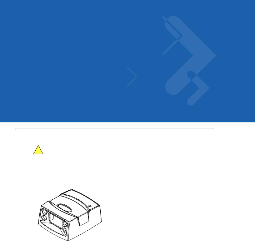
The Symbol MS440X fixed-mount imager is specifically designed for stand-alone applications, and OEM applications such as kiosks. The imager is extremely compact, provides easy and flexible integration of bar code imaging into a host device, and offers high-performance imaging on 1-D and 2-D bar codes. The Symbol MS440X is ideal for medical instruments and manufacturing applications.
Figure 1-1 Symbol MS440X MiniScan Imager
This integration guide includes parameters and describes the theory of operation, installation, specifications, and configuration.

1 - 2 Symbol MS4404/MS4407 Integration Guide
Symbol MS440X Features
•Stand-alone or OEM applications
•Quick and easy integration for OEM devices
•Excellent imaging performance on all 1-D and 2-D bar codes
•RS-232 (Serial) or USB Interface
•Direct part mark (DPM) support (DPM version only). Scan 2D symbols etched directly onto an item’s surface (via laser etching and dot peening) for permanent identification.
•Easy programming and configuration
•Flexible mounting options
•LEDs indicating power status and successful decodes.
Typical Applications
Fixed Mount Standalone Applications
•Clinical diagnostics
•Medical instruments
•Work stations
•Assembly lines. OEM Applications
•Kiosks / ATMs
•Music listening stations
•Medical instruments
•Clinical diagnostics
•Lottery terminals / gaming
•Airline gate check-in.
Theory of Operation
During image capture:
1.The imager sensor array contained in the SE4400 captures the image of the bar code through the optical system.
2.The PL4407 controls the SE4400 imager to obtain the best possible image quality.
3.The PL4407 transfers the decoded data or image data to the host system.
The result is a monochrome digital image similar to that of a digital camera. The output from the SE4400 is byte wide pixel data that is sent to the PL4407.
|
Getting Started |
1 - 3 |
|
|
|
|
|
|
|
|
|
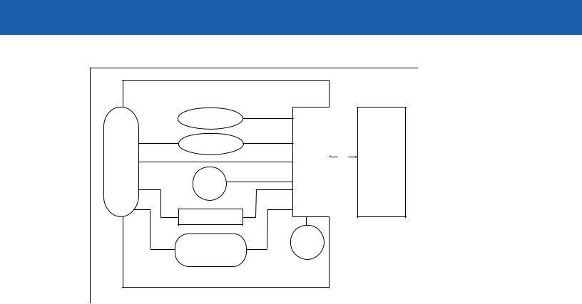
Block Diagrams
The MiniScan block diagrams illustrate the functional relationship of the MiniScan components. A detailed description of each component in the block diagrams is also provided.
Block Diagrams
|
Interface Board |
|
|
|
|
|
Voltage Regulator |
|
|
|
|
|
Beeper |
|
|
SE4400 |
|
|
|
PL4407 |
|
||
DB9 |
External Beeper |
flex |
(Imager) |
||
Decoder |
Data |
||||
|
|||||
|
|
|
|
||
|
|
|
|
Acquisition |
|
|
Interface Circuit |
|
|
Engine |
|
|
|
|
|
||
|
Red/ |
|
|
|
|
|
Green |
LED |
|
|
|
|
LED |
|
|
||
|
Illumina- |
|
|
||
|
|
|
|
||
|
|
tion |
|
|
|
|
External Trigger |
|
|
|
Figure 1-2 Symbol MS4404 Block Diagram
1 - 4 Symbol MS4404/MS4407 Integration Guide
.
|
Interface Board |
|
|
|
|
Beeper |
|
|
|
|
External Beeper |
PL4407 |
|
SE4400 |
DB9 |
|
flex |
(Imager) |
|
|
Decoder |
Data |
||
|
|
|||
|
Red/ |
|
|
Acquisition |
|
Green |
|
|
Engine |
|
LED |
|
|
|
|
External Trigger |
|
|
|
|
|
LED |
|
|
|
Interface Circuit |
Illumina- |
|
|
|
tion |
|
|
|
|
|
|
|
Figure 1-3 Symbol MS4407 Block Diagram
Miniscan Block Diagram Descriptions
Imager Engine - The SE4400 engine provides digital images which can be transmitted to a decoder to decode a bar code of any format supported by the decoding software. The engine utilizes laser aiming and an LED illumination system, and can switch between two focus positions for extended working range or for more precise focusing in high-density bar code decoding or digital picture taking.
Interface Board - The interface board adapts the imager engine's interface into usable signals and data for the host. It also contains a beeper. LED illumination and red/green LED for audio/visual feedback, and provides for an external trigger and external beeper.
The Symbol MS4404 interface board converts TTL level SSI signals to proper RS-232 levels for connection to any RS-232 compliant host, and the Symbol MS4407 interface board allows connection to logic level serial and USB hosts.
Voltage Regulator (Symbol MS4404 only) - The power supply allows the Symbol MS4404 to operate of the extended input voltages of 5 - 12 Vdc.
DB9 - The DB9 connector provides an outlet for the various interface signals used between a MiniScan and the host. It also maintains pin compatibility with MiniScan (MSXXXX) host cables.

Getting Started |
1 - 5 |
|
|
PL4407 Decoder
ARM9-Based Processor
The digital system is built on an ARM9 Harvard architecture core, 32 bit RISC engine with a five-stage pipeline. The major features of the core are:
•Programmable speed up to 150 MHz with an adjustable external bus speed up to 96 MHz.
•16K instruction and data cache (64-way set associative).
•Flexible internal bus architecture that supports DMA operations from any peripheral module to the core or to another peripheral port including main memory.
•Implementation of an enhanced Memory Management Unit (MMU).
Main Memory
The two available PL4407 microprocessor designs are:
•PL4407-x100: 32-bit external bus interface to 8 MB of PC100-compliant SDRAM, classified as Mobile SDRAM due to its lower operating current and enhanced power-down modes; internally configured as 4 banks of 512 kb x 32 bits.
•PL4407-x200: 32-bit external bus interface to 16 MB of Mobile SDRAM; internally configured as 4 banks of 1024 Kb x 32 bits.
Power Management (Symbol MS4404 Only)
NOTE This section does not apply to the USB interface. USB supports low power mode as defined by the USB specification.
The Symbol MS4404 has two power modes:
•Continuous Power
•Low Power.
In Continuous Power mode, the Symbol MS4404 system is always running even when not in a decode session.
In Low Power mode (the default power mode), the Symbol MS4404 draw less current than when in Continuous Power mode, and is more suitable for battery-powered applications. In this mode the Symbol MS4404 enter Low Power mode whenever possible. The Symbol MS4404 must be awakened from Low Power mode before performing any functions.

1 - 6 Symbol MS4404/MS4407 Integration Guide
Table 1-1 describes how to put the Symbol MS4404 into Low Power mode; Table 1-2 describes how to awaken it. Completely removing power from the Symbol MS4404 is not recommended; this should not be necessary as in Low Power mode the Symbol MS4404 consume very little power (see Table 1-1).
Table 1-1 Placing the Symbol MS4404 into Low Power Mode
Action |
Behavior |
|
|
Set the Power Mode parameter to Low |
The Symbol MS4404 enters Low Power mode |
Power (see Power Mode on page 6-8). |
automatically whenever possible. |
|
|
Send the serial SLEEP command |
The Symbol MS4404 enters Low Power mode only |
(see the Simple Serial Interface (SSI) |
once, as soon as possible. |
Programmer Guide). |
|
|
|
Note: All Wake Up signals (see Table 1-2) must be inactive to enter Low Power mode. Once the Symbol MS4404 is awakened, at least 1 second (programmable time) must elapse before it re-enters Low Power mode.
Table 1-2 Waking Up the Symbol MS4404
Signal |
State to Wake Up |
|
|
AIM/WKUP* |
Low |
|
|
TRIG* |
Low |
|
|
CTS* |
Low |
|
|
RXD |
Send 0x00 |
|
|
When the Symbol MS4404 is awakened, it remains awake for at least 1 second (programmable time) before re-entering Low Power mode; the host must perform its first action within this time period.
Serial I/O
Simple Serial Interface (SSI) Protocol is a half-duplex asynchronous serial interface with two hardware handshaking lines. The four SSI-specific interface signals are:
•TXD - Transmitted Data
•RXD - Received Data
•RTS* - Request to Send
•CTS* - Clear to Send
Signal names with the "*" modifier are asserted when at the positive logic 0 state (active low). Signal names without the "*" modifier are asserted when at the positive logic 1 state (active high).
The TXD line transmits asynchronous serial data from the Symbol MS440X to the host.
The RXD line is used by the Symbol MS440X to receive asynchronous serial data from the host. The SSI protocol does not support full-duplex data transfers; data is either transmitted or received by the Symbol MS440X, but never both simultaneously.
The RTS* and CTS* signals help coordinate data transfers between the Symbol MS440X and the host.

Chapter 2 Installation
Overview
This chapter provides information on unpacking, mounting, and installing the MiniScan imager.
Unpacking
Remove the MiniScan from its packing and inspect for damage. If the imager is damaged, call Motorola Enterprise Mobility Support on page xv.
KEEP THE PACKING. It is the approved shipping container and should be used if the equipment needs to be returned for servicing.
2 - 2 Symbol MS4404/MS4407 Integration Guide
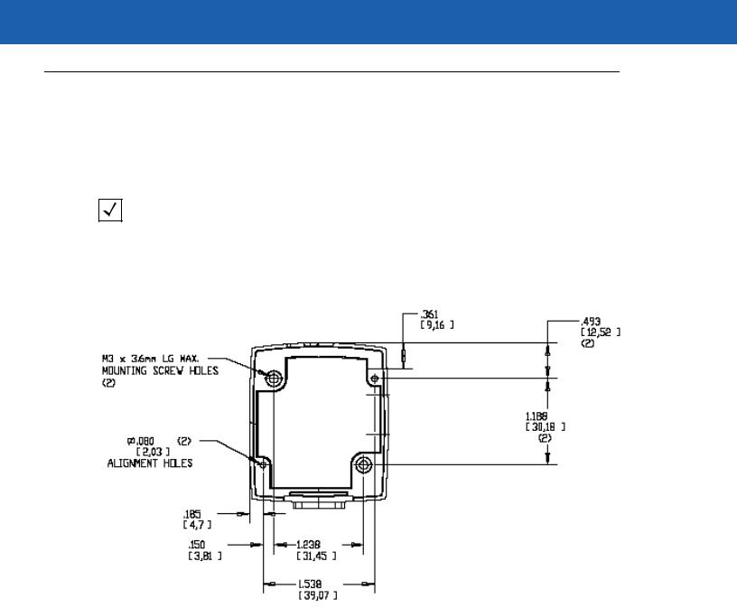
Mounting
There are two mounting holes (threaded inserts) on the bottom of the Symbol MS440X chassis.
The following figures provide mounting dimensions for the MiniScan housings. For a mounting template, see Chapter 13, Mounting Template.
NOTE Use only non-magnetic M3x.5 screws with a maximum length of 3.6mm to mount the MiniScan imager chassis.
Symbol MS440X Mounting Dimensions
Note: Dimensions are in inches [mm]
Exit Window
Figure 2-1 Symbol MS440X Mounting Dimensions

|
Getting Started |
2 - 3 |
|
|
|
|
|
|
|
|
|
Connecting the MiniScan
To connect the MiniScan to the host, connect the imager cables in the order shown in Figure 2-2.
To Host |
|
|
3 |
|
|
5 |
|
4 |
|
||
|
|
1
Trigger Jack (Optional) Trigger or Photo See Figure 2-3 Sensor (Optional)
2
Figure 2-2 Typical Connection Diagram
|
Male jack shown for reference |
|
1 |
Insertion |
1 |
|
Direction |
|
|
|
2 |
2
3
3
Note: Due to many variations of |
1 |
-1Ground- (Sleeve) |
jack and socket styles, identify |
2 |
-2Vcc- Battery(Middle(MiddleContact)Contact) |
terminals as shown before |
3 |
-3Trigger- (Tip) |
soldering leads.
Figure 2-3 Trigger Jack Connector Pins

2 - 4 Symbol MS4404/MS4407 Integration Guide
Location and Positioning
The location and positioning guidelines provided do not consider unique application characteristics. It is recommended that an opto-mechanical engineer perform an opto-mechanical analysis prior to integration.
NOTE Integrate the imager in an environment no more extreme than the product’s specification, where the imager will not exceed its temperature range. For instance, do not mount the imager onto or next to a large heat source. When placing the imager with another device, ensure there is proper convection or venting for heat. Follow these suggestions to ensure product longevity, warranty, and overall satisfaction with the imager.
Embedded Applications Requiring a Window
Use the following guidelines for applications that require a window in front of the MiniScan.
NOTE Motorola does not recommend placing an exit window in front of the MiniScan; however, the following information is provided for applications that require such a window.
Window Material
NOTE The window placement and material recommendations that follow should be considered if the Symbol MS440X is mounted within a product with its own window.
Many window materials that look perfectly clear can contain stresses and distortions that can reduce imager performance. For this reason, optical glass or cell-cast acrylic with an anti-reflection coating is highly recommended. Following is a description of acrylic, and CR-39, another popular window material. Table 2-1 outlines the suggested window properties.
|
CAUTION Consult an opto-mechanical engineer to recommend an appropriate window material and to |
determine if coatings are appropriate for the specific application. |
NOTE Do not use polycarbonate material.
Acrylic
When fabricated by cell-casting, acrylic has very good optical quality and low initial cost. However, protect the surface from the environment as acrylic is susceptible to attack by chemicals, mechanical stresses, and UV light. Acrylic has reasonably good impact resistance and can be ultrasonically welded.
CR-39
CR-39 is a thermal-setting plastic produced by the cell-casting process, and is commonly used in plastic eye glasses lenses. CR-39 has excellent chemical and environmental resistance, including good surface hardness. Typically it does not require hard-coating, but can be hard coated for severe environments. CR-39 has reasonably good impact resistance and cannot be ultrasonically welded.
Getting Started |
2 - 5 |
|
|
Chemically Tempered Float Glass
Glass is a hard material which provides excellent scratch and abrasion resistance. However, unannealed glass is brittle. Increasing flexibility strength with minimal optical distortion requires chemical tempering. Glass cannot be ultrasonically welded and is difficult to cut into odd shapes.
Table 2-1 Suggested Window Properties
Property |
Description |
|
|
Material |
Clear cell-cast acrylic. |
|
|
Spectral Transmission |
85% minimum from 640 to 690 nanometers. |
|
|
Thickness |
0.059 ± 0.005 |
|
|
Wavefront Distortion (transmission) |
0.2 wavelengths peak-to-valley maximum over any |
|
0.08 in. diameter within the clear aperture. |
|
|
Clear Aperture |
To extend to within 0.04 in. of the edges all around. |
|
|
Surface Quality |
60-20 scratch/dig |
|
|
Coating |
Both sides to be anti-reflection coated to provide |
|
0.5% max reflectivity (each side) from 640 to 690 |
|
nanometers at nominal window tilt angle. Coatings |
|
must comply with the hardness adherence |
|
requirements of MIL-M-13508. |
|
|
Window Coatings
Table 2-2 lists some exit window manufacturers and anti-reflection coaters.
Anti-Reflection Coatings
Apply an anti-reflection coating to the inside and/or outside of the window to significantly reduce the amount of light reflected off the window, back into the imager engine. The coating can also improve the range of acceptable window positions and minimize performance degradation due to signal loss as the light passes through the window. Using anti-reflection coatings on both the inside and outside of the window is highly recommended.

2 - 6 Symbol MS4404/MS4407 Integration Guide
Polysiloxane Coating
Polysiloxane type coatings are applied to plastic surfaces to improve the surface resistance to both scratch and abrasion. They are usually applied by dipping, then air-drying in an oven with filtered hot air.
Table 2-2 Window Manufacturers and Coaters
Company |
Discipline |
Specifics |
|
|
|
Evaporated Coatings, Inc. |
Anti-reflection coater |
Acrylic window supplier |
2365 Maryland Road |
|
Anti-reflection coater |
Willow Grove, PA 19090 |
|
|
(215) 659-3080 |
|
|
|
|
|
Fosta-Tek Optics, Inc. |
Cell-caster, hard coater, |
CR39 exit window |
320 Hamilton Street |
laser cutter |
manufacturer |
Leominster, MA 01453 |
|
|
(978) 534-6511 |
|
|
|
|
|
Glasflex Corporation |
Cell-caster |
Acrylic exit window |
4 Sterling Road |
|
manufacturer |
Sterling, NJ 07980 |
|
|
(908) 647-4100 |
|
|
|
|
|
Optical Polymers Int. (OPI) |
CR-39 cell-caster, coater, |
CR39 exit window |
110 West Main Street |
laser cutter |
manufacturer |
Milford, CT 06460 |
|
|
(203) 882-9093 |
|
|
|
|
|
Polycast |
acrylic cell-caster, hard |
Acrylic exit window |
70 Carlisle Place |
coater, laser cutter |
manufacturer |
Stamford, CT 06902 |
|
|
(800) 243-9002 |
|
|
|
|
|
TSP |
acrylic cell-caster, coater, |
Acrylic exit window |
2009 Glen Parkway |
laser cutter |
manufacturer |
Batavia, OH 45103 |
|
|
(800) 277-9778 |
|
|
|
|
|
Embedded Window Angle and Position
If a window is placed between the MiniScan and the item to be imaged, observe the following guidelines:
•Window Clear Opening - Make the clear opening of the window large enough so that the entire imager field of view passes through the window. Cutting off any part of the field of view can degrade decode range performance. Ensure that window placement relative to the MiniScan accounts for tolerances on all parts involved in that assembly.
•Window Angle - Angle the window at least 2o more than the tilt of the window on the imager (see Table 2-3). Further tilting the window is acceptable and decreases the possibility of a secondary reflection from that window degrading the imager's performance.
•Optical Working Range - Adding a window can reduce the working range of the imager since there is a signal loss when passing through window material. To minimize this reduction, use a special coating described in Window Coatings on page 2-5. To understand the difference, test the imager in the desired orientation and see if the difference affects imager performance.
 Loading...