


MC3000
User Guide
MC3000
User Guide
72E-68899-04
Revision A
September 2007

ii MC3000 User Guide
© 2007 by Motorola, Inc. All rights reserved.
No part of this publication may be reproduced or used in any form, or by any electrical or mechanical means, without permission in writing from Motorola. This includes electronic or mechanical means, such as photocopying, recording, or information storage and retrieval systems. The material in this manual is subject to change without notice.
The software is provided strictly on an “as is” basis. All software, including firmware, furnished to the user is on a licensed basis. Motorola grants to the user a non-transferable and non-exclusive license to use each software or firmware program delivered hereunder (licensed program). Except as noted below, such license may not be assigned, sublicensed, or otherwise transferred by the user without prior written consent of Motorola. No right to copy a licensed program in whole or in part is granted, except as permitted under copyright law. The user shall not modify, merge, or incorporate any form or portion of a licensed program with other program material, create a derivative work from a licensed program, or use a licensed program in a network without written permission from Motorola. The user agrees to maintain Motorola’s copyright notice on the licensed programs delivered hereunder, and to include the same on any authorized copies it makes, in whole or in part. The user agrees not to decompile, disassemble, decode, or reverse engineer any licensed program delivered to the user or any portion thereof.
Motorola reserves the right to make changes to any software or product to improve reliability, function, or design.
Motorola does not assume any product liability arising out of, or in connection with, the application or use of any product, circuit, or application described herein.
No license is granted, either expressly or by implication, estoppel, or otherwise under any Motorola, Inc., intellectual property rights. An implied license only exists for equipment, circuits, and subsystems contained in Motorola products.
MOTOROLA and the Stylized M Logo and Symbol and the Symbol logo are registered in the US Patent & Trademark Office. All other product or service names are the property of their respective owners. Bluetooth is a registered trademark of Bluetooth SIG. Microsoft, Windows and ActiveSync are either registered trademarks or trademarks of Microsoft Corporation. Other product names mentioned in this manual may be trademarks or registered trademarks of their respective companies and are hereby acknowledged.
Motorola, Inc.
One Motorola Plaza
Holtsville, New York 11742-1300, USA
http://www.symbol.com
Patents
This product is covered by one or more of the patents listed on the website: www.symbol.com/patents

iii
Revision History
Changes to the original manual are listed below:
Change |
Date |
Description |
|
|
|
-01 Rev A |
Dec. 2004 |
Initial Release |
|
|
|
-01 Rev B |
June 2005 |
Added Four Slot Ethernet cradle. |
|
|
|
|
|
Appendix A, added Accessory Specifications. |
|
|
|
-02 Rev A |
November 2005 |
Chapter 7, removed WZC, replaced with wireless application description. |
|
|
Global changes: |
|
|
Changed Windows CE.NET 4.2 to Windows CE.NET 5.0 |
|
|
Removed WZC references, replaced with wireless application references. |
|
|
Added 802.11a. |
|
|
Page 2-9 and 2-10 added Four Slot Ethernet cradle. |
|
|
|
-02 Rev B |
June 2006 |
Add Direct Part Marking information, MC3090S 128 MB RAM/64 MB Flash |
|
|
configuration and update SMDK information. |
|
|
|
-03 Rev A |
Jan 2007 |
Add 20-key mechanical keypad, Fusion 2.5, BT Profile application. |
|
|
|
-04 Rev A |
August 2007 |
Motorola re-branding, operating system update: OEM version 05.26.0000. |
|
|
|

iv MC3000 User Guide

Table of Contents
Patents.................................................................................................................................................. |
ii |
Revision History.................................................................................................................................... |
iii |
About This Guide |
|
Introduction ........................................................................................................................................... |
xi |
Documentation Set ......................................................................................................................... |
xi |
Configurations....................................................................................................................................... |
xii |
Software Versions........................................................................................................................... |
xiii |
Chapter Descriptions ............................................................................................................................ |
xiv |
Notational Conventions......................................................................................................................... |
xiv |
Related Documents and Software ........................................................................................................ |
xv |
Service Information............................................................................................................................... |
xv |
Chapter 1: Getting Started |
|
Introduction .......................................................................................................................................... |
1-1 |
Unpacking the Mobile Computer ......................................................................................................... |
1-1 |
Accessories ......................................................................................................................................... |
1-2 |
Parts .................................................................................................................................................... |
1-3 |
Rotating Scan Turret ...................................................................................................................... |
1-4 |
Mobile Computer Startup ..................................................................................................................... |
1-5 |
Install Main Battery ........................................................................................................................ |
1-5 |
Battery Charging .................................................................................................................................. |
1-7 |
Spare Battery Charging ....................................................................................................................... |
1-9 |
Stylus ................................................................................................................................................... |
1-9 |
Starting the Mobile Computer .............................................................................................................. |
1-9 |
Calibration Screen ......................................................................................................................... |
1-10 |
Waking the Mobile Computer .............................................................................................................. |
1-11 |
Main Battery Removal ......................................................................................................................... |
1-11 |
Strap/Door Assembly Removal and Replacement (MC3000S/R) ....................................................... |
1-12 |
Strap/Door Assembly Removal and Replacement (MC3090G) ........................................................... |
1-13 |
Turning Off the Radios ......................................................................................................................... |
1-14 |
On Device with CE 5.0 (OEM Version 01.15 or lower) .................................................................. |
1-14 |
WLAN Radio ............................................................................................................................ |
1-14 |

vi MC3000 User Guide
Bluetooth Radio ....................................................................................................................... |
1-15 |
On Device with CE 5.0 (OEM Version 01.16 or higher) ................................................................. |
1-15 |
WLAN Radio ............................................................................................................................ |
1-15 |
Bluetooth Radio ....................................................................................................................... |
1-15 |
Chapter 2: Operating the MC3000 |
|
Introduction .......................................................................................................................................... |
2-1 |
Power Button ....................................................................................................................................... |
2-1 |
Keypads ............................................................................................................................................... |
2-1 |
Keypad Special Functions ................................................................................................................... |
2-2 |
20-Key Mechanical Keypad ........................................................................................................... |
2-3 |
28-Key Keypad .............................................................................................................................. |
2-5 |
38-Key Keypad .............................................................................................................................. |
2-8 |
48-Key Keypad .............................................................................................................................. |
2-11 |
Demo Window ..................................................................................................................................... |
2-13 |
Desktop Window .................................................................................................................................. |
2-13 |
Taskbar ................................................................................................................................................ |
2-14 |
Battery Unknown Icon .................................................................................................................... |
2-15 |
Start Button .................................................................................................................................... |
2-15 |
Programs Menu ............................................................................................................................. |
2-16 |
Keyboard Input Panel Button ......................................................................................................... |
2-16 |
Desktop Display Button .................................................................................................................. |
2-16 |
Task Manager and Properties ............................................................................................................. |
2-17 |
Task Manager ................................................................................................................................ |
2-17 |
Properties ....................................................................................................................................... |
2-18 |
Entering Information ............................................................................................................................ |
2-19 |
Entering Information Using Keypad ............................................................................................... |
2-19 |
Entering Information Using the Keyboard Input Panel ................................................................... |
2-19 |
Entering Data via the Bar Code Scanner ....................................................................................... |
2-19 |
Data Capture ....................................................................................................................................... |
2-20 |
Laser Scanning .............................................................................................................................. |
2-20 |
Scan LED Indicators ...................................................................................................................... |
2-20 |
Scanning Considerations ............................................................................................................... |
2-20 |
Laser Decode Ranges ................................................................................................................... |
2-21 |
Imaging ................................................................................................................................................ |
2-23 |
Imager ............................................................................................................................................ |
2-23 |
Operational Modes ................................................................................................................... |
2-23 |
Aiming the Mobile Computer .......................................................................................................... |
2-24 |
Imager Decode Ranges ................................................................................................................. |
2-25 |
Direct Part Marking ........................................................................................................................ |
2-27 |
Resetting the Mobile Computer ........................................................................................................... |
2-28 |
Performing a Warm Boot ............................................................................................................... |
2-28 |
Performing a Cold Boot .................................................................................................................. |
2-28 |
Waking the Mobile Computer .............................................................................................................. |
2-29 |
File System Directory Structure ........................................................................................................... |
2-29 |
Connecting to the Internet on a Wireless LAN Network ...................................................................... |
2-30 |
Table of Contents |
vii |
|
|
Chapter 3: Using Bluetooth |
|
Introduction .......................................................................................................................................... |
3-1 |
Security ................................................................................................................................................ |
3-2 |
Turning the Bluetooth Radio Mode On and Off ................................................................................... |
3-2 |
Disabling Bluetooth ........................................................................................................................ |
3-2 |
Enabling Bluetooth ......................................................................................................................... |
3-3 |
Bluetooth Power States ................................................................................................................. |
3-3 |
Cold Boot ................................................................................................................................. |
3-3 |
Warm Boot ............................................................................................................................... |
3-3 |
Suspend ................................................................................................................................... |
3-4 |
Resume .................................................................................................................................... |
3-4 |
Bluetooth Profiles ................................................................................................................................. |
3-4 |
Modes .................................................................................................................................................. |
3-5 |
Wizard Mode .................................................................................................................................. |
3-5 |
Explorer Mode ................................................................................................................................ |
3-7 |
Discovering Bluetooth Device(s) .......................................................................................................... |
3-8 |
Bonding with Discovered Device(s) ......................................................................................... |
3-9 |
Renaming a Bonded Device .................................................................................................... |
3-11 |
Deleting a Bonded Device ....................................................................................................... |
3-11 |
Accepting a Bond ..................................................................................................................... |
3-12 |
File Transfer Services .................................................................................................................... |
3-14 |
Create New File or Folder ........................................................................................................ |
3-14 |
Delete File ................................................................................................................................ |
3-15 |
Get File .................................................................................................................................... |
3-15 |
Put File ..................................................................................................................................... |
3-15 |
Connect to Internet Using Access Point ........................................................................................ |
3-15 |
Dial-Up Networking Services ......................................................................................................... |
3-15 |
Add a Dial-up Entry .................................................................................................................. |
3-17 |
OBEX Object Push Services .......................................................................................................... |
3-18 |
Send a Picture ......................................................................................................................... |
3-18 |
Headset Services ........................................................................................................................... |
3-19 |
Serial Port Services ....................................................................................................................... |
3-20 |
Personal Area Network Services ................................................................................................... |
3-21 |
Bluetooth Settings ................................................................................................................................ |
3-21 |
Device Info Tab .............................................................................................................................. |
3-21 |
Services Tab .................................................................................................................................. |
3-22 |
Dial-Up Networking Service ..................................................................................................... |
3-22 |
File Transfer Service ................................................................................................................ |
3-23 |
OBEX Object Push Service ..................................................................................................... |
3-24 |
Personal Area Networking Service .......................................................................................... |
3-24 |
Serial Port Service ................................................................................................................... |
3-25 |
Headset Service ....................................................................................................................... |
3-25 |
Security Tab ................................................................................................................................... |
3-26 |
Discovery Tab ................................................................................................................................ |
3-26 |
Virtual COM Port Tab ..................................................................................................................... |
3-27 |
Miscellaneous Tab ......................................................................................................................... |
3-28 |
Chapter 4: Accessories |
|
Introduction .......................................................................................................................................... |
4-1 |

viii MC3000 User Guide
Cradles ........................................................................................................................................... |
4-1 |
Spare Battery Chargers ................................................................................................................. |
4-1 |
Cables ............................................................................................................................................ |
4-1 |
SD Card ......................................................................................................................................... |
4-2 |
Plastic Holster ................................................................................................................................ |
4-2 |
Fabric Holster ................................................................................................................................. |
4-2 |
Single Slot Serial/USB Cradle ............................................................................................................. |
4-2 |
Battery Charging ............................................................................................................................ |
4-2 |
LED Charge Indications ........................................................................................................... |
4-3 |
Four Slot Cradles ................................................................................................................................. |
4-5 |
Battery Charging ............................................................................................................................ |
4-5 |
LED Charge Indications ................................................................................................................. |
4-6 |
Power LED ..................................................................................................................................... |
4-6 |
Speed LED ..................................................................................................................................... |
4-6 |
Link LED ........................................................................................................................................ |
4-6 |
Four Slot Spare Battery Charger ......................................................................................................... |
4-7 |
Spare Battery Charging ................................................................................................................. |
4-7 |
LED Charge Indications ................................................................................................................. |
4-8 |
Cables .................................................................................................................................................. |
4-8 |
Battery Charging and Operating Power ......................................................................................... |
4-9 |
LED Charge Indications ................................................................................................................. |
4-9 |
Universal Battery Charger (UBC) Adapter ........................................................................................... |
4-10 |
Spare Battery Charging ................................................................................................................. |
4-10 |
UBC Adapter LED Charge Indications ........................................................................................... |
4-10 |
Secure Device Card ............................................................................................................................. |
4-12 |
Plastic Holster ...................................................................................................................................... |
4-13 |
Fabric Holster ...................................................................................................................................... |
4-15 |
Belt Clip .................................................................................................................................... |
4-15 |
Shoulder Strap ......................................................................................................................... |
4-16 |
Chapter 5: Maintenance and Troubleshooting |
|
Introduction .......................................................................................................................................... |
5-1 |
Maintaining the Mobile Computer ........................................................................................................ |
5-1 |
Battery Safety Guidelines .................................................................................................................... |
5-1 |
Troubleshooting ................................................................................................................................... |
5-2 |
Mobile Computer ............................................................................................................................ |
5-2 |
Single Slot Serial/USB Cradle ........................................................................................................ |
5-4 |
Four Slot Charge Only Cradle ........................................................................................................ |
5-5 |
Four Slot Ethernet Cradle .............................................................................................................. |
5-6 |
Four Slot Spare Battery Charger ................................................................................................... |
5-6 |
UBC Adapter .................................................................................................................................. |
5-7 |
Cables ............................................................................................................................................ |
5-8 |
Appendix A: Technical Specifications |
|
Mobile Computer And Accessory Technical Specifications ................................................................. |
A-1 |
Table of Contents |
ix |
|
|
Appendix B: Keypad Functions/Special Characters |
|
Introduction .......................................................................................................................................... |
B-1 |
Keypads ............................................................................................................................................... |
B-1 |
Appendix C: Regulatory |
|
Introduction .......................................................................................................................................... |
C-1 |
Accessory Power Supply Regulatory Compliance ............................................................................... |
C-1 |
Glossary
Index

x MC3000 User Guide

About This Guide
Introduction
This guide provides information about using the MC3000 mobile computers and accessories.
NOTE Screens and windows pictured in this guide are samples and may differ from actual screens.
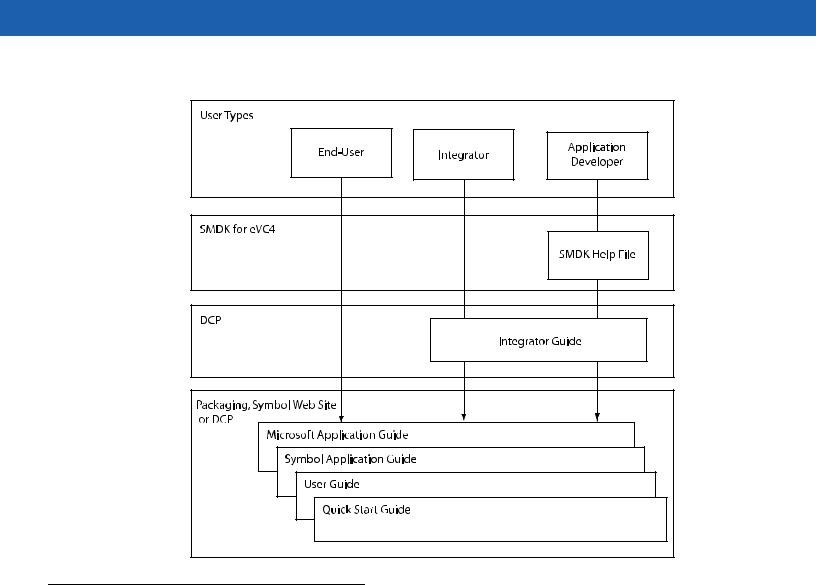
Documentation Set
The documentation set for the MC3000 is divided into guides that provide information for specific user needs.
•Microsoft Application Guide - describes how to use Microsoft developed applications.
•Symbol Application Guide - describes how to use Symbol developed applications.
•MC3000 User Guide - describes how to use the MC3000 mobile computer.
•MC3000 Integrator Guide - describes how to set up the MC3000 mobile computer and the accessories.
•SMDK Help File - provides API information for writing applications.
xii MC3000 User Guide
Configurations
This guide covers the following configurations:
Configuration |
Radios |
Display |
Memory |
Data |
Operating |
Keypads |
|
Capture |
System |
||||||
|
|
|
|
|
|||
|
|
|
|
|
|
|
|
MC3000R |
None |
Color or |
32 MB RAM/ |
1D laser |
Windows |
28, 38 or 48 |
|
|
|
monochrome |
64 MB Flash or |
scanner in |
CE 5.0 Core or |
key |
|
|
|
|
64 MB RAM/ |
rotating |
Professional |
|
|
|
|
|
64 MB Flash |
turret |
|
|
|
|
|
|
|
|
|
|
|
MC3090G |
WLAN: 802.11a/b/g |
Color or |
32 MB RAM/ |
1D laser |
Windows |
28, 38 or 48 |
|
|
WPAN: Bluetooth |
monochrome |
64 MB Flash or |
scanner or |
CE 5.0 Core or |
key |
|
|
|
|
64 MB RAM/ |
2D imager |
Professional |
|
|
|
|
|
64 MB Flash |
|
|
|
|
|
|
|
|
|
|
|
|
MC3090S |
WLAN: 802.11a/b/g |
Color |
64 MB RAM/ |
2D imager or |
Windows |
28, 38, 48 key |
|
|
WPAN: Bluetooth |
|
64 MB Flash or |
DPM Imager |
CE 5.0 |
or 20 key |
|
|
|
|
128 MB RAM/ |
|
Professional |
Mechanical |
|
|
|
|
64 MB Flash |
|
|
|
|
|
|
|
|
|
|
|
|
MC3090R |
WLAN: 802.11a/b/g |
Color or |
32 MB RAM/ |
1D laser |
Windows |
28, 38, 48 key |
|
|
WPAN: Bluetooth |
monochrome |
64 MB Flash |
scanner in |
CE 5.0 Core or |
or 20 key |
|
|
|
|
|
rotating |
Professional |
Mechanical |
|
|
|
|
|
turret |
|
|
|
|
|
|
|
|
|
|
About This Guide |
xiii |
|
|
Software Versions
This guide covers various software configurations and references are made to operating system or software versions for:
•OEM version
•Fusion version.
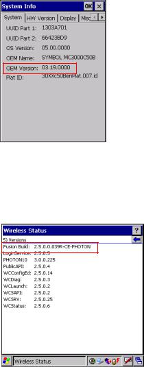
OEM Software
To determine the OEM software version:
Tap Start > Settings > Control Panel > System Information icon > System tab.
Fusion Software
To determine the Fusion software version:
Tap Wireless Strength icon > Wireless Status > Versions.

xiv MC3000 User Guide
Chapter Descriptions
Topics covered in this guide are as follows:
•Chapter 1, Getting Started, describes the mobile computer’s physical characteristics, how to install and charge the batteries, remove and replace the Strap/Door assembly and how to start the mobile computer for the first time.
•Chapter 2, Operating the MC3000, provides basic instructions for using the mobile computer and navigating the mobile computer software.
•Chapter 3, Using Bluetooth, explains how to perform Bluetooth functionality on the mobile computer.
•Chapter 4, Accessories, describes the accessories available for the mobile computer and how to use the accessories to charge the mobile computer.
•Chapter 5, Maintenance and Troubleshooting, includes instructions on cleaning and storing the mobile computer, and provides troubleshooting solutions for potential problems during mobile computer operation.
•Appendix A, Technical Specifications, includes a table listing the technical specifications for the mobile computer.
•Appendix B, Keypad Functions/Special Characters, contains special character generation tables.
Notational Conventions
The following conventions are used in this document:
•The term “mobile computer” refers to the Symbol MC3000.
•Italics are used to highlight the following:
•Chapters and sections in this and related documents
•Dialog box, window and screen names
•Drop-down list and list box names
•Check box and radio button names
•Icons on a screen.
•Bold text is used to highlight the following:
•Key names on a keypad
•Button names on a screen.
•Bullets (•) indicate:
•Action items
•Lists of alternatives
•Lists of required steps that are not necessarily sequential.
•Sequential lists (e.g., those that describe step-by-step procedures) appear as numbered lists.

About This Guide |
xv |
|
|
Related Documents and Software
The following items provide more information about the MC3000 mobile computers.
•MC3000 Series Quick Start Guide, p/n 72-68902-xx
•MC3090G Quick Start Guide, p/n 72-71347-xx
•MC3000 Licensing, Patent and Regulatory Information, p/n 72-68903-xx
•MC3000 Integrator Guide, p/n 72E-68900-xx
•Symbol Application Guide for Symbol Devices, p/n 72E-68901-xx
•Microsoft® Applications for Mobile and CE 5.0 User Guide, p/n 72E-78456-xx
•Symbol Mobility Developer Kit (SMDK) Help File, p/n 72E-38880-03
•Windows CE Platform SDK for MC3000c50, available at: http://support.symbol.com
•Symbol Mobility Developer Kit for C (SMDK for C), available at: http://support.symbol.com
•Device Configuration Package for MC3000 (DCP for MC3000), available at: http://support.symbol.com
•ActiveSync software, available at: http://www.microsoft.com.
For the latest version of this guide and all guides, go to: http://support.symbol.com.
Service Information
If you have a problem with your equipment, contact Motorola Enterprise Mobility support for your region. Contact information is available at: http://www.symbol.com/contactsupport.
When contacting Enterprise Mobility support, please have the following information available:
•Serial number of the unit
•Model number or product name
•Software type and version number
Motorola responds to calls by email, telephone or fax within the time limits set forth in support agreements.
If your problem cannot be solved by Motorola Enterprise Mobility Support, you may need to return your equipment for servicing and will be given specific directions. Motorola is not responsible for any damages incurred during shipment if the approved shipping container is not used. Shipping the units improperly can possibly void the warranty.
If you purchased your Enterprise Mobility business product from a Motorola business partner, contact that business partner for support.

xvi MC3000 User Guide

Chapter 1 Getting Started
Introduction
This chapter describes the mobile computer physical characteristics, how to install and charge the batteries, how to remove and replace the Strap/Door Assembly and how to start the mobile computer for the first time.
Unpacking the Mobile Computer
Carefully remove all protective material from around the mobile computer and save the shipping container for later storage and shipping. Verify that the equipment listed below is included:
•MC3000 mobile computer
•Strap/Door Assembly, attached to the mobile computer
•Stylus
•Regulatory Guide
•Quick Start Guide.
Depending on the configuration ordered, the mobile computer shipping container or additional shipping container may include:
•Standard battery (lithium-polymer)
•Extended life battery (lithium-ion)
•Cable(s)
•Power supply
•Cradles.
Inspect the equipment for damage. If any equipment is missing or damaged, contact the Motorola Enterprise Mobility Support immediately. See Service Information on page xv for contact information.

1 - 2 MC3000 User Guide
Accessories
Table 1-1 lists the MC3000 accessories.
Table 1-1 MC3000 Accessories
Accessory |
Description |
|
|
Single Slot Serial/USB Cradle |
Charges the mobile computer main battery and a spare battery, and |
|
synchronizes the mobile computer with a host computer through either a serial |
|
or USB connection. |
|
|
Four Slot Charge Only Cradle |
Charges up to four mobile computers. |
|
|
Four Slot Ethernet Cradle |
Charges up to four mobile computers and provides Ethernet communications. |
|
|
Four Slot Spare Battery Charger |
Charges up to four mobile computer spare batteries. |
|
|
Power Supply |
Country specific and accessory specific, power supply. |
|
|
USB Client Charge Cable |
Provides USB client communication capabilities and charges the mobile |
|
computer. |
|
|
RS232 Charge Cable |
Provides RS232 communication capabilities and charges the mobile |
|
computer. |
|
|
O’Neil Printer Cable |
Provides printer specific communication capabilities (provided by O’Neil). |
|
|
Zebra Printer Cable |
Provides printer specific communication capabilities (provided by Zebra). |
|
|
Monarch Printer Cable |
Provides printer specific communication capabilities (provided by Monarch). |
|
|
Single Slot Cradle RS232 Cable |
Provides serial host communication capabilities and charges the mobile |
|
computer. |
|
|
Single Slot Cradle USB Cable |
Provides USB communication capabilities and charges the mobile computer. |
|
|
MC3000 Universal Battery Charger |
Adapts the UBC for use with MC3000 batteries. |
Adapter (UBC) |
|
|
|
Stylus |
Performs pen and mouse functions. |
|
|
Plastic Holster |
Provides a clip on holder for the mobile computer. |
|
|
Fabric Holster |
Provides a soft, clip on holder and a shoulder strap for the mobile computer. |
|
|
Symbol Mobility Developer Kit for |
A development tool used to create native C and C++ applications for all |
C (SMDK for C) |
Symbol mobile computers running the Microsoft Windows CE operating |
|
system. Available at: http://support.symbol.com. |
|
|
Device Configuration Package |
A development tool used to create and download hex images that represent |
(DCP) for MC3000 |
flash partitions to the mobile computer. Available at: |
|
http://support.symbol.com. |
|
|
Getting Started |
1 - 3 |
|
|
Parts
There are three versions of the MC3000 mobile computers, the MC3000 1D/2D Imager (MC3000S or MC3090S), the MC3000 Laser with Rotating Scan Turret (MC3000R or MC3090R) and the MC3090 Gun (MC3090G). For more information on the Rotating Scan Turret, see Figure 1-3 on page 1-4.
Rotating Scan |
Scan LED Indicator |
|||
Turret |
(red/green) |
|||
Scan LED |
|
|||
Indicators |
Beeper or |
|||
(red/green) |
||||
Receiver |
||||
|
|
|
||
|
|
|
(optional) |
|
|
|
|
Display |
|
|
|
|
Indicator LED Bar |
|
Charge LED |
|
|||
Indicator |
|
|||
(amber) |
Scan Buttons |
|||
|
|
|
||
Keypad |
|
|||
|
|
|
|
|
|
|
|
|
|
Microphone
(optional)
Power
MC3000R MC3000S
Figure 1-1 MC3000 Imager and MC3000 Laser Mobile Computers (Front View)
1 - 4 MC3000 User Guide
|
Headset Jack |
|
Scan Window |
(optional) |
Scan Window |
Headset Jack |
Strap/Door |
(optional) |
Assembly |
|
Screws |
 Stylus
Strap/Door
Assembly
Stylus
Holder
Latches
MC3000S |
MC3000R |
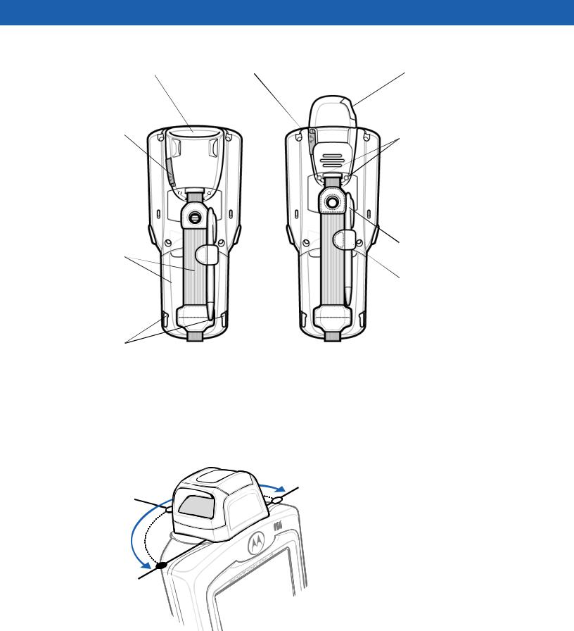
Figure 1-2 MC3000 Imager and MC3000 Laser Mobile Computers (Back View)
Rotating Scan Turret
The MC3000R mobile computer features a Rotating Scan Turret with three position stops. This feature offers greater scanning flexibility.
Position Stop
Position Stop
Position Stop
Figure 1-3 Rotating Scan Turret
Getting Started |
1 - 5 |
|
|
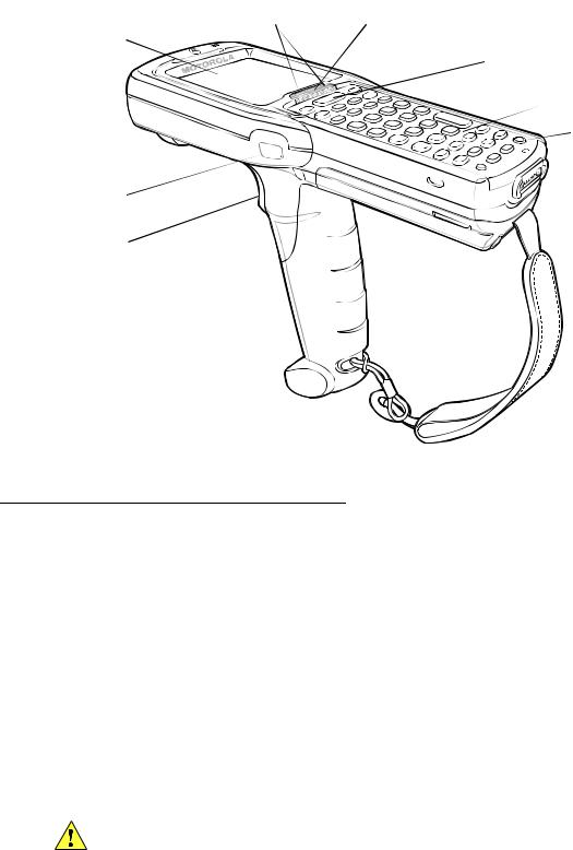
Beeper |
Scan LED |
Charge LED |
|
Indicators |
Indicator |
|
|
|
|
||
|
(red/green) |
(amber) |
Indicator LED Bar |
Display
 Scan Button
 Keypad
 Power
Power
Scan LED Indicator  (red/green)
Trigger
Figure 1-4 MC3090G Mobile Computer
Mobile Computer Startup
To start using the mobile computer:
•Install the main battery.
•Charge the main battery and the backup battery.
•Start the mobile computer.
Install Main Battery
If the main battery is charged, the mobile computer can be used immediately. If the main battery is not charged, see Battery Charging on page 1-7. To remove the main battery, see Main Battery Removal on page 1-11.
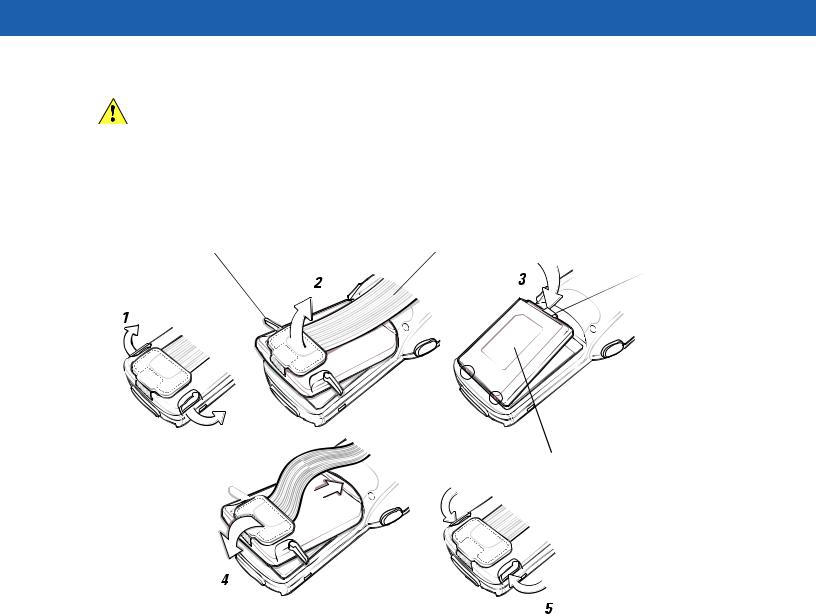
To install the main battery:
1.Rotate the latches to the open position.
CAUTION Do not lift up on the latches when removing the Strap/Door Assembly. Lift up on the Hand Strap only.
2.Pull on the strap to lift the Strap/Door Assembly off, bottom first.
1 - 6 MC3000 User Guide
CAUTION On the MC3090G battery, do not remove the battery pull tab. The pull tab is for enabling easy battery removal from the device.
3.Insert the battery into the slot, bottom first and press the battery gently into the slot. The battery clip locks the battery into place.
4.With the latches in the open position, replace the Strap/Door Assembly, top first and press to close.
5.Rotate the latches (to the lock position) to lock the Strap/Door Assembly in place.
Latches |
Hand Strap |
Battery Clip
Battery Slot
Battery
Strap/Door
Assembly


Figure 1-5 Main Battery Installation (MC3000S/R)
Getting Started |
1 - 7 |
|
|
Latches |
Hand Strap |
|
|
|
|
1 |
2 |
3 |
|||
|
|
|
|
|
|
|
|
|
|
|
|
|
|
|
|
|
|
|
|
|
|
|
|
0.5 in. 
(12.7 mm) 
Strap/Door
Assembly
Battery
5
Strap/Door
 Assembly
Figure 1-6 Main Battery Installation (MC3090G)
Battery Charging
CAUTION Ensure that you follow the guidelines for battery safety described in Battery Safety Guidelines on page 7-1.
Use the mobile computer cradles, cables and spare battery chargers to charge the mobile computer main battery.
The main battery can be charged before insertion into the mobile computer or after it is installed. There are two main batteries for the MC3000, the Standard Battery and the Extended Life Battery. Either battery can be used, but the Extended Life Battery requires a different Strap/Door Assembly. Use one of the spare battery chargers to charge the main battery (out of the mobile computer) or one of the cradles to charge the main battery while it is installed in the mobile computer.
Before using the mobile computer for the first time, fully charge the main battery until the amber Charge LED Indicator remains lit (see Table 1-2 on page 1-8 for charge status indications). The Standard Battery fully charges in less than four hours and the Extended Life Battery fully charges in less than six hours.
The mobile computer is equipped with a memory backup battery which automatically charges from the main battery whether or not the mobile computer is operating or is in suspend mode. The memory backup battery retains data in memory for at least 30 minutes when the mobile computer’s main battery is removed or fully discharged. When the mobile computer is used for the first time or after the memory backup battery has fully discharged, the memory backup battery requires approximately 15 hours to fully charge. Do not remove the main battery from the mobile computer for 15 hours to ensure that the memory backup battery fully charges. If the main battery is

1 - 8 MC3000 User Guide
removed from the mobile computer or the main battery is fully discharged, the memory backup battery completely discharges in several hours.
When the main battery reaches a very low battery state, the combination of main battery and backup battery retains data in memory for at least 72 hours.
NOTE Do not remove the main battery within the first 15 hours of use. If the main battery is removed before the backup battery is fully charged, data may be lost.
Batteries must be charged within the 32° to 104° F (0° to +40° C) ambient temperature range.
The following accessories can be used to charge batteries:
•Cradles (and a power supply):
•Single Slot Serial/USB Cradle
•Four Slot Cradles.
•Cables (and a power supply):
•USB Client Charge Cable
•Serial (RS232) Charge Cable.
•Spare Battery Chargers (and a power supply):
•Single Slot Serial/USB Cradle
•Four Slot Spare Battery Charger
•Universal Battery Charger (UBC) Adapter.
To charge the mobile computer using the cradles:
1.Insert the mobile computer into a cradle. See Chapter 4, Accessories for accessory setup.
2.The mobile computer starts to charge automatically. The amber Charge LED Indicator indicates the charge status. See Table 1-2 on page 1-8 for charging indications.
To charge the mobile computer using the cables:
1.Connect the MC3000 Communication/Charge Cable to the appropriate power source and connect to the mobile computer. See Chapter 4, Accessories for accessory setup.
2.The mobile computer starts to charge automatically. The amber Charge LED Indicator indicates the charge status. See Table 1-2 for charging indications.
Table 1-2 Mobile Computer LED Charge Indicators
LED |
Indication |
|
|
Off |
Mobile computer not placed correctly in the cradle; charge cable not connected correctly; |
|
charger is not powered. |
|
|
Fast Blinking Amber |
Error in charging; check placement of the mobile computer. |
|
|
Slow Blinking Amber |
Mobile computer is charging. |
|
|
Solid Amber |
Charging complete. |
|
Note: When the battery is initially inserted in the mobile computer, the amber LED |
|
flashes once if the battery power is low or the battery is not fully inserted. |
|
|

Getting Started |
1 - 9 |
|
|
Spare Battery Charging
There are three accessories that can be used to charge a spare battery:
•Single Slot Serial/USB Cradle
•Four Slot Spare Battery Charger
•UBC Adapter.
To charge a spare battery:
1.Connect the charging accessory to the appropriate power source. See Chapter 4, Accessories for setup instructions.
2.Insert the spare battery into the spare battery charging slot and gently press down on the battery to ensure proper contact.
The battery starts to charge automatically. The amber charge LED Indicator lights to indicate the charge status. See Chapter 4, Accessories for charging indications. The Standard Battery usually fully charges in less than four hours and the Extended Life Battery usually fully charges in less than six hours.
Stylus
Use the stylus for selecting items and entering information on the screen. The stylus functions as a pen and a mouse. Tap the touch screen once with the stylus to select options and open menu items.
To remove the stylus, slide the stylus out of the stylus holder. To store the stylus, push the stylus back into the stylus holder.
Starting the Mobile Computer
On 28, 38 and 48-key keypad configurations, press the Power button to turn on the mobile computer. On 20-key keypad configurations, simultaneously press the Fn and MENU buttons to turn on the mobile computer. If the mobile computer does not power on, perform a cold boot. See Resetting the Mobile Computer on page 2-28.
When the mobile computer is powered on for the first time, it initializes. The Splash screen appears for a short period of time, followed by the Calibration screen.
OR
Figure 1-7 Splash Screen
1 - 10 MC3000 User Guide
After the calibration procedure is performed the factory settings launch the Demo window. Application specific shells may provide application specific windows instead of the Demo window. These screens also appear when a cold boot is performed.
If the mobile computer does not power on, see Resetting the Mobile Computer on page 2-28.
Calibration Screen
Use the Calibration screen to align the touch screen:
1.Remove the stylus from the stylus holder.
2.Carefully press and briefly hold the stylus tip on the center of the Calibration screen target. Repeat the procedure as the target moves and stops at different locations on the screen. This enters the new calibration settings.
|
|
|
Calibration Screen |
|
Confirm Calibration |
|
|
Resave Screen |
Figure 1-8 Calibration Screen
3.Once all of the new calibration settings are input, tap the screen or press the ENTER button to save the new calibration settings. Press ESC to discard the new calibration settings.
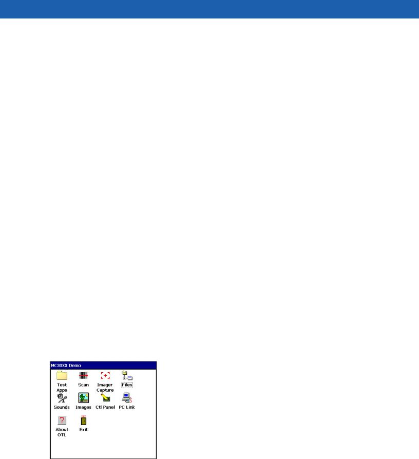
Demo Window
The Demo window is the factory default menu. On initial power up (or on a warm or cold boot) the Demo window appears. These sample/demo applications are intended to be used by application developers as application development examples. These applications were not developed to support end users. Refer to the Symbol Application Guide for information about the Demo window applications.
Figure 1-9 Demo Window
Getting Started 1 - 11
Waking the Mobile Computer
The wakeup condition settings are used to define what actions wake up the mobile computer. The settings are configurable so they are subject to change/update. For more information see, Waking the Mobile Computer on page 2-29.
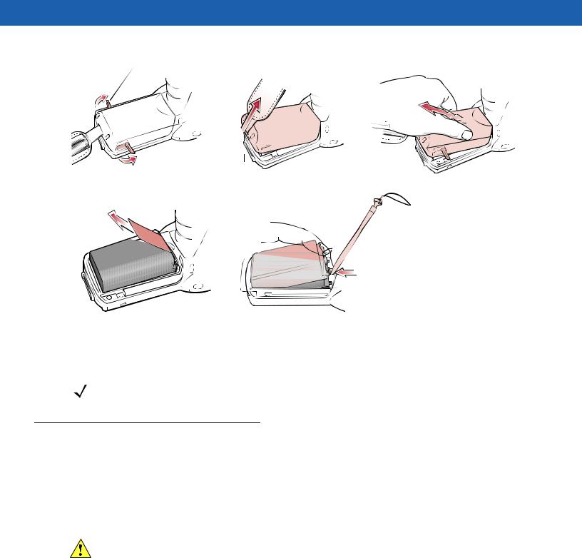
Main Battery Removal
Before removing the main battery, turn off the mobile computer.
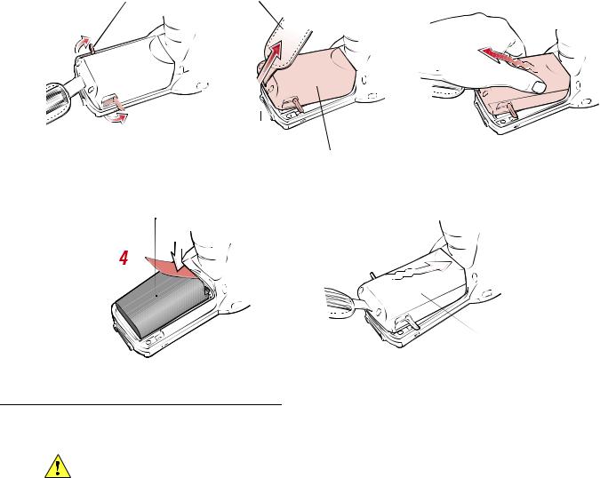
To remove the main battery:
1.Rotate the latches to the open position.
CAUTION Do not lift up on the latches when removing the Strap/Door Assembly. Lift up on the Hand Strap only.
2.Lift the Hand Strap to lift the Strap/Door Assembly off, bottom first.
3.Release battery:
a.On the MC3000S/R, release the battery clip (at the top of the battery) and lift the battery out top first.
b.On the MC3090G, pull the battery pull tab to unclip the battery and lift the battery out top first. If the battery does not have a pull tab, use the stylus to unclip the battery and then lift the battery.
CAUTION On the MC3090G battery, do not remove the battery pull tab. The pull tab is for enabling easy battery removal from the device.
Latches |
Strap/Door |
Hand Strap |
|
Assembly |
|
Battery


 Battery Clip
Figure 1-10 Main Battery Removal (MC3000S/R)
1 - 12 MC3000 User Guide
Latches |
|
Strap/Door |
||
1 |
|
Assembly |
||
2 |
3 |
|||
|
|
|
|
|
|
|
|
|
|
0.5 in. 
 (12.7 mm)


Battery Pull Tab
4 
Battery with Pull Tab |
|
Battery without Pull Tab |
|
Figure 1-11 Main Battery Removal (MC3090G)
NOTE The SD card holder is located under the battery. To install the SD card, see Secure Device Card on page 4-12.
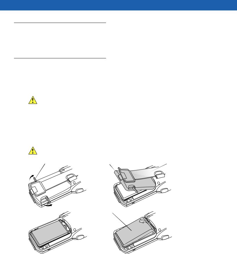
Strap/Door Assembly Removal and Replacement (MC3000S/R)
The Strap/Door Assembly consists of a hand strap and the battery door. There are two versions of this assembly, one for the Standard Battery and one for the Extended Life Battery. Before removing the Strap/Door Assembly, press the red Power button to turn off the screen and set the mobile computer to suspend mode.
To remove the Strap/Door Assembly:
1.Rotate the latches to the open position.
CAUTION Do not lift up on the latches when removing the Strap/Door Assembly. Lift up on the Hand Strap only.
2.Lift the Hand Strap to lift the Strap/Door Assembly off, bottom first.
3.Use a #00 Phillips screwdriver to remove the screws.
4.Lift the mounting clip.
5.Slide the mounting clip out of the strap loop.
Reverse the procedure to replace the Strap/Door Assembly.
 Loading...