


Symbol LS1203
Product Reference Guide
Symbol LS1203
Product Reference Guide
72E-73953-04
Revision A
August 2008

ii Symbol LS1203 Product Reference Guide
© 2008 by Motorola, Inc. All rights reserved.
No part of this publication may be reproduced or used in any form, or by any electrical or mechanical means, without permission in writing from Motorola. This includes electronic or mechanical means, such as photocopying, recording, or information storage and retrieval systems. The material in this manual is subject to change without notice.
The software is provided strictly on an “as is” basis. All software, including firmware, furnished to the user is on a licensed basis. Motorola grants to the user a non-transferable and non-exclusive license to use each software or firmware program delivered hereunder (licensed program). Except as noted below, such license may not be assigned, sublicensed, or otherwise transferred by the user without prior written consent of Motorola. No right to copy a licensed program in whole or in part is granted, except as permitted under copyright law. The user shall not modify, merge, or incorporate any form or portion of a licensed program with other program material, create a derivative work from a licensed program, or use a licensed program in a network without written permission from Motorola. The user agrees to maintain Motorola’s copyright notice on the licensed programs delivered hereunder, and to include the same on any authorized copies it makes, in whole or in part. The user agrees not to decompile, disassemble, decode, or reverse engineer any licensed program delivered to the user or any portion thereof.
Motorola reserves the right to make changes to any software or product to improve reliability, function, or design.
Motorola does not assume any product liability arising out of, or in connection with, the application or use of any product, circuit, or application described herein.
No license is granted, either expressly or by implication, estoppel, or otherwise under any Motorola, Inc., intellectual property rights. An implied license only exists for equipment, circuits, and subsystems contained in Motorola products.
MOTOROLA and the Stylized M Logo and Symbol and the Symbol logo are registered in the US Patent & Trademark Office. Bluetooth is a registered trademark of Bluetooth SIG. Microsoft, Windows and ActiveSync are either registered trademarks or trademarks of Microsoft Corporation. All other product or service names are the property of their respective owners.
Motorola, Inc.
One Motorola Plaza
Holtsville, New York 11742-1300
http://www.motorola.com/enterprisemobility
Patents
This product is covered by one or more of the patents listed on the website:
http://www.motorola.com/enterprisemobility/patents
Warranty
For the complete Motorola hardware product warranty statement, go to: http://www.motorola.com/enterprisemobility/warranty

iii
Revision History
Changes to the original manual are listed below:
Change |
Date |
Description |
|
|
|
-01 Rev A |
1/2006 |
Initial release. |
|
|
|
-02 Rev A |
3/2006 |
Guide format updates. No content changes. |
|
|
|
-03 Rev A |
1/2008 |
Motorola rebranding, add hands free stand assembly instructions, |
|
|
add new UPC/EAN supplemental options and Bookland ISBN format option. |
|
|
|
-04 Rev A |
8/2008 |
Add HD model, change UCC/EAN-128 code type name to GS1-128. |
|
|
|

iv Symbol LS1203 Product Reference Guide

Table of Contents
About This Guide |
|
Introduction .................................................................................................................... |
xi |
Configurations................................................................................................................ |
xi |
Chapter Descriptions ..................................................................................................... |
xi |
Notational Conventions.................................................................................................. |
xii |
Related Documents ....................................................................................................... |
xiii |
Service Information........................................................................................................ |
xiii |
Chapter 1: Getting Started |
|
Introduction ................................................................................................................... |
1-1 |
Unpacking ..................................................................................................................... |
1-2 |
Setting Up the Scanner ................................................................................................. |
1-2 |
Installing the Interface Cable .................................................................................. |
1-2 |
Removing the Interface Cable ................................................................................ |
1-3 |
Connecting Power (if required) ............................................................................... |
1-3 |
Assembling the Hands Free Stand ......................................................................... |
1-4 |
Configuring the Scanner ......................................................................................... |
1-5 |
Chapter 2: Scanning |
|
Introduction ................................................................................................................... |
2-1 |
Beeper Definitions ........................................................................................................ |
2-2 |
LED Definitions ............................................................................................................. |
2-3 |
Scanning ....................................................................................................................... |
2-3 |
Aiming ..................................................................................................................... |
2-4 |
Decode Zones .............................................................................................................. |
2-6 |
Symbol LS1203-SR Standard Range ..................................................................... |
2-6 |
Symbol LS1203-HD High Density ........................................................................... |
2-7 |
Chapter 3: Maintenance & Technical Specifications |
|
Introduction ................................................................................................................... |
3-1 |
Maintenance ................................................................................................................. |
3-1 |

vi Symbol LS1203 Product Reference Guide
Troubleshooting ............................................................................................................ |
3-2 |
Technical Specifications ............................................................................................... |
3-5 |
Scanner Signal Descriptions ......................................................................................... |
3-6 |
Chapter 4: User Preferences |
|
Introduction ................................................................................................................... |
4-1 |
Scanning Sequence Examples ..................................................................................... |
4-1 |
Errors While Scanning .................................................................................................. |
4-2 |
User Preferences Parameter Defaults .......................................................................... |
4-2 |
User Preferences .......................................................................................................... |
4-3 |
Default Parameters ................................................................................................. |
4-3 |
Beeper Tone ........................................................................................................... |
4-4 |
Beeper Volume ....................................................................................................... |
4-4 |
Power Mode ............................................................................................................ |
4-5 |
Scanning Mode ....................................................................................................... |
4-5 |
Scan Line Width ...................................................................................................... |
4-6 |
Laser On Time ........................................................................................................ |
4-6 |
Beep After Good Decode ........................................................................................ |
4-7 |
Transmit Code ID Character ................................................................................... |
4-7 |
Prefix/Suffix Values ................................................................................................. |
4-8 |
Scan Data Transmission Format ............................................................................ |
4-8 |
FN1 Substitution Values ......................................................................................... |
4-10 |
Transmit “No Read” Message ................................................................................. |
4-10 |
Chapter 5: Keyboard Wedge Interface |
|
Introduction ................................................................................................................... |
5-1 |
Connecting a Keyboard Wedge Interface ..................................................................... |
5-2 |
Keyboard Wedge Parameter Defaults .......................................................................... |
5-3 |
Keyboard Wedge Host Parameters .............................................................................. |
5-4 |
Keyboard Wedge Host Types ................................................................................. |
5-4 |
Keyboard Wedge Country Types (Country Codes) ................................................ |
5-5 |
Ignore Unknown Characters ................................................................................... |
5-6 |
Keystroke Delay ...................................................................................................... |
5-7 |
Intra-Keystroke Delay ............................................................................................. |
5-7 |
Alternate Numeric Keypad Emulation ..................................................................... |
5-8 |
Caps Lock On ......................................................................................................... |
5-8 |
Caps Lock Override ................................................................................................ |
5-9 |
Convert Wedge Data .............................................................................................. |
5-9 |
Function Key Mapping ............................................................................................ |
5-10 |
FN1 Substitution ..................................................................................................... |
5-10 |
Send Make and Break ............................................................................................ |
5-11 |
Keyboard Maps ....................................................................................................... |
5-11 |
ASCII Character Set for Keyboard Wedge ................................................................... |
5-12 |
Chapter 6: RS-232 Interface |
|
Introduction ................................................................................................................... |
6-1 |
Connecting an RS-232 Interface .................................................................................. |
6-2 |
Table of Contents |
vii |
|
|
RS-232 Parameter Defaults .......................................................................................... |
6-3 |
RS-232 Host Parameters .............................................................................................. |
6-4 |
RS-232 Host Types ................................................................................................. |
6-6 |
Baud Rate ............................................................................................................... |
6-7 |
Parity ....................................................................................................................... |
6-8 |
Stop Bit Select ........................................................................................................ |
6-9 |
Data Bits (ASCII Format) ........................................................................................ |
6-9 |
Check Receive Errors ............................................................................................. |
6-10 |
Hardware Handshaking .......................................................................................... |
6-10 |
Software Handshaking ............................................................................................ |
6-12 |
Host Serial Response Time-out .............................................................................. |
6-13 |
RTS Line State ........................................................................................................ |
6-14 |
Beep on <BEL> ....................................................................................................... |
6-14 |
Intercharacter Delay ................................................................................................ |
6-15 |
Nixdorf Beep/LED Options ...................................................................................... |
6-16 |
Ignore Unknown Characters ................................................................................... |
6-16 |
ASCII Character Set for RS-232 ................................................................................... |
6-17 |
Chapter 7: USB Interface |
|
Introduction ................................................................................................................... |
7-1 |
Connecting a USB Interface ......................................................................................... |
7-2 |
USB Parameter Defaults .............................................................................................. |
7-3 |
USB Host Parameters .................................................................................................. |
7-4 |
USB Device Type .................................................................................................... |
7-4 |
USB Country Keyboard Types (Country Codes) .................................................... |
7-5 |
USB Keystroke Delay ............................................................................................. |
7-7 |
USB CAPS Lock Override ...................................................................................... |
7-7 |
USB Ignore Unknown Characters ........................................................................... |
7-8 |
Emulate Keypad ...................................................................................................... |
7-8 |
USB Keyboard FN 1 Substitution ............................................................................ |
7-9 |
Function Key Mapping ............................................................................................ |
7-9 |
Simulated Caps Lock .............................................................................................. |
7-10 |
Convert Case .......................................................................................................... |
7-10 |
ASCII Character Set for USB ........................................................................................ |
7-11 |
Chapter 8: Symbologies |
|
Introduction ................................................................................................................... |
8-1 |
Scanning Sequence Examples ..................................................................................... |
8-1 |
Errors While Scanning .................................................................................................. |
8-2 |
Symbology Parameter Defaults .................................................................................... |
8-2 |
UPC/EAN ...................................................................................................................... |
8-5 |
Enable/Disable UPC-A/UPC-E ............................................................................... |
8-5 |
Enable/Disable UPC-E1 .......................................................................................... |
8-6 |
Enable/DisaGS1ble EAN-13/EAN-8 ....................................................................... |
8-7 |
Enable/Disable Bookland EAN ............................................................................... |
8-7 |
Decode UPC/EAN/JAN Supplementals .................................................................. |
8-8 |
User-Programmable Supplementals ....................................................................... |
8-11 |
UPC/EAN/JAN Supplemental Redundancy ............................................................ |
8-11 |

viii Symbol LS1203 Product Reference Guide
Transmit UPC-A Check Digit .................................................................................. |
8-12 |
Transmit UPC-E Check Digit .................................................................................. |
8-12 |
Transmit UPC-E1 Check Digit ................................................................................ |
8-13 |
UPC-A Preamble .................................................................................................... |
8-13 |
UPC-E Preamble .................................................................................................... |
8-14 |
UPC-E1 Preamble .................................................................................................. |
8-15 |
Convert UPC-E to UPC-A ....................................................................................... |
8-15 |
Convert UPC-E1 to UPC-A ..................................................................................... |
8-16 |
EAN-8/JAN-8 Extend .............................................................................................. |
8-16 |
Bookland ISBN Format ........................................................................................... |
8-17 |
UCC Coupon Extended Code ................................................................................. |
8-18 |
Code 128 ...................................................................................................................... |
8-18 |
Enable/Disable Code 128 ....................................................................................... |
8-18 |
Enable/Disable GS1-128 (formerly UCC/EAN-128) ................................................ |
8-19 |
Enable/Disable ISBT 128 ........................................................................................ |
8-19 |
Code 39 ........................................................................................................................ |
8-20 |
Enable/Disable Code 39 ......................................................................................... |
8-20 |
Enable/Disable Trioptic Code 39 ............................................................................ |
8-20 |
Convert Code 39 to Code 32 .................................................................................. |
8-21 |
Code 32 Prefix ........................................................................................................ |
8-21 |
Set Lengths for Code 39 ......................................................................................... |
8-22 |
Code 39 Check Digit Verification ............................................................................ |
8-23 |
Transmit Code 39 Check Digit ................................................................................ |
8-23 |
Code 39 Full ASCII Conversion .............................................................................. |
8-24 |
Code 39 Buffering (Scan & Store) .......................................................................... |
8-24 |
Code 93 ........................................................................................................................ |
8-27 |
Enable/Disable Code 93 ......................................................................................... |
8-27 |
Set Lengths for Code 93 ......................................................................................... |
8-27 |
Code 11 ........................................................................................................................ |
8-28 |
Code 11 .................................................................................................................. |
8-28 |
Set Lengths for Code 11 ......................................................................................... |
8-29 |
Code 11 Check Digit Verification ............................................................................ |
8-30 |
Transmit Code 11 Check Digits .............................................................................. |
8-30 |
Interleaved 2 of 5 (ITF) ................................................................................................. |
8-31 |
Enable/Disable Interleaved 2 of 5 ........................................................................... |
8-31 |
Set Lengths for Interleaved 2 of 5 ........................................................................... |
8-31 |
I 2 of 5 Check Digit Verification ............................................................................... |
8-33 |
Transmit I 2 of 5 Check Digit ................................................................................... |
8-33 |
Convert I 2 of 5 to EAN-13 ...................................................................................... |
8-34 |
Discrete 2 of 5 (DTF) .................................................................................................... |
8-34 |
Enable/Disable Discrete 2 of 5 ................................................................................ |
8-34 |
Set Lengths for Discrete 2 of 5 ............................................................................... |
8-35 |
Chinese 2 of 5 ............................................................................................................... |
8-36 |
Enable/Disable Chinese 2 of 5 ................................................................................ |
8-36 |
Codabar (NW - 7) ......................................................................................................... |
8-36 |
Enable/Disable Codabar ......................................................................................... |
8-36 |
Set Lengths for Codabar ......................................................................................... |
8-37 |
CLSI Editing ............................................................................................................ |
8-38 |
NOTIS Editing ......................................................................................................... |
8-38 |
MSI ............................................................................................................................... |
8-39 |
Table of Contents |
ix |
|
|
Enable/Disable MSI ................................................................................................ |
8-39 |
Set Lengths for MSI ................................................................................................ |
8-39 |
MSI Check Digits .................................................................................................... |
8-40 |
Transmit MSI Check Digit(s) ................................................................................... |
8-41 |
MSI Check Digit Algorithm ...................................................................................... |
8-41 |
GS1 DataBar (formerly RSS, Reduced Space Symbology) ......................................... |
8-42 |
Convert GS1 DataBar to UPC/EAN ........................................................................ |
8-43 |
Symbology - Specific Security Levels ........................................................................... |
8-44 |
Redundancy Level .................................................................................................. |
8-44 |
Security Level ......................................................................................................... |
8-46 |
Bi-directional Redundancy ...................................................................................... |
8-47 |
Symbology - Intercharacter Gap ................................................................................... |
8-47 |
Chapter 9: 123Scan |
|
Introduction ................................................................................................................... |
9-1 |
Communication with 123Scan ...................................................................................... |
9-1 |
123Scan Parameter ...................................................................................................... |
9-1 |
Appendix A: Standard Defaults |
|
Appendix B: Programming Reference |
|
Symbol Code Identifiers ................................................................................................ |
B-1 |
AIM Code Identifiers ..................................................................................................... |
B-2 |
Appendix C: Sample Bar Codes |
|
Code 39 ........................................................................................................................ |
C-1 |
UPC/EAN ...................................................................................................................... |
C-1 |
UPC-A, 100% .......................................................................................................... |
C-1 |
EAN-13, 100% ........................................................................................................ |
C-1 |
Code 128 ...................................................................................................................... |
C-2 |
Interleaved 2 of 5 .......................................................................................................... |
C-2 |
GS1 DataBar ................................................................................................................ |
C-3 |
GS1 DataBar-14 ..................................................................................................... |
C-4 |
Appendix D: Numeric Bar Codes |
|
Numeric Bar Codes ...................................................................................................... |
D-1 |
Cancel ........................................................................................................................... |
D-3 |
Appendix E: ASCII Character Sets
Index

x Symbol LS1203 Product Reference Guide

About This Guide
Introduction
The Symbol LS1203 Product Reference Guide provides general instructions for setting up, operating, maintaining, and troubleshooting the Symbol LS1203 scanner.
Configurations
This guide includes the following configurations:
•Symbol LS1203-SR - Standard range scanning
•Symbol LS1203-HD - High density scanning
Chapter Descriptions
Topics covered in this guide are as follows:
•Chapter 1, Getting Started provides a product overview, unpacking instructions, and cable connection information.
•Chapter 2, Scanning describes parts of the scanner, beeper and LED definitions, and how to use the scanner in triggered and Auto-ScanTM modes.
•Chapter 3, Maintenance & Technical Specifications provides information on how to care for the scanner, troubleshooting, and technical specifications.
•Chapter 4, User Preferences includes programming bar codes for selecting user preference features for the scanner and commonly used bar codes to customize how the data is transmitted to the host device.
•Chapter 5, Keyboard Wedge Interface provides information for setting up the scanner for Keyboard Wedge operation.
•Chapter 6, RS-232 Interface provides information for setting up the scanner for RS-232 operation.
•Chapter 7, USB Interface provides information for setting up the scanner for USB operation.

xiiSymbol LS1203 Product Reference Guide
•Chapter 8, Symbologies describes all symbology features and provides the programming bar codes necessary for selecting these features for the scanner.
•Chapter 9, 123Scan (PC based scanner configuration tool) provides the bar code that must be scanned to communicate with the 123Scan program.
•Appendix A, Standard Defaults provides a table of all host devices and miscellaneous scanner defaults.
•Appendix B, Programming Reference provides a table of AIM code identifiers, ASCII character conversions, and keyboard maps.
•Appendix C, Sample Bar Codes includes sample bar codes.
•Appendix D, Numeric Bar Codes includes the numeric bar codes to scan for parameters requiring specific numeric values.
•Appendix E, ASCII Character Sets provides ASCII character value tables.
Notational Conventions
•Italics are used to highlight chapters and sections in this and related documents
•Bold text is used to highlight the following:
•Key names on a keypad.
•bullets (•) indicate:
•Action items
•Lists of alternatives
•Lists of required steps that are not necessarily sequential
•Sequential lists (e.g., those that describe step-by-step procedures) appear as numbered lists.
•Throughout the programming bar code menus, asterisks (*) are used to denote default parameter settings.
* Indicates Default 
 *Baud Rate 9600
 Feature/Option
NOTE This symbol indicates something of special interest or importance to the reader. Failure to read the note will not result in physical harm to the reader, equipment or data.
CAUTION This symbol indicates that if this information is ignored, the possibility of data or material damage may occur.
WARNING! This symbol indicates that if this information is ignored the possibility that serious personal injury may occur.

About This Guide xiii
Related Documents
The Symbol LS1203 Quick Reference Guide (p/n 72-73954-xx) provides general information to help the user get started with the scanner. It includes basic operation instructions and start up bar codes.
For the latest version of this guide and all guides, go to: http://www.motorola.com/enterprisemobility/manuals.
Service Information
If you have a problem with your equipment, contact Motorola Enterprise Mobility Support for your region. Contact information is available at: http://www.motorola.com/enterprisemobility/contactsupport.
When contacting Enterprise Mobility Support, please have the following information available:
•Serial number of the unit
•Model number or product name
•Software type and version number.
Motorola responds to calls by E-mail, telephone or fax within the time limits set forth in support agreements.
If your problem cannot be solved by Motorola Enterprise Mobility Support, you may need to return your equipment for servicing and will be given specific directions. Motorola is not responsible for any damages incurred during shipment if the approved shipping container is not used. Shipping the units improperly can possibly void the warranty.
If you purchased your Enterprise Mobility business product from a Motorola business partner, contact that business partner for support.

xiv Symbol LS1203 Product Reference Guide
Chapter 1 Getting Started
Introduction
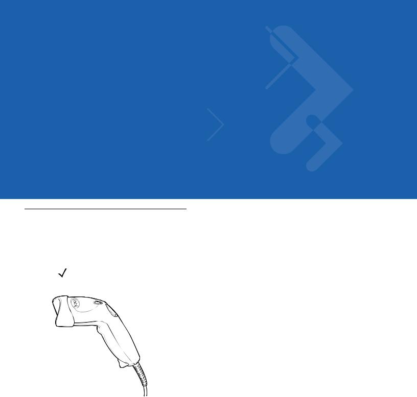
The scanner combines excellent scanning performance and advanced ergonomics to provide the best value in a lightweight laser scanner. Whether used in triggered mode or Auto-ScanTM mode, the scanner ensures comfort and ease of use for extended periods of time.
NOTE The scanner does not support PDF417 bar codes and its variants.
Figure 1-1 LS1203 Scanner
This scanner supports the following interfaces:
•Keyboard Wedge connection to a host. The host interprets scanned data as keystrokes. This interface supports the following international keyboards (for Windows® environment): North America, German, French, French Canadian, Spanish, Italian, Swedish, UK English, Portuguese-Brazilian, and Japanese.
•Standard RS-232 connection to a host. Scan bar code menus to set up proper communication of the scanner with the host.
•USB connection to a host. The scanner autodetects a USB host and defaults to the HID keyboard interface type. Select other USB interface types by scanning programming bar code menus.This interface supports the
1 - 2 Symbol LS1203 Product Reference Guide
following international keyboards (for Windows® environment): North America, German, French, French Canadian, Spanish, Italian, Swedish, UK English, Portuguese-Brazilian, and Japanese.
Unpacking
Remove the scanner from its packing and inspect it for damage. If the scanner was damaged in transit, call Motorola Enterprise Mobility Support. See page xiii for contact information. KEEP THE PACKING. It is the approved shipping container and should be used if the equipment ever needs to be return for servicing.
Setting Up the Scanner
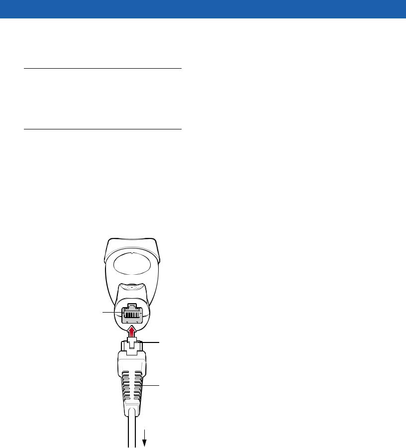
Installing the Interface Cable
To connect the interface cable:
1.Insert the interface cable’s modular connector clip into the cable interface port on the bottom of the scanner handle. (See Figure 1-2.)
2.Gently tug the cable to ensure the connector is properly secured.
3.Connect the other end of the interface cable to the host. (See the specific host chapter for information on host connections.)
Cable interface port
Interface cable modular connector clip
Interface cable
modular connector 

Interface cable strain relief
To host
Figure 1-2 Installing the Cable
Getting Started |
1 - 3 |
|
|
NOTE Different cables are required for different hosts. The connectors illustrated in each host chapter are examples only. Actual connectors may be different than those illustrated, but the steps to connect the scanner remain the same.
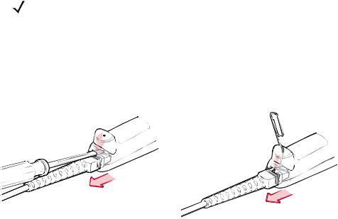
Removing the Interface Cable
To remove the interface cable:
1.Unplug the installed cable modular connector by depressing the connector clip with the tip of a screwdriver, or a paper clip as shown in Figure 1-3.
Figure 1-3 Removing the Interface Cable
2.Carefully slide out the cable.
3.Follow the steps for Installing the Interface Cable on page 1-2 to connect a new cable.
Connecting Power (if required)
If the host does not provide power to the scanner, an external power connection to the scanner is required. To connect power:
1.Connect the interface cable to the bottom of the scanner, as described in Installing the Interface Cable on page 1-2.
2.Connect the other end of the interface cable to the host (refer to the host manual to locate the correct port).
3.Plug the power supply into the power jack on the interface cable. Plug the other end of the power supply into an AC outlet.
1 - 4 Symbol LS1203 Product Reference Guide
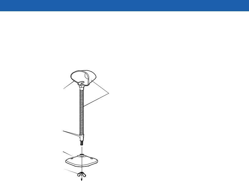
Assembling the Hands Free Stand
1.Unscrew the wingnut from the bottom of the flexible neck.
2.Fit the bottom of the neck piece into the opening on the top of the stand base. When positioned correctly, the flat areas of the neck piece fit into place in the stand base opening.
3.Tighten the wingnut underneath the base to secure the cup and neck piece to the base.
4.Bend the neck to the desired position for scanning.
Auto-scan bar code |
|
(under cup) |
One piece scanner “cup” |
|
with flexible neck. |
Flat areas
Stand base
Wingnut
Figure 1-4 Hands Free Stand Parts
Set Auto-scan Mode
To enable hands free scanning, scan the Auto-scan Mode bar code on the back of the cup to set the scanner to auto-scan mode.
Getting Started |
1 - 5 |
|
|
Mount Stand (Optional)
Attach the base of the scanner stand to a flat surface using two screws or double-sided tape.
NOTE Screws and double-sided tape are not provided.
Two screw-mount holes
Rectangular tape holders (3 places) (dimensions = 1” x 2”)
Figure 1-5 Scanner Mount Stand
Screw Mount
1.Position the assembled base on a flat surface.
2.Screw one #10 wood screw into each screw-mount hole until the base of the stand is secure.
Tape Mount
1.Peel the paper liner off one side of each piece of tape and place the sticky surface over each of the three rectangular tape holders.
2.Peel the paper liner off the exposed sides of each piece of tape and press the stand on a flat surface until it is secure.
Configuring the Scanner
To configure the scanner, use the bar codes included in this manual, or the 123Scan configuration program.
See Chapter 4, User Preferences and Chapter 8, Symbologies for information about programming the scanner using bar code menus. Also see each host-specific chapter to set up a connection to a specific host type.
See Chapter 9, 123Scan to configure the scanner using this configuration program. A help file is available in the program.

1 - 6 Symbol LS1203 Product Reference Guide

Chapter 2 Scanning
Introduction
This chapter provides beeper and LED definitions, techniques involved in scanning bar codes, general instructions and tips about scanning, and decode zone diagrams.
|
LED |
|
Scan |
Trigger |
|
Button |
||
Window |
||
|
Figure 2-1 Parts

2 - 2 Symbol LS1203 Product Reference Guide
Beeper Definitions
The scanner issues different beep sequences and patterns to indicate status. Table 2-1 defines beep sequences that occur during both normal scanning and while programming the scanner.
Table 2-1 Beeper Definitions
Beeper Sequence |
Indication |
|
|
Standard Use |
|
|
|
Low/medium/high beeps |
Power up. |
|
|
Short high beeps |
A bar code symbol was decoded (if decode beeper is |
|
enabled). |
|
|
4 long low beeps |
A transmission error was detected in a scanned symbol. The |
|
data is ignored. This occurs if a unit is not properly |
|
configured. Check option setting. |
|
|
5 low beeps |
Conversion or format error. |
|
|
Low/high/low beeps |
Advanced Data Formatting (ADF) transmit error. (For |
|
information about ADF programming, refer to the Advanced |
|
Data Formatting Programmer Guide, p/n 72-69680-xx.) |
|
|
High/high/high/low beeps |
RS-232 receive error. |
|
|
Parameter Menu Scanning |
|
|
|
Short high beeps |
Correct entry scanned or correct menu sequence performed. |
|
|
Low/high beeps |
Input error, incorrect bar code or “Cancel” scanned, wrong |
|
entry, incorrect bar code programming sequence; remain in |
|
program mode. |
|
|
High/low beeps |
Keyboard parameter selected. Enter value using bar code |
|
keypad. |
|
|
High/low/high/low beeps |
Successful program exit with change in the parameter |
|
setting. |
|
|
Low/high/low/high beeps |
Out of host parameter storage space. Scan Default |
|
Parameters on page 4-3. |
|
|
Code 39 Buffering |
|
|
|
High/low beeps |
New Code 39 data was entered into the buffer. |
|
|
3 Beeps - long high beeps |
Code 39 buffer is full. |
|
|
Low/high/low beeps |
The Code 39 buffer was erased or there was an attempt to |
|
clear or transmit an empty buffer. |
|
|
Low/high beeps |
A successful transmission of buffered data. |
|
|

Scanning 2 - 3
Table 2-1 Beeper Definitions (Continued)
Beeper Sequence |
Indication |
|
|
Host Specific |
|
|
|
USB only |
|
|
|
4 short high beeps |
Scanner has not completed initialization. Wait several |
|
seconds and scan again. |
|
|
Scanner gives a power-up beep after |
Communication with the bus must be established before the |
scanning a USB Device Type. |
scanner can operate at the highest power level. |
|
|
This power-up beep occurs more than once. |
The USB bus may put the scanner in a state where power to |
|
the scanner is cycled on and off more than once. This is |
|
normal and usually happens when the host cold boots. |
|
|
RS-232 only |
|
|
|
1 short high beep |
A <BEL> character is received and Beep on <BEL> is |
|
enabled. |
|
|
LED Definitions
In addition to beeper sequences, the scanner communicates with the user using a two-color LED display. Table 2-2 defines LED colors that display during scanning.
Table 2-2 Standard LED Definitions
LED |
Indication |
|
|
Off |
No power is applied to the scanner, or the scanner is on and ready to scan. |
|
|
Green |
A bar code was successfully decoded. |
|
|
Red |
A data transmission error or scanner malfunction occurred. |
|
|
Scanning
The scanner can operate in two scanning modes: triggered mode and Auto-ScanTM mode. In triggered mode the trigger button must be pressed to emit the scanner laser in order to a scan bar code. In Auto-ScanTM mode the scanner laser is in constant on state and no trigger button press is required to scan a bar code.
To toggle between scanning modes, scan Triggered/Auto-ScanTM on page 4-5.
•If the scanner is in triggered mode, scan Triggered/Auto-ScanTM on page 4-5 to switch to Auto-ScanTM mode.
•If the scanner is in Auto-ScanTM mode, scan Triggered/Auto-ScanTM on page 4-5 to switch to triggered mode.
NOTE When the scanner is not used for an extended period of time in Auto-ScanTM mode, it enters sleep mode. To wake the scanner, press the trigger button.
2 - 4 Symbol LS1203 Product Reference Guide
To scan a bar code:
1.Install and program the scanner (see Setting Up the Scanner on page 1-2). For assistance, contact the local supplier or Motorola Enterprise Mobility Support on page xiii.
2.Ensure all connections are secure. (See the host chapter for the scanner.)
3.Aim the scanner at the bar code.
4.If the scanner is in triggered mode, press the trigger button. (In Auto-ScanTM mode, no trigger button press is required. The scanner laser is in constant on mode.)
|
|
|
|
|
|
|
|
|
|
|
|
|
|
|
|
|
|
Auto-ScanTM Mode |
||
Triggered Mode |
|
|||||
|
||||||
|
||||||
Figure 2-2 Scanning - Triggered and Auto-ScanTM Modes
5.Upon successful decode, the scanner beeps and the LED turns green. (For more information about beeper and LED definitions, see Table 2-1 and Table 2-2.)
NOTE Scan line lengths vary depending on the scan line width selected (see Scan Line Width on page 4-6). A full scan line width is the default. The medium scan line width is useful for scanning menus or pick-lists.
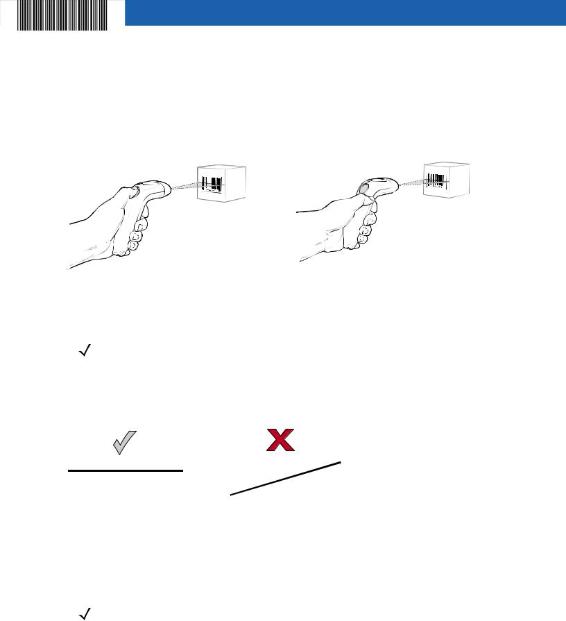
Aiming
On a typical UPC 100% bar code symbol, hold the scanner between contact and 7 inches from the symbol (see Decode Zones on page 2-6). Ensure the scan line crosses every bar and space of the symbol.
|
012345 |
012345 |
Figure 2-3 Acceptable and Incorrect Aiming
The scan line is smaller when the scanner is closer to the symbol and larger when it is farther from the symbol. Scan symbols with smaller bars or elements (mil size) closer to the scanner and those with larger bars or elements (mil size) farther from the scanner.
Do not hold the scanner directly over the bar code. Laser light reflecting directly back into the scanner from the bar code is known as specular reflection. Specular reflection can make decoding difficult.
NOTE Scan line lengths vary depending on the scan line width selected. A full scan line width is the default. The medium scan line width is useful for scanning menus or pick-lists.
For more information about scan line widths, see page 4-6.
Scanning 2 - 5
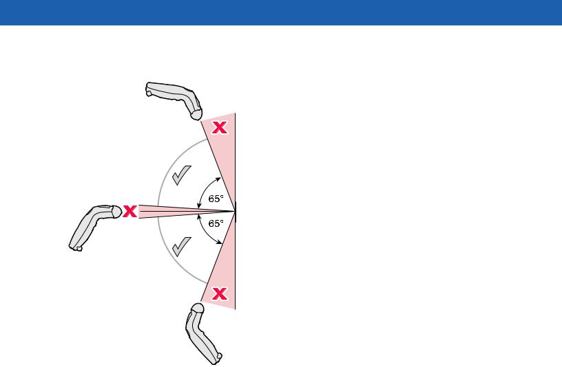
The scanner can be tilted up to 65° forward or back and achieve a successful decode (Figure 2-4). Simple practice quickly shows what tolerances to work within.
Figure 2-4 Maximum Tilt Angles and Dead Zone

2 - 6 Symbol LS1203 Product Reference Guide
Decode Zones
Symbol LS1203-SR Standard Range
Figure 2-5 Symbol LS1203-SR Standard Range Decode Zone
Scanning 2 - 7
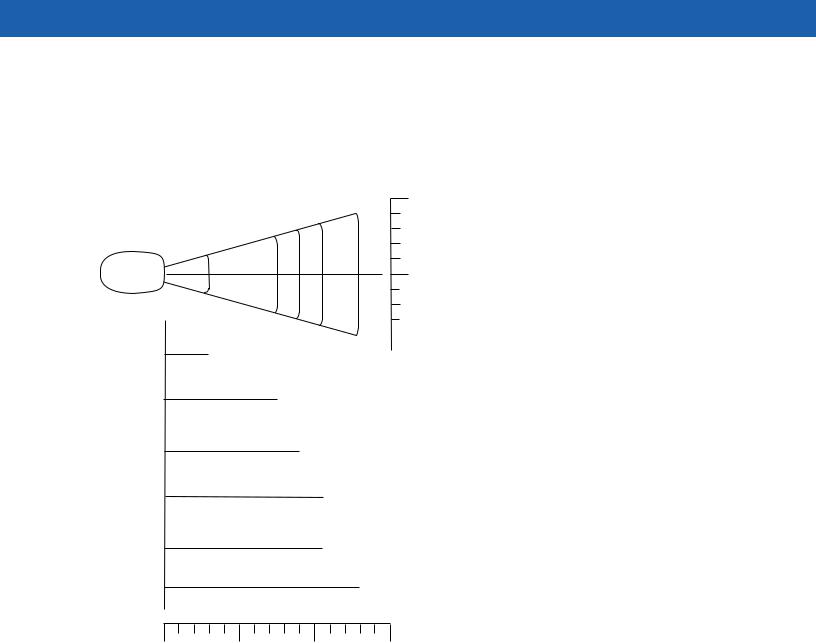
Symbol LS1203-HD High Density
Note: Typical performance at 73° F (23° C) on |
in. cm |
|
high quality symbols in normal room light. |
||
|
2.5 6.35
LS1203-HD |
0 |
0 |
|
3 mil |
|
1.5” |
|
|
|
|
|
|
|
|
2.5 |
6.35 |
|
|
|
|
|
|
|
|
|
|
||||
|
|
|
|
|
|
|
|
|
|
||||
|
|
|
|
|
|
|
|
|
|
||||
|
|
|
|
|
|
|
|
|
|
|
|
|
|
|
5 mil |
|
3.75” |
|
|
|
|
|
|||||
|
|
|
|
|
|
|
|||||||
|
|
|
|
|
|
|
|
|
|
||||
|
|
|
7.5 mil |
|
|
|
|
|
|
||||
|
|
|
|
|
4.5” |
|
|
|
|
|
|||
|
|
|
|
|
|
|
|
||||||
|
|
|
10 mil |
|
|
|
|
|
|
|
|||
|
|
|
|
|
|
5.25” |
|
|
|
|
|
||
|
|
|
|
|
|
|
|
|
|||||
|
13 mil 100% UPC |
|
|
|
|
|
|
||||||
|
|
5.25” |
|
|
|
|
|
||||||
|
|
|
|
|
|
|
|||||||
|
|
|
|
|
|
|
|||||||
|
|
|
|
|
|
|
|
|
|
|
|
||
* |
|
|
20 mil |
|
6.63” |
|
|||||||
|
|
|
|
|
|
||||||||
|
|
|
|
|
|
||||||||
|
|
|
|
||||||||||
|
|
|
|
|
|
|
|
|
|||||
|
|
|
|
|
|
|
|
|
|||||
|
|
|
|
|
|
|
|
|
|
|
|
|
|
|
|
|
|
|
|
|
|
|
|
|
|
|
|
W i d t h
o f
F i e l d
in. 0 |
2.5 |
5 |
7.5 |
cm 0 |
6.35 |
12.7 |
19.1 |
Depth of Field
*Minimum distance determined by symbol length and scan angle
Figure 2-6 Symbol LS1203-HD High Density Decode Zone

2 - 8 Symbol LS1203 Product Reference Guide
 Loading...