


Motorola DSR-6400 Series
Satellite Multiplex Receiver/
Transcoder Operator Guide
DSR-6400
MESSAGE
Document No.: 583611-001
WARNING
The unauthorized modification of any unit and the sale and use of any such unit is prohibited by law. Any such modification or alteration of this product or any unauthorized reception of television programming could subject the user and seller and party modifying the unit to fines, imprisonment, and civil damages.
NOTE: This equipment has been tested and found to comply with the limits for a Class A digital device, pursuant to Part 15 of the FCC Rules. These limits are designed to provide reasonable protection against harmful interference when the equipment is operated in a commercial environment. This equipment generates, uses and can radiate radio frequency energy and, if not installed and used in accordance with the instruction manual, may cause harmful, interference to radio communications. Operation of this equipment in a residential area is likely to cause harmful interference in which case the user will be required to correct the interference at his own expense. This digital apparatus does not exceed the Class A limits of radio noise emissions from digital apparatus set out in the Radio Interference Regulations of the Canadian Department of Communications.
Repairs and Assistance
For assistance on return or repair see "Product Support" on page 79.
Note to CATV System Installer
This reminder is provided to call the CATV system installer’s attention to Article 820-40 of the National Electric Code (NEC) that provides guidelines for proper grounding and, in particular, specifies that the cable ground shall be connected to the grounding system of the building, as close to the point of cable entry as practical.
Warning
To prevent electrical shock, do not use the unit electrical power plug (polarized) with an extension cord, receptacle, or other outlet unless the blades can be fully inserted to prevent blade exposure. The mains disconnect device is the appliance plug and it shall remain readily accessible and operable.
The lithium battery is not field-replaceable for the life of the product.
General Instrument Corporation doing business as Motorola Mobility, Inc.
6450 Sequence Dr. San Diego, CA 92121
DOCUMENT No: 583611-001 REV B, 2/2/12
OPERATION PRECAUTIONS
WARNING: TO PREVENT FIRE OR SHOCK HAZARD, DO NOT EXPOSE THIS EQUIPMENT TO RAIN OR MOISTURE.
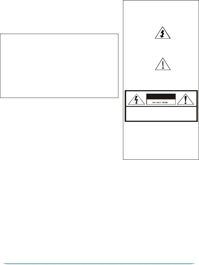
The lightning flash with the arrowhead symbol, within an equilateral triangle, is intended to alert the user to the presence of un-insulated “dangerous voltage” within the product’s enclosure that may be of sufficient magnitude to constitute a risk of electric shock to persons.
The exclamation point within an equilateral triangle is intended to alert the user to the presence of important operating and maintenance (servicing) instructions in the literature accompanying the product.
CAUTION
RISK OF ELECTRIC SHOCK
CAUTION: TO REDUCE THE RISK OF ELECTRIC SHOCK, DO NOT REMOVE COVER (OR BACK).
NO USER-SERVICEABLE PARTS INSIDE.
REFER SERVICING TO QUALIFIED SERVICE PERSONNEL.
ATTENTION
This commercial unit is intended for the decoding of DigiCipher® II television signals for commercial use. Possession of this device does not enable or entitle the possessor to receive DigiCipher II television signals. Contact program providers to obtain appropriate authorizations.
MOTOROLA and the Stylized M Logo are trademarks or registered trademarks of Motorola Trademark Holdings, LLC. All other trademarks are the property of their respective owners.
Dolby Digital is a registered trademark of Dolby Laboratories. Dolby Digital is manufactured under license from Dolby Laboratories.
© 2012 Motorola Mobility, Inc. All rights reserved.
2

Important Safety Instructions
•Read these instructions.
•Keep these instructions.
•Heed all warnings.
•Follow all instructions.
•Do not use this apparatus near water.
•Clean only with dry cloth.
•Do not block any ventilation openings. Install in accordance with the manufacturer’s instructions.
•Do not install near any heat sources such as radiators, heat registers, stoves, or other apparatus (including amplifiers) that produce heat.
•Do not defeat the safety purpose of the polarized or grounding-type plug. A polarized plug has two blades with one wider than the other. A grounding-type plug has two blades and a third grounding prong. The wide blade or the third prong is provided for your safety. If the provided plug does not fit into your outlet, consult an electrician for replacement of the obsolete outlet.
•Protect the power cord from being walked on or pinched, particularly at plugs, convenience receptacles, and the point where they exit from the apparatus.
•Use only attachments and accessories specified by the manufacturer.
DSR-6400 Series
•Unplug this apparatus during lightning storms or when unused for long periods of time.
•Refer all servicing to qualified service personnel. Servicing is required when the apparatus has been damaged in any way, such as when the power-supply cord or plug is damaged, liquid has been spilled, or objects have fallen into the apparatus, the apparatus has been exposed to rain or moisture, does not operate normally, or has been dropped.
Damage Requiring Service
Unplug this equipment from the power source, and contact a qualified service provider if any of the following situations occurs:
•If the power supply cord or plug is damaged.
•If liquid or objects have fallen into the unit.
•If the unit became wet from rain or water.
•If the unit was dropped or damaged.
•If the unit’s performance changes.
Service
Do not try to service this product yourself. If you open or remove the cover, you may be exposed to dangerous voltage or other hazards and may void the unit’s warranty. Contact a qualified service provider for all service.
3
ADVERTENCIA
La modificación no autorizada de cualquier unidad, y la venta y el uso del mismo está prohibida por ley. Cualquier modificación o alteración de este producto o cualquier recepción no autorizada de programación de televisión puede someter al usuario y al vendedor, y a la parte que modifica la unidad a multas, prisión y daños civiles.
NOTA: Este equipo se ha probado y se ha demostrado que cumple con los límites para un dispositivo digital clase A, según la parte 15 de las normas de la FCC. Estos límites están diseñados para ofrecer protección adecuada contra interferencia dañina cuando el equipo se utiliza en un entorno comercial. Este equipo genera, usa y puede irradiar energía de radiofrecuencia y, si no se instala y usa de acuerdo con el manual de instrucciones, puede causar interferencia dañina a las comunicaciones por radio. Es posible que el funcionamiento de este equipo en un área residencial cause interferencia dañina, en cuyo caso el usuario deberá corregir la interferencia y asumir el costo correspondiente. Este aparato digital no supera los límites de la clase A de emisiones de ruido de radio del aparato digital establecido en las Normas de interferencia de radio del Departamento canadiense de comunicaciones.
Reparación y asistencia
Para recibir ayuda sobre devolución o reparación, consulte “Product Support” en la página 79.
Nota para el instalador del sistema CATV
Este recordatorio es para que el instalador del sistema CATV considere el Artículo 820-40 del Código eléctrico nacional (NEC) que entrega pautas para una correcta conexión a tierra y, en especial, especifica que la conexión a tierra del cable debe conectarse al sistema de conexión a tierra del edificio, lo más cerca posible del punto de entrada del cable.
Advertencia
Para evitar descargas eléctricas, no use el enchufe eléctrico de la unidad (polarizado) con un cable de extensión, receptáculo u otra salida a menos que las aspas queden completamente insertadas para evitar la exposición de las aspas. El dispositivo de desconexión de la red de suministro es el enchufe del aparato y debe ser de fácil acceso y estar en funcionamiento.
La batería de litio no se reemplaza en la instalación para mantener la vida útil del producto.
General Instrument Corporation comercializa como Motorola Mobility, Inc.
6450 Sequence Dr. San Diego, CA 92121
N°. DE DOCUMENTO: 583611-001 REV B, 2/2/12
PRECAUCIONES DE OPERACIÓN
ADVERTENCIA: PARA EVITAR RIESGOS DE INCENDIOS O DESCARGA ELÉCTRICA, NO EXPONGA ESTE EQUIPO A LA LLUVIA O LA HUMEDAD.
El símbolo del rayo con cabeza de flecha, dentro de un triángulo equilátero, está diseñado para alertar al usuario la presencia de "voltaje peligroso" sin aislamiento dentro del perímetro del producto que puede tener la magnitud suficiente para ser un riesgo de descarga eléctrica para las personas.
El signo de exclamación dentro de un triángulo equilátero está diseñado para alertar al usuario la presencia de importantes instrucciones de funcionamiento y mantenimiento (servicio) en la literatura que acompaña al producto.
PRECAUCIÓN
RIESGO DE DESCARGA
ELÉCTRICA. NO ABRIR.
PRECAUCIÓN: PARA REDUCIR EL RIESGO DE DESCARGA ELÉCTRICA, NO RETIRE LA CUBIERTA (O LA TAPA). EN EL INTERIOR NO H AY PIEZAS QUE SEAN PARA USO DEL USUARIO.
SOLICITE ASISTENCIA TÉCNICA AL PERSONAL DE SERVICIO CALIFICADO.
ATENCIÓN
Esta unidad comercial está diseñada para decodificar señales de televisión DigiCipher® II para uso comercial. La posesión de este dispositivo no permite ni autoriza al dueño a recibir señales de televisión DigiCipher II. Comuníquese con los proveedores de programa para obtener las autorizaciones correspondientes.
MOTOROLA y el logotipo de la M estilizada son marcas comerciales o marcas comerciales registradas de Marcas Participantes de Motorola LLC. Todas las demás marcas comerciales son propiedad de sus respectivos dueños.
Dolby Digital es una marca comercial registrada de Dolby Laboratories. Dolby Digital está fabricado bajo la licencia de Dolby Laboratories.
© 2012 Motorola Mobility, Inc. Todos los derechos reservados.
4

Instrucciones de seguridad importantes
•Lea estas instrucciones.
•Guarde estas instrucciones.
•Considere todas las instrucciones.
•Siga todas las instrucciones.
•No use este aparato cerca del agua.
•Limpie sólo con un paño seco.
•No bloquee las aberturas de ventilación. Instale siguiendo las instrucciones del fabricante.
•No instale cerca de fuentes de calor como radiadores, rejillas de aire caliente, cocinas u otros aparatos que produzcan calor (incluidos amplificadores).
•No impida el propósito de seguridad del enchufe polarizado o con conexión a tierra. Un enchufe polarizado tiene dos aspas, una más ancha que la otra. Un enchufe de conexión a tierra tiene dos aspas y una tercera punta con conexión a tierra. El aspa ancha o la tercera punta está diseñada para su seguridad. Si el enchufe incluido no se ajusta a la salida, pida al electricista el repuesto de la salida obsoleta.
•Todos los servicios de mantenimiento deben realizarlos personal calificado. El servicio de mantenimiento se requiere cuando el aparato tiene algún daño, por ejemplo cuando el cable de alimentación o enchufe está dañado, se ha derramado líquido o el aparato ha sido golpeado por otros objetos, cuando se ha expuesto a lluvia o humedad, no funciona normalmente o se ha caído.
DSR-6400 Series
•Proteja el cable de alimentación para evitar pisarlo o que quede apretado, especialmente en los enchufes y tomas de corriente, y revise el punto de salida del aparato.
•Use exclusivamente los accesorios especificados por el fabricante.
•Desconecte el aparato durante tormentas eléctricas o cuando no se use durante un tiempo prolongado.
Daños que requieren servicio de mantenimiento
Desenchufe este equipo de la fuente de alimentación y comuníquese con un proveedor de servicio calificado si se presenta alguna de las siguientes situaciones:
•Si el cable de alimentación o enchufe está dañado.
•Si sobre la unidad ha caído líquido o algún objeto.
•Si la unidad se moja por la lluvia o el agua.
•Si la unidad se golpeó o dañó.
•Si se altera el funcionamiento de la unidad.
Servicio
No intente reparar este producto usted mismo. Si abre o retira la cubierta, es posible que se exponga a voltaje peligroso u otros daños, y anule la garantía de la unidad. Para todo tipo de mantenimiento, comuníquese con un proveedor de servicio calificado.
5

Table of Contents
Chapter 1 Introducing the DSR-6400 Series...................................................................................................... |
13 |
Key Features................................................................................................................................ |
13 |
Model and Transcoding Capacity................................................................................................. |
14 |
PID Mapping................................................................................................................................. |
15 |
Processor / Back Panel Associations........................................................................................... |
16 |
Chapter 2 Connecting the DSR-6400 Series Unit.............................................................................................. |
17 |
Unpacking and Connecting the DSR-6400 Series Unit................................................................ |
17 |
Unpacking .................................................................................................................................... |
18 |
Rack Mounting Guidelines ........................................................................................................... |
19 |
Mechanical Loading .............................................................................................................. |
19 |
Ambient Temperature ........................................................................................................... |
19 |
Circuit Overloading ............................................................................................................... |
19 |
Earth Ground ........................................................................................................................ |
19 |
Battery Replacement ............................................................................................................ |
19 |
Connecting the DSR-6400 Series ................................................................................................ |
20 |
Remote Operation........................................................................................................................ |
21 |
Chapter 3 Operating the DSR-6400 Series........................................................................................................ |
23 |
Using the Front Panel................................................................................................................... |
24 |
Navigating the Menus................................................................................................................... |
25 |
How to Use the Menus................................................................................................................. |
26 |
About Menu........................................................................................................................... |
26 |
Main Menu ............................................................................................................................ |
26 |
Overview of The LCD Panel Menu Tree ...................................................................................... |
27 |
Installation Menus ........................................................................................................................ |
30 |
Manual Tune Menu ...................................................................................................................... |
30 |
ASI Input ...................................................................................................................................... |
31 |
Input Field ............................................................................................................................. |
31 |
GigE Input .................................................................................................................................... |
31 |
Input Field ............................................................................................................................. |
31 |
GigE Input IP Addr Field ....................................................................................................... |
32 |
RF Input ....................................................................................................................................... |
32 |
Input Field ............................................................................................................................. |
32 |
Mode Field ............................................................................................................................ |
33 |
Xpndr Field............................................................................................................................ |
33 |
LFreq Field............................................................................................................................ |
34 |
Modulation Menu.......................................................................................................................... |
35 |
Mode Field ............................................................................................................................ |
35 |
Symbol / Code / Format Fields ............................................................................................. |
35 |
DSR-6400 Series |
7 |

1
Port Menu..................................................................................................................................... |
36 |
ID Field.................................................................................................................................. |
36 |
Mode Field ............................................................................................................................ |
36 |
Sat Field................................................................................................................................ |
37 |
Polar Field............................................................................................................................. |
37 |
Port Config Menu ......................................................................................................................... |
37 |
Port 1 Power Field................................................................................................................. |
37 |
Audio1 and Audio2 Menus ........................................................................................................... |
38 |
AudioMix Field....................................................................................................................... |
38 |
DialNorm/Compress Field ..................................................................................................... |
39 |
Audio1 and Audio2 Gain Menus................................................................................................... |
40 |
Mode Field ............................................................................................................................ |
40 |
Left and Right Fields ............................................................................................................. |
40 |
Alarm Menu .................................................................................................................................. |
41 |
Trigger Field.......................................................................................................................... |
41 |
Test Field .............................................................................................................................. |
41 |
4th Relay Menu (DSR-6404 only) ................................................................................................ |
42 |
Config Field........................................................................................................................... |
42 |
ASI Output Menu.......................................................................................................................... |
42 |
Enable Field .......................................................................................................................... |
42 |
ASI Output Rate Menu ................................................................................................................. |
43 |
ASI1 Field ............................................................................................................................. |
43 |
ASI2 Field ............................................................................................................................. |
43 |
Reset Menu .................................................................................................................................. |
44 |
Reset Type Field................................................................................................................... |
44 |
Factory Defaults Option ........................................................................................................ |
44 |
Power Cycle Option .............................................................................................................. |
44 |
Code Select Field.................................................................................................................. |
45 |
Core Menu.................................................................................................................................... |
47 |
Contrast Field........................................................................................................................ |
47 |
Video Out Menu ........................................................................................................................... |
47 |
525 Field ............................................................................................................................... |
48 |
625 Field ............................................................................................................................... |
48 |
Firmware Menu ............................................................................................................................ |
48 |
Boot:FPGA:High Field........................................................................................................... |
48 |
Upgrade Field........................................................................................................................ |
49 |
Download Menu ........................................................................................................................... |
49 |
File Field................................................................................................................................ |
49 |
Current Field ......................................................................................................................... |
49 |
Rcvd Field ............................................................................................................................. |
49 |
Total Field ............................................................................................................................. |
49 |
DR Menu (Acquisition Recovery) ................................................................................................. |
50 |
MODE Field........................................................................................................................... |
50 |
8

VCT (Virtual Channel Table) Field ........................................................................................ |
50 |
VCN (Virtual Channel Number) Field.................................................................................... |
50 |
PORT Field ........................................................................................................................... |
50 |
Channel Menus ............................................................................................................................ |
51 |
PR Field (DSR-6402, DSR-6403, and DSR-6404 only)........................................................ |
51 |
VCT Field .............................................................................................................................. |
51 |
CHNL Field ........................................................................................................................... |
51 |
Xpndr Field............................................................................................................................ |
53 |
MPEG SELECT Menu.................................................................................................................. |
53 |
PR Field (DSR-6402, DSR-6403, and DSR-6404 only)........................................................ |
53 |
Program Field ....................................................................................................................... |
53 |
AUD1LANG and AUD2LANG Menus........................................................................................... |
54 |
Dspl Field .............................................................................................................................. |
55 |
Left and Right Fields ............................................................................................................. |
55 |
InputMode Field .................................................................................................................... |
56 |
Text Lang Menu ........................................................................................................................... |
56 |
Display Field ......................................................................................................................... |
56 |
Subtitle Field ......................................................................................................................... |
57 |
IP Menus ...................................................................................................................................... |
57 |
10/100 MAC Address Menu ......................................................................................................... |
57 |
10/100 DHCP Menu ..................................................................................................................... |
58 |
DHCP Field ........................................................................................................................... |
58 |
Unit Name Field .................................................................................................................... |
58 |
10/100 IP Address Menu.............................................................................................................. |
58 |
10/100 Subnet Mask Menu .......................................................................................................... |
59 |
10/100 Default Gateway Menu..................................................................................................... |
59 |
Port GigE MAC Address Menu..................................................................................................... |
59 |
GigE IP Address Menu................................................................................................................. |
60 |
GigE Subnet Mask Menu ............................................................................................................. |
60 |
GigE Default Gateway Menu........................................................................................................ |
60 |
GigE TS Mode Menu.................................................................................................................... |
61 |
TS Mode Field....................................................................................................................... |
61 |
DSMCC Field ........................................................................................................................ |
61 |
GigE Output Transport Streams ........................................................................................... |
61 |
GigE Xcoded Dest Addr Menu ..................................................................................................... |
62 |
Xcoded Dest Addr Field ........................................................................................................ |
62 |
Port Field............................................................................................................................... |
62 |
GigE PassThru Dest Addr Menu.................................................................................................. |
62 |
PassThru Dest Addr Field..................................................................................................... |
62 |
Port Field............................................................................................................................... |
62 |
Status Display Menus................................................................................................................... |
63 |
Status0 Menu ............................................................................................................................... |
63 |
Health Field........................................................................................................................... |
63 |
Alarm Trigger Field ............................................................................................................... |
63 |
DSR-6400 Series |
9 |

1
Status1 Menu ............................................................................................................................... |
64 |
FrontPanel Field.................................................................................................................... |
64 |
Input Type Field .................................................................................................................... |
64 |
Status2 Menu ............................................................................................................................... |
65 |
Source Field.......................................................................................................................... |
65 |
Channel Field........................................................................................................................ |
65 |
Quality Field .......................................................................................................................... |
65 |
Status3 Menu ............................................................................................................................... |
65 |
Status4 Menu ............................................................................................................................... |
66 |
Sat Field................................................................................................................................ |
66 |
Freq Field.............................................................................................................................. |
66 |
Symb Field ............................................................................................................................ |
66 |
Code Field............................................................................................................................. |
66 |
Format Field.......................................................................................................................... |
66 |
Status5 Menu ............................................................................................................................... |
66 |
Sync Field ............................................................................................................................. |
67 |
Eb/No Field ........................................................................................................................... |
67 |
Authorize State Field............................................................................................................. |
67 |
Status6 Menu ............................................................................................................................... |
68 |
Memory Field ........................................................................................................................ |
68 |
Flash Field............................................................................................................................. |
68 |
Hard Drive Field .................................................................................................................... |
68 |
Status7(SD) Menu........................................................................................................................ |
69 |
PR Field (DSR-6402, DSR-6403, and DSR-6404 only)........................................................ |
69 |
Vido Frmt Field and Resolution Field.................................................................................... |
69 |
BitRt Field.............................................................................................................................. |
69 |
Status8(SD) Menu........................................................................................................................ |
70 |
PR Field (DSR-6402, DSR-6403, and DSR-6404 only)........................................................ |
70 |
Aud Field............................................................................................................................... |
70 |
Format Field.......................................................................................................................... |
70 |
Mode Field ............................................................................................................................ |
70 |
BitR Field............................................................................................................................... |
70 |
Status9(HD) Menu........................................................................................................................ |
71 |
PR Field (DSR-6402, DSR-6403, and DSR-6404 only)........................................................ |
71 |
Vido Fmt Field....................................................................................................................... |
71 |
Resolutn Field ....................................................................................................................... |
71 |
BitRt Field.............................................................................................................................. |
71 |
Status10(HD) Menu...................................................................................................................... |
71 |
PR Field (DSR-6402, DSR-6403, and DSR-6404 only)........................................................ |
72 |
Aud Field............................................................................................................................... |
72 |
Format Field.......................................................................................................................... |
72 |
Mode Field ............................................................................................................................ |
72 |
BitR Field............................................................................................................................... |
72 |
10
|
Status11 Menu |
............................................................................................................................. |
|
72 |
|
Addr Field.............................................................................................................................. |
|
|
72 |
|
Link Field............................................................................................................................... |
|
|
72 |
|
Status12 Menu ............................................................................................................................. |
|
|
73 |
|
Pointer and ...................................................................................................Quantity Fields |
73 |
||
|
Timestamp ...........................................................................................and Message Fields |
74 |
||
|
Status13 Menu ............................................................................................................................. |
|
|
74 |
|
Pointer and ...................................................................................................Quantity Fields |
74 |
||
|
Timestamp ...........................................................................................and Message Fields |
74 |
||
|
Diagnostic Menus......................................................................................................................... |
75 |
||
|
Menus Field .......................................................................................................................... |
|
75 |
|
|
Clear Cntrs ...................................................................................................................Field |
75 |
||
|
PR Field (DSR ........................................................-6402, DSR-6403, and DSR-6404 only) |
75 |
||
|
Unit Address Menu....................................................................................................................... |
76 |
||
|
TV Pass Card Menu..................................................................................................................... |
76 |
||
|
Audio Test Signal ...............................................................................................................Menu |
76 |
||
|
L1/R1 and ........................................................................................................L2/R2 Fields |
77 |
||
|
Video Test Signal ...............................................................................................................Menu |
77 |
||
|
Pattern Field.......................................................................................................................... |
|
77 |
|
|
Ad Insertion Test ................................................................................................................Menu |
78 |
||
|
Cue Tone Field ..................................................................................................................... |
78 |
||
|
Relay Field ............................................................................................................................ |
|
78 |
|
Chapter 4 |
Product Support ................................................................................................................................ |
|
|
79 |
|
If You Need Help.......................................................................................................................... |
|
79 |
|
|
Calling for Repairs........................................................................................................................ |
80 |
||
Chapter 5 Downlink/L-Band Frequency ..............................................................................Conversion Tables |
81 |
|||
Chapter 6 |
Language Abbreviations ................................................................................................................... |
83 |
||
Chapter 7 |
Diagnostics........................................................................................................................................ |
|
|
85 |
|
Introduction .................................................................................................................................. |
|
|
85 |
|
Viewing the Fast ...................................................................................Fact Diagnostic Screens |
86 |
||
|
Fast Facts .......................................................................................................................... |
1 |
|
87 |
|
Fast Facts .......................................................................................................................... |
2 |
|
89 |
|
Fast Facts .......................................................................................................................... |
3 |
|
90 |
|
Fast Facts ................................................................................................. |
4 |
(Audio 1 and 2) |
92 |
|
Fast Facts .............................................................................................. |
5 |
(10/100 Network) |
93 |
|
Fast Facts ............................................................................................. |
5 |
(Gigabit Ethernet) |
94 |
|
Fast Facts ........................................................................................... |
7 |
(Decoder Address) |
95 |
|
Fast Facts .............................................................................................................. |
8 |
(Inbox) |
96 |
|
Fast Facts ........................................................................................................... |
9 |
(Archive) |
97 |
Chapter 8 DSR-6400 Series Specifications ....................................................................................................... |
99 |
|||
DSR-6400 Series |
11 |

1
Introducing the DSR-6400 Series
The Motorola DSR-6400 Series products are commercial Satellite Receiver/Transcoders, designed for broadcasters and headend operators for receiving digital satellite services. The DSR-6400 Series units will process both high-definition and standard-definition video services. After the DSR-6400 Series units are properly installed and configured, they will be ready to receive authorization and control information from the satellite signal source provider.
Key Features
•Eight RF inputs
•DC-II QPSK and DVB-S2 demodulation
•DigiCipher-II security
•GigE and ASI inputs and outputs (Digital HD and SD output)
•Two analog composite (SD) video output ports. The second (OSD video) is for diagnostic use.
•VBI reinsertion for Closed Captioning
•Two stereo pair audio output
•DTMF output
•Up to four Form-C relays for ad insertion support
•One Form-C relay for fault alarm indication
•Uplink controlled retunes
•Memory: Configuration is saved in nonvolatile memory.
•A two-line, 40-character front panel with a Liquid Crystal Display (LCD)
DSR-6400 Series |
13 |

1
•MPEG-2 HD and/or SD ASI and GigE outputs
•Web Server GUI for remote operation
•Advanced audio processing - Supports pass-through and decoding/decompression of Dolby AC-3 and pass-through of the Dolby E audio compression algorithm
•Message Mailbox - Supports text message delivery from the uplink for display on the IRD’s front panel.
•DPI support - Digital (SCTE-35) ad-splicing message support in both broadcast and unitaddressable formats
•DTMF cue tone and Form-C contact closure relay terminals for each processed service
•Scalable service transcoding - shown in Figure 1-1.
Model and Transcoding Capacity
The DSR-6400 Series includes a range of products differentiated by the number of services the units are able to simultaneously receive and transcode. The DSR-6401 transcodes one service, the DSR6402 transcodes two, the DSR-6403 transcodes three, and the DSR-6404 transcodes four services. For setup purposes, the DSR-6400 Series introduces the concept of "processor" or PR in the user interface. A PR number in the user interface identifies the individual service processor path and the unique configuration settings assigned to (or the status information that pertains to) each programmer service being received in a multi-service unit. Each path transcodes a single service according to its own unique configuration settings.
The DSR-6400 Series provides service transcoding that processes up to four MPEG-4 HD input services into four MPEG-2 HD/SD output service pairs (up to eight total services). Figure 1-1 shows how service capacity varies by model.
DSR-6400 Series Models |
Input |
Resolution |
Bit Rate |
MPEG |
||||||||||||||
|
|
|
|
|
|
|
|
|
|
|
|
|
|
|
Service |
Program ID |
||
|
|
|
|
|
|
|
|
|
|
|
|
|
|
|
||||
DSR-6401 |
|
|
|
|
|
|
|
|
|
|
|
|
|
|
1 |
SD |
CBR |
1 |
|
|
|
|
|
|
|
|
|
|
|
|
HD |
VBR or CBR |
2 |
||||
(one processor) |
|
|
|
|
|
|
|
|
|
|
|
|||||||
DSR-6402 |
|
|
|
|
|
|
|
|
|
|
|
|
|
2 |
SD |
CBR |
3 |
|
|
|
|
|
|
|
|
|
|
HD |
VBR or CBR |
4 |
|||||||
(two processors) |
|
|
|
|
|
|
|
|
||||||||||
DSR-6403 |
|
|
|
|
|
|
|
|
|
|
|
3 |
SD |
CBR |
5 |
|||
|
|
|
|
HD |
VBR or CBR |
6 |
||||||||||||
(three processors) |
|
|
|
|
||||||||||||||
|
DSR-6404 |
|
|
|
|
|
|
|
|
4 |
SD |
CBR |
7 |
|||||
|
|
|
|
|
|
HD |
VBR or CBR |
8 |
||||||||||
|
(four processors) |
|
|
|
||||||||||||||
|
|
|
|
|
|
|
|
|
|
|
|
|
|
|
|
|
|
|
Figure 1-1: DSR-6400 Series Transcoding
Note: For example, on a DSR-6404, if all SD services are disabled in the transcoded output, then programs 1, 3, 5, and 7 will not be output.
14
PID Mapping
The DSR-6400 Series uses a PID mapping scheme for the output services for ASI and GIGE output ports. The following two tables show each of the individual service components and their assigned PID values on each MPEG program. These PID values affect the output ports: ASI OUT 1, ASI OUT 2, and GIGE, as shown below. For multiple instances of the same component type, the unit increments the PID value by one.
PID Assignments: ASI OUT 1 Port
MPEG |
Processor |
Number |
PMT |
Video |
Audio1 |
Audio2 |
DPI |
DSMCC |
Subtitle |
|
Program |
Path |
Format |
||||||||
|
|
|
|
|
|
|
||||
1 |
1 |
Decimal |
256 |
272 |
288 |
289 |
304 |
320 |
336 |
|
Hex |
100 |
110 |
120 |
121 |
130 |
140 |
150 |
|||
|
|
|||||||||
2 |
2 |
Decimal |
512 |
528 |
544 |
545 |
560 |
576 |
592 |
|
Hex |
200 |
210 |
220 |
221 |
230 |
240 |
250 |
|||
|
|
|||||||||
3 |
3 |
Decimal |
768 |
784 |
800 |
801 |
816 |
832 |
848 |
|
Hex |
300 |
310 |
320 |
321 |
330 |
340 |
350 |
|||
|
|
|||||||||
4 |
4 |
Decimal |
1024 |
1040 |
1056 |
1057 |
1072 |
1088 |
1104 |
|
Hex |
400 |
410 |
420 |
421 |
430 |
440 |
450 |
|||
|
|
|||||||||
|
|
|
|
|
|
|
|
|
|
Note: The GIGE port carries the same PID mapping information as the two ASI OUT ports.
|
ASI IN |
ASI OUT 1 |
ASI OUT 2 |
VIDEO OUT OSD VIDEO OUT |
10 / 100 |
GIGE |
|
|
|
ETHERNET |
|
|
|
|
PID Assignments: ASI OUT 2 Port
Program/ |
Transcoded |
Number |
PMT |
Video |
Audio1 |
Audio2 |
DPI |
DSMCC |
Subtitle |
|
Resolution |
From |
Format |
||||||||
|
|
|
|
|
|
|
||||
1 (SD) |
|
Decimal |
256 |
272 |
288 |
289 |
304 |
320 |
336 |
|
ASI1 |
Hex |
100 |
110 |
120 |
121 |
130 |
140 |
150 |
||
|
||||||||||
2 (HD) |
Program 1 |
Decimal |
512 |
528 |
544 |
545 |
560 |
576 |
592 |
|
|
Hex |
200 |
210 |
220 |
221 |
230 |
240 |
250 |
||
|
|
|||||||||
3 (SD) |
|
Decimal |
768 |
784 |
800 |
801 |
816 |
832 |
848 |
|
ASI1 |
Hex |
300 |
310 |
320 |
321 |
330 |
340 |
350 |
||
|
||||||||||
4 (HD) |
Program 2 |
Decimal |
1024 |
1040 |
1056 |
1057 |
1072 |
1088 |
1104 |
|
|
Hex |
400 |
410 |
420 |
421 |
430 |
440 |
450 |
||
|
|
|||||||||
5 (SD) |
|
Decimal |
1280 |
1296 |
1312 |
1313 |
1328 |
1344 |
1360 |
|
ASI1 |
Hex |
500 |
510 |
520 |
521 |
530 |
540 |
550 |
||
|
||||||||||
6 (HD) |
Program 3 |
Decimal |
1536 |
1552 |
1568 |
1569 |
1584 |
1600 |
1616 |
|
|
Hex |
600 |
610 |
620 |
621 |
630 |
640 |
650 |
||
|
|
|||||||||
7 (SD) |
|
Decimal |
1792 |
1808 |
1824 |
1825 |
1840 |
1856 |
1872 |
|
ASI1 |
Hex |
700 |
710 |
720 |
721 |
730 |
740 |
750 |
||
|
||||||||||
8 (HD) |
Program 4 |
Decimal |
2048 |
2064 |
2080 |
2081 |
2096 |
2112 |
2128 |
|
|
Hex |
800 |
810 |
820 |
821 |
830 |
840 |
850 |
||
|
|
|||||||||
DSR-6400 Series |
|
|
|
|
|
|
|
15 |
||
1
Processor / Back Panel Associations
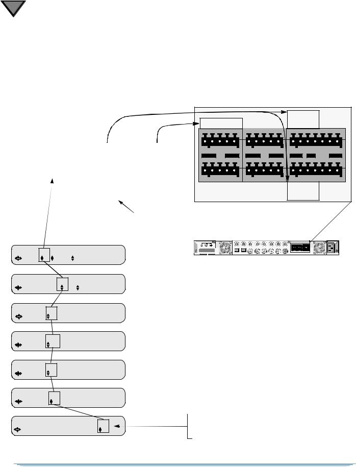
Figure 1-2 shows how Processor numbers (PR) coincide with the Cue Tone ports and Relay ports on the back panel. For example, a DSR-6402 has two processors. The two services use cue tones Q1 (for Processor 1) and Q2 (for Processor 2). To execute Ad insertions, the two processors also use Relay port 1 (for Processor 1) and Relay port 2 port (for Processor 2). Figure 1-2 also shows how all PR fields are linked within the menu system.
Model |
Available |
Relay |
Cue Tone |
||||||
PR Fields |
Ports |
|
Ports |
||||||
|
|
||||||||
DSR-6401 |
(none) |
1, 2, 3 (See Note.) |
|
Q1 |
|||||
|
|
|
|
|
|
|
|
|
|
DSR-6402 |
|
1, 2 |
|
|
1, 2 |
|
|
Q1, Q2 |
|
DSR-6403 |
1, 2, 3 |
1, 2, 3 |
Q1, Q2, Q3 |
||||||
|
|
|
|
|
|
|
|
|
|
DSR-6404 |
1, 2, 3, 4 |
1, 2, 3, [4] |
Q1, Q2, Q3, Q4 |
||||||
|
|
|
|
|
|
|
|
|
|
|
|
RELAY 1 |
ALARM |
|
|
NO CM NC G NO CM NC |
|
Q3+ Q3- G Q4+ Q4- |
L+ L- G R+ R- |
NO CM NC G NO CM NC |
|
|
SECONDARY AUDIO RELAY 2 |
RELAY 3 |
|
If a fourth relay is necessary on a DSR- "4th Relay Menu (DSR-6404 only)" on
CHANNEL |
PR |
VCT |
CHNL Xpndr |
E |
12 |
00000 |
0000 (MPEG mode) |
MPEG SELECT |
PR |
Program |
|
E |
|
12 |
00000(Not in map) |
STATUS7 |
SD PR Vido Frmt Resolutn BitRt |
||||
E |
12 |
MPEG-2 |
720x480 |
6.0M |
|
STATUS8 |
SD PR Aud Format Mode |
BitR |
|||
E |
1 |
0 |
PSTHRU --- |
|
|
|
2 |
|
|
|
--- |
STATUS9 |
HD PR Vido Fmt Resolutn |
BitRt |
|||
E |
2 |
|
|
|
|
|
1 |
MPEG-2 |
1280x720 |
18.0M |
|
STATUS10 HD PR Aud Format Mode |
BitR |
||||
|
2 |
|
|
|
|
E |
1 |
0 |
PSTHRU --- |
--- |
|
DIAG |
Menus |
Clear |
Cntrs PR |
||
E |
Fact 1 |
No |
|
12 |
|
Note: The DSR-6401 has one processor and does not display the PR field on any menu. It also uses three Relay ports (supporting up to three possible ad insertion choices).
The other models have one dedicated relay for each processor (supporting only one ad insertion choice per processor). For more ad insertion choices, use Cue Tones instead.
Changing any one of the PR fields will change all PR fields throughout the entire menu system.
Figure 1-2: Processor / Back Panel Associations
16
2
Connecting the DSR-6400 Series Unit
Unpacking and Connecting the DSR-6400 Series Unit
Cable connections, described in this chapter, are made to the back panel of the unit.
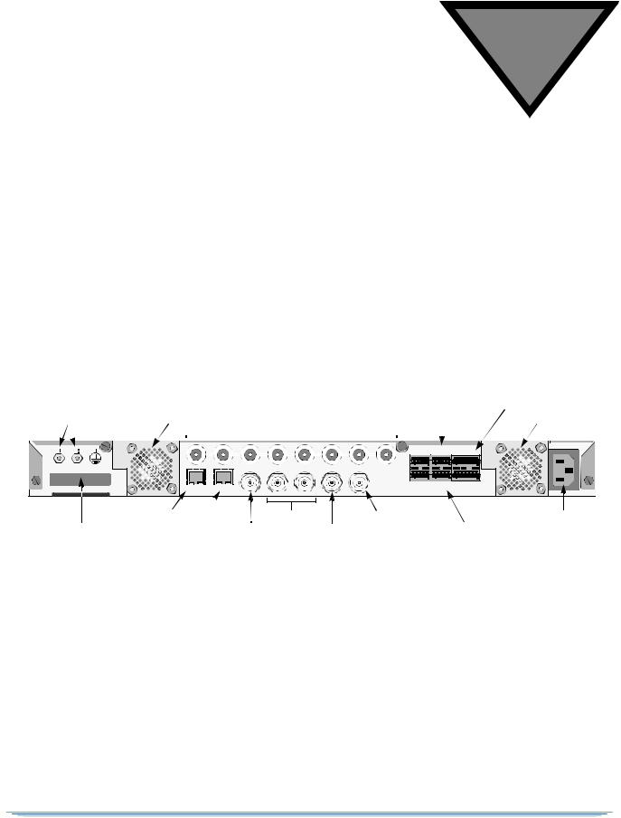
Earth Ground |
|
|
|
L-Band RF Input Ports 1 - 8 |
|
|
|
|
Relay/Alarm |
|||
Terminals |
Fan Unit |
Primary Audio Out |
Fan Unit |
|||||||||
|
|
|
|
|
|
|
|
|
|
|
|
|
|
|
|
|
|
|
|
|
|
|
|
|
|
|
|
|
|
|
|
|
|
|
PRIMARY AUDIO RELAY 1 |
ALARM |
|
|
|
|
|
|
|
|
|
|
|
|
|||
|
|
|
|
|
|
|
|
|
Q1+ Q1- G Q2+Q2- L+ L- G R+ R- NO CM NC |
G NO CM NC |
|
|
|
1 |
2 |
3 |
4 |
5 |
6 |
7 |
8 |
|
|
TVPass® Card |
|
|
|
ASI IN |
ASI OUT 1 ASI OUT 2 |
VIDEO OUT |
|
OUT |
|
RELAY |
CF |
|
|
|
|
|
|
|
|
|
CONTACT |
TYPE |
|
|
|
|
|
|
|
|
RATING 1A |
|
1 |
10 / 100 |
GIGE |
|
|
|
|
|
Q3+ Q3- G Q4+ Q4- L+ L- G R+ R- NO CM NC G NO CM NC |
30 VDC |
|
|
|
|
|
|
|
SECONDARYAUDIO RELAY 2 |
RELAY 3 |
|
||
|
ETHERNET |
|
|
|
|
|
CAUTION: DISCONNECT POWER CORD BEFORE SERVICING |
100-240 VAC, 50 / 60 Hz |
||
|
Ethernet Port |
|
|
|
ASI Out |
|
OSD Video Out |
|
Power Connector |
|
TV Pass Card |
GigE Port |
ASI In |
Video Out |
Secondary Audio Out |
||||||
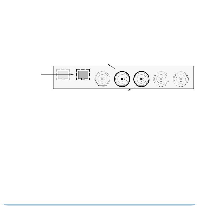
|
Figure 2-1: DSR-6400 Series Back Panel (Overview) |
|
|
|||||||
DSR-6400 Series |
17 |

2
Note: Additional audio and data connectors may be ordered through Phoenix Contact part numbers 1881354 / 1881370.
CAUTION: When connecting any of the eight RF IN ports, the RF-IN Antenna cable should only be connected while the unit is properly grounded and the shield of the coaxial cable should be earthed in accordance with Article 820.93 of the NEC, ANSI/ NFPA 70:2005 or equivalent.
Q1+ Q1- G Q2+Q2- |
PRIMARY AUDIO |
RELAY 1 |
ALARM |
|
||
L+ L- |
G |
R+ R- |
NO CM NC G NO CM NC |
|
||
|
|
|
|
|
|
RELAY |
|
|
|
|
|
|
CONTACT |
|
|
|
|
|
|
RATING 1A |
Q3+ Q3- G Q4+ Q4- |
L+ L- |
G |
R+ R- |
NO CM NC G NO CM NC |
30 VDC |
|
|
SECONDARY AUDIO RELAY 2 |
RELAY 3 |
|
|||
CAUTION: DISCONNECT POWER CORD BEFORE SERVICING |
100-240 VAC, 50 / 60 Hz |
|||||
RF IN
1  2
2  3
3  4
4  5
5  6
6  7
7  8
8
|
ASI IN |
ASI OUT 1 |
ASI OUT 2 |
VIDEO OUT OSD VIDEO OUT |
10 / 100 |
GIGE |
|
|
|
ETHERNET |
|
|
|
|
Figure 2-2: DSR-6400 Series Back Panel (Detailed)
Unpacking
The shipping carton contains the DSR-6400 Series unit, quick disconnect terminals, power cord, mounting brackets, mounting ears, rails, and this Operator Guide.
18

Rack Mounting Guidelines
The DSR-6400 Series unit, with the supplied mounting brackets is designed for installation in an EIA standard 19-inch (480 mm) equipment rack. Place each unit in a stable and level position within the rack and ensure that all front enclosure screws are tightened to 14 inlbs. If multiple DSR-6400 Series units are installed in a rack assembly, the operator may choose to have a certification agency evaluate the condition of the rack.
Mechanical Loading
The mounting rack location should be secure and level to avoid hazardous instability to the equipment due to uneven loading or weight distribution within the rack.
Ambient Temperature
When installing a DSR-6400 Series unit within a closed or multi-unit rack, the ambient temperature may be greater than the ambient temperature within the room. Therefore, verify that the amount of air flow required for safe operation is not compromised (maximum temperature for the equipment is 40° C). Consideration should be given to the maximum rated ambient temperature for the unit’s location when planning for cooling and air circulation. To evacuate the unit’s warm air output from within the mounting rack, Motorola Mobility recommends the use of a fan on top of the rack.
Circuit Overloading
If the unit is connected to a power strip, rather than a branch circuit’s direct connection, use special care to ensure that the unit is properly connected. Always consider the affect that overloading circuits might have on over-current protection and supply wiring. To ensure that circuits are not overloaded, read the DSR-6400 Series UL regulatory power label on top of the unit. Check all equipment power/amperage ratings to ensure the mounting rack power rating is not exceeded.
Earth Ground
Reliable earthing of rack-mounted equipment should be maintained. Particular attention should be given to supply connections other than direct connections to the branch circuit (e.g. use of power strips). The RF-IN antenna cable should only be connected while the unit is properly grounded. The shield of the coaxial cable should be earthed in YP accordance with Article 820.93 of the NEC (National Electrical Code), ANSI/NFPA 70:2005, or equivalent.
Battery Replacement
Do not replace the lithium battery used in the unit. Instead, return the unit to a Motorola Mobility authorized service center for replacement with the same or equivalent type battery as recommended by the manufacturer.
DSR-6400 Series |
19 |

2
Connecting the DSR-6400 Series
To connect a DSR-6400 Series to the GigE signal, see "GigE Input" on page 31. To connect a DSR-6400 Series to an ASI signal, see "ASI Input" on page 31. To connect a DSR-6400 Series to an RF signal:
1.Determine which satellite, transponder, Virtual Channel Table (VCT) number, and Virtual Channel is to be used. Contact the programmer for this system information so that the desired services can be received.
2.Connect the desired L-Band (satellite antenna LNB or LNB signal splitter) source cable to RF Input Port 1 through 8, as directed by the programmer.
Note: LNB power can be enabled for RF Input Port 1.
3.To view video and On-Screen Diagnostics (OSD) during installation, connect the OSD Video Output on the back panel to a 75-ohm video monitor or television with composite video input (standard definition).
Note: The unit generates time-specific ad insertion cue tones and relays. The programmer can include these messages in the encoded signal.
4.If cue tones are needed and made available, connect the differential Cue Tone+, Cue Tone-, and Ground terminals on the unit to the 600-ohm device receiving the tones.
Note: The unit provides an alarm relay that can be used to signal an alarm condition. To indicate an alarm, the unit provides a short-circuit electrical connection between the NC and CM terminals and an open-circuit electrical connection between the NO and CM terminals. With this configuration, the unit is able to signal an alarm, even for the loss of AC power.
5.Plug the unit into a power source. Verify that the LCD screen is lit.
6.Proceed with the installation using the front panel menus.
7.For details on web server GUI, see "Remote Operation" on page 21.
20
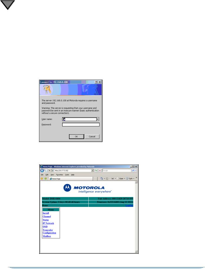
Remote Operation
The DSR-6400 Series decoder can be operated remotely from a web browser. When the decoder is contacted via an HTTP session from a computer, the decoder’s web server responds to the HTTP session with a login dialog box that requires the user to login with user name and password. Once the login is successful, the decoder’s web server then presents the unit’s home page to the browser.
Some of the IRD configuration settings and control inputs that are accessible through HTTP include:
•Virtual channel and audio language selection
•Status and device information (e.g., signal strength, alarms, unit address)
•Soft reset (AC power cycle)
•Settings for acquiring a satellite signal (e.g., transponder frequency, input port)
•Video and audio output customizations
•Alarm triggers
•ASI and Ethernet output customizations
•Complete Transcoder configuration (Read-only when set by uplink programmer)
To configure the DSR-6400 Series unit for remote operation
1.Contact your network administrator for the IP Subnet Mask address, unique IP address, and default gateway address to assign to this decoder.
Caution: By default, all DSR-6400 series units have the same IP address. To use the unit’s remote operation, each unit on the subnet must be assigned a unique IP
address. Failure to assign a unique IP address to each unit on the subnet will result in loss of connectivity.
2.To configure the decoder, use the decoder’s arrow buttons on the front panel to perform the following procedures:
•10/100 IP Address Menu, page 58
•10/100 Subnet Mask Menu, page 59
•10/100 Default Gateway Menu, page 59
3.Use an RJ-45 cable to connect the decoder’s Ethernet 10/100 port to the subnet that will be used to operate the decoder remotely.
DSR-6400 Series |
21 |
2
To operate the DSR-6400 Series decoder remotely
1.Open a browser session, type the decoder’s unique IP address in the address bar, and press the ENTER key.
For example, if the decoder is configured with IP address 10.11.23.60, then go to the browser, type: http://10.11.23.60 in the address bar, and press ENTER.
2.When the login dialog box appears (as shown below), enter the User name and Password and select OK.
Note: The uplink programmer who authorizes the unit has the option to set the User Name and Password. If they authorize the unit without using this option, leave both fields blank and simply select OK to gain access to web-based remote operation. (Blank) is the default User Name and Password.
3.When the Home Page appears (as shown below), use the sidebar menu to access the decoder’s various settings and control features.
22 .
3
Operating the DSR-6400 Series
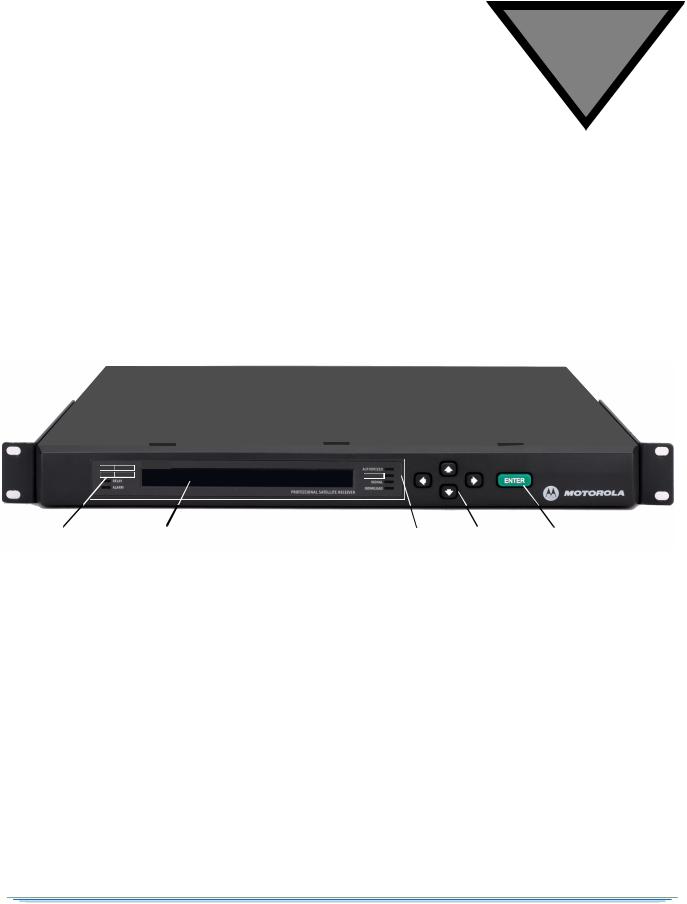
All operations described in this chapter require use of the front panel, as shown in Figure 3-1.
DSR-6400
MESSAGE
|
Relay |
|
LCD Screen |
Authorized Arrow Buttons |
ENTER Button |
|
|
||||
|
|
||||
|
|
||||
|
Alarm |
|
|
Message |
|
|
|
|
|
Signal |
|
|
|
|
|
Download |
|
Figure 3-1: DSR-6400 Series Front Panel
The following list describes the LEDs located on the left and right sides of the LCD screen.
Relay |
Illuminates when relays are activated. |
Alarm |
Illuminates when the unit enters an alarm state. |
Authorized |
Illuminates when the unit is authorized by the service provider. |
Message |
Illuminates when the unit has a mailbox message from the uplink. |
Signal |
Illuminates when the unit is locked to a valid carrier. |
Download |
Blinks when a firmware download is in progress and illuminates solid when |
|
the unit has successfully received the firmware download and is waiting for |
|
activation by the programmer. |
DSR-6400 Series |
23 |
3
Using the Front Panel
The front panel LCD screen displays a series of menus that can be used to configure and control the system. The name of the current menu is always in the upper left corner of the screen for easy identification.
•Beneath every menu name are symbols representing key presses that are possible from the current cursor position in the menu. Note that the available keypad moves may change during the navigation between menu fields.
Menu Name |
Label |
Label |
Label |
E |
Setting |
Setting |
Setting |
•The top row, to the right of the menu name, displays the name of each field available within that menu. These are called field labels and its setting is displayed directly below.
•Beneath each label is the current setting for each field.
•Some fields may be changed by the user and others are for display purposes only. Fields that can be changed have an arrow indicator (  ) just to the left of the field label. During left/right navigation, the cursor skips over the labels that cannot be changed.
24

Navigating the Menus
Even though the keypad options shown on the LCD screen may change for each menu and for each field, the control buttons basically do the same thing. The user may want to practice on a screen to become familiar with how the buttons work. Notice that:
• Pressing the buttons while the cursor is blinking next to the menu name (far left corner), causes the cursor to scroll to another menu.
• Pressing ENTER while the cursor is blinking next to the menu name (far left corner) causes the cursor to scroll to the Main, top-level menu.
• Pressing the 4buttons while in the top line of the menu causes the cursor to move between field labels (or the menu name and a field label).
• Pressing the 4 button at the rightmost field label causes the cursor to wrap to the left side of the screen (to the menu name). Likewise, pressing the button when the cursor is at the menu name causes the cursor to wrap to the rightmost field label.
• When the cursor is blinking on a field label (top row), pressing ENTER causes the cursor to move below the label and enter into the field so the setting can be changed.
• When the cursor is below the label, the displayed directional controls in the left corner show what
buttons can be pressed to change the setting in that field. When the symbol is left of the field, this
indicates the ability to select from the available values. Placing the blinking cursor on those arrows and press the buttons to reveal each of the available choices for that field, one at a time.
•To store changes in a field and move back up to the label line, press ENTER.
DSR-6400 Series |
25 |

3
How to Use the Menus
About Menu
The front-panel LCD displays the About menu when the unit is initially plugged in or after a factory reset. This menu identifies the model (either DSR-6401, DSR-6402, DSR-6403, or DSR-6404) and the second line displays the DSR-6400 Series’s actual firmware version instead of 0xXXXXX, as shown below.
MOTOROLA DSR-6400
Version 0xXXXXX
This menu is displayed for 10 seconds, then the front-panel LCD displays the Main menu.
Main Menu
This menu is the top-level menu and can be accessed from any other menu by pressing ENTER while the cursor is blinking next to the menu name. This menu allows the user to select any one of the five main menu groups: Installation menus, Channel menus, IP menus, Status menus, and Diagnostic menus.
DSR-640X

 E Install Channel IP Status Diag
Note: In the above graphic, the X in DSR-640X designates the exact model (DSR-6401, DSR-6402, DSR-6403, or DSR-6404).
The unit allows the user to scroll ( ) only to menus that are in the same group. To scroll to a menu that is in a different menu group, return to the main top-level menu and select the desired menu group. To return to the main top-level menu from any menu, place the cursor in the upper-left corner and press ENTER.
26
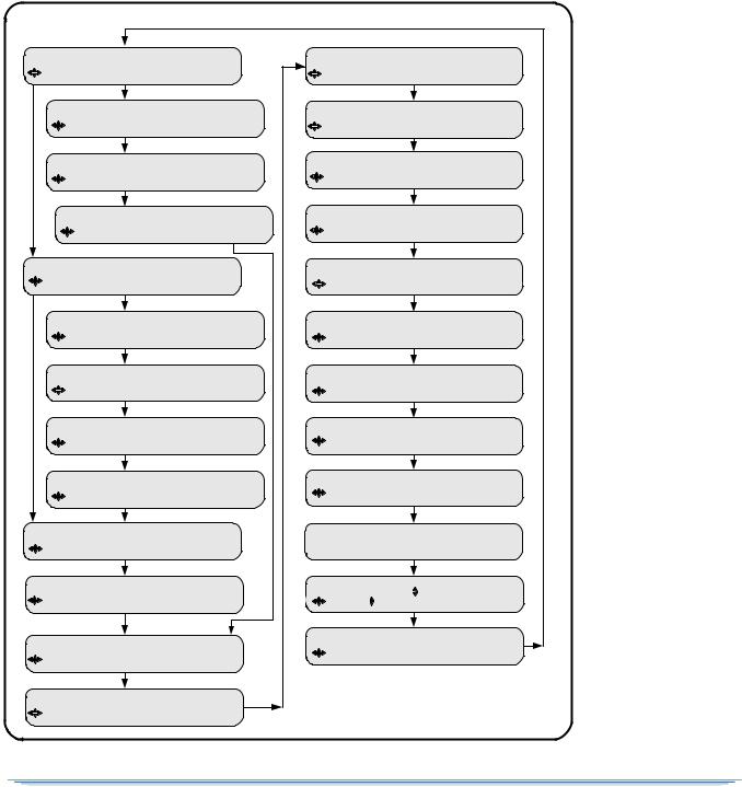
Overview of The LCD Panel Menu Tree
Pressing ENTER when the cursor is on a menu name causes the cursor to return to the main, top level menu. The charts on the following pages show the menus organized into five main groups: Installation menus, Channel selection menus, IP menus, Status menus, and Diagnostic menus.
INSTALLATION MENUS
MANUAL |
TUNE Input |
Mode Xpndr |
LFreq |
||||
E |
|
Port 1 |
Xpndr 01 |
1430.00 |
|||
MANUAL TUNE |
Input |
|
|
|
|||
|
E |
|
ASI In |
|
|
|
|
MANUAL TUNE |
Input |
|
|
|
|||
|
E |
|
GigE In |
|
|
|
|
GigE Input |
|
IP Address |
|
Port |
|||
|
E |
|
|
239.001.001.001 |
00000 |
||
MODULATION |
Mode |
|
|
|
|
||
E |
|
DCII-AUTO |
|
|
|
||
MODULATION |
Mode |
Symbol |
|
||||
|
E |
|
DVBS2 |
30.000000 |
|
||
MODULATION |
Mode |
Symbol |
|
||||
|
E |
|
8PSK-TC |
01.000000 |
|||
MODULATION |
Mode |
Symbol |
|
||||
|
E |
|
DVB-MAN |
01.000000 |
|
||
MODULATION Mode |
Sym |
Code Format |
|||||
|
E |
DCII-MAN |
19.51 |
3/4 |
Comb |
||
PORT ID |
Mode |
Sat |
Polar |
|
|
||
E |
1 |
Auto |
|
--- |
--- |
|
|
PORT CONFIG |
|
|
Port 1 Power |
|
|||
E |
|
|
|
Off |
|
|
|
AUDIO1 |
AudioMix |
|
DialNorm/Compress |
||||
E |
Stereo |
|
On-Moderate |
|
|
||
AUDIO2 |
AudioMix |
|
DialNorm/Compress |
||||
E |
Stereo |
|
On-Moderate |
|
|
||
AUDIO1 GAIN |
Mode |
|
Left |
Right |
|||
E |
|
Joint |
|
+00 |
|
+00 |
|
AUDIO2 GAIN |
Mode |
|
Left |
Right |
|||
E |
|
Joint |
|
+00 |
|
+00 |
|
ALARM |
|
Trigger |
|
Test |
|||
E |
|
Auto |
|
|
Off |
|
|
4th RELAY |
Config |
|
|
|
|
||
E |
|
Alarm |
|
|
|
|
|
ASI OUTPUT |
Enable |
|
|
|
|
||
E |
|
On |
|
|
|
|
|
ASI OUTPUT |
RATE |
ASI1 |
ASI2 |
||||
E |
|
|
78 |
|
108 |
|
|
RESET |
Reset Type |
Code Select |
|||||
E |
No |
|
|
0x333 active |
|||
CORE |
|
Contrast |
|
|
|
||
E |
|
18 |
|
|
|
|
|
VIDEO |
OUT 525 |
625 |
|
|
|
|
|
E |
|
NTSC |
PAL-625 |
|
|
|
|
FIRMWARE Boot:FPGA:High |
Upgrade |
||||||
E |
XXXXXX:XXXXXX:XXXXXX 000000 |
||||||
DOWNLOAD |
File |
Current Rcvd Total |
|||||
E |
|
00 of 00 |
0000 |
0000 0000 |
|||
DR MODE |
VCT |
VCN |
PORT |
||||
E DISABLED (00000) |
---- |
NA |
|
||||
Note: The Modulation, Port, and Port Config menus are only present when one of the RF ports is selected as the input within the Manual Tune menu.
The 4th Relay menu is only present on a DSR-6404.
The GigE Input menu is only present when GigE is selected as the input.
DSR-6400 Series |
27 |
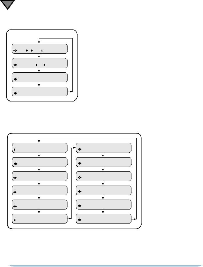
3
Channel Selection Menus
CHANNEL |
PR |
VCT |
CHNL Xpndr |
|||
E |
1 |
00000 |
|
0000 (MPEG mode) |
||
MPEG SELECT |
|
PR |
|
Program |
||
E |
|
|
1 |
|
00000(Not in map) |
|
AUD1LANG |
Dspl Left |
Right InputMode |
||||
E |
All |
def |
|
def |
--- |
|
AUD2LANG |
Dspl |
Left |
Right InputMode |
|||
E |
All |
def |
|
def |
--- |
|
IP MENUS
PORT 10/100 |
MAC Address |
PORT GigE |
IP Address |
|
|
E |
hh:hh:hh:hh:hh:hh |
E |
192.168.054.100 |
|
|
PORT 10/100 |
DHCP |
Unit Name |
PORT GigE |
Subnet Mask |
|
E |
Disable |
DSR640X-XXXXX |
E |
255.255.255.000 |
|
PORT 10/100 |
IP Address |
PORT GigE |
Default Gateway |
|
|
E |
192.168.000.100 |
E |
192.168.054.002 |
|
|
PORT 10/100 |
Subnet Mask |
PORT GigE |
TS Mode |
DSMCC |
|
E |
255.255.255.000 |
E |
Off |
Off |
|
PORT 10/100 |
Default Gateway |
PORT GigE |
Xcoded Dest Addr |
Port |
|
E |
192.168.000.001 |
E |
192.168.054.201 |
06100 |
|
PORT GigE |
MAC Address |
PORT GigE |
PassThru Dest Addr |
Port |
|
E |
hh:hh:hh:hh:hh:hh |
E |
192.168.054.200 |
06000 |
|
28
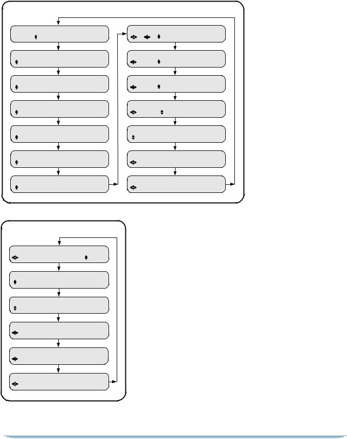
Status Menus
STATUS0 |
Health |
|
Alarm Trigger |
STATUS7 |
SD PR Vido Frmt Resolutn BitRt |
|||||
E |
Acq:Alarm |
Auto |
|
E |
1 |
MPEG-2 |
720x480 |
6.0M |
||
STATUS1 |
FrontPanel |
Input Type |
STATUS8 |
SD PR Aud Format Mode |
BitR |
|||||
E |
Local-Control L-Band |
E |
1 |
0 PSTHRU --- |
--- |
|||||
STATUS2 |
Source |
|
Channel |
Quality |
STATUS9 |
HD PR Vido Fmt Resolutn |
BitRt |
|||
E |
--- |
|
---- |
--- |
E |
1 |
MPEG-2 |
1280x720 |
18.0M |
|
STATUS3 |
Signal Quality |
|
|
STATUS10 |
HD PR Aud Format Mode |
BitR |
||||
E |
|||||||||||||||||||||||....... |
E |
1 |
0 |
PSTHRU --- |
--- |
||||
STATUS4 |
Sat Freq |
Symb |
Code |
Format |
STATUS11 |
Addr Field |
Link Field |
|||
E |
--- 1430.00 11.71 5/6 |
Comb |
E |
---------- |
Off |
|
||||
STATUS5 |
Sync |
Eb/No |
Authorize State |
STATUS12 MAIL: INBOX |
> 0/0 |
|
||||
E |
Tuning -2.0 |
Undefined Service |
E |
|
|
|
|
|||
STATUS6 |
Memory |
Flash |
Hard Drive |
STATUS13 MAIL: ARCHIVE |
> 0/0 |
|
||||
E |
8.0MB |
450.4MB |
14.9GB |
E |
|
|
|
|
||
Diagnostic Menus
DIAG |
Menus |
|
|
PR |
E |
Off |
|
|
1 |
UNIT ADDRESS |
|
|
|
|
E |
|
ddd-ddddd-ddddd-ddd |
||
TV PASS CARD |
Status |
|
||
E |
|
Not Inserted |
|
|
AUDIO TEST SIGNAL |
L1/R1 |
L2/R2 |
||
E |
|
|
Off |
Off |
VIDEO TEST SIGNAL |
Pattern |
|
||
E |
|
|
Off |
|
AD INSERTION |
TEST |
Cue Tone Relay |
||
E |
|
|
Off |
Off |
DSR-6400 Series |
29 |
3
Installation Menus
The purpose of the installation menus is to configure the ports and choose settings that remain fixed over time. This section describes in detail each of the Installation menus, fields, and options displayed on the LCD panel.
Return to the main top-level menu and then select the Installation menu group.
With the blinking cursor at the upper left, press the ENTER button to return to the main top-level menu. Press the 4 buttons until the cursor is at the Install label, and press ENTER. The unit displays the previously-selected sub-menu.
Manual Tune Menu
Use this menu to begin to acquire a DigiCipher II system signal, by selecting a transponder frequency for one of the eight L-Band inputs. In addition, this menu allows a user to select the ASI input or GigE input, as an alternative to RF ports 1 through 8.
MANUAL |
TUNE Input |
Mode Xpndr |
LFreq |
E |
Port 1 |
Xpndr 01 |
1430.00 |
MANUAL |
TUNE Input |
|
|
E |
ASI In |
|
|
MANUAL |
TUNE Input |
|
|
E |
GigE In |
|
|
To specify an RF input port, see "RF Input" on page 32.
To specify the ASI In as the input port, see "ASI Input" on page 31.
To specify the GigE In as the input port, see "GigE Input" on page 31.
30
 Loading...