


 Loading...
CONTENTS |
|
Computer Software Copyrights . . . . . . . . . . . . . |
ii |
Safety . . . . . . . . . . . . . . . . . . . . . . . . . . . . . . . . . . |
iii |
Radio Overview . . . . . . . . . . . . . . . . . . . . . . . . . . |
1 |
LED Colors . . . . . . . . . . . . . . . . . . . . . . . . . . . . . . . |
3 |
LCD Display and Icons . . . . . . . . . . . . . . . . . . . . . . |
4 |
Programmable Buttons. . . . . . . . . . . . . . . . . . . . . . |
5 |
Getting Started . . . . . . . . . . . . . . . . . . . . . . . . . . . |
7 |
Attaching and Removing the Antenna . . . . . . . . . . |
7 |
Attaching and Removing the Battery . . . . . . . . . . . |
8 |
Attaching and Removing the Belt Clip . . . . . . . . . . |
9 |
Charging the Battery. . . . . . . . . . . . . . . . . . . . . . . . |
10 |
Scan . . . . . . . . . . . . . . . . . . . . . . . . . . . . . . . . . . . |
12 |
Deleting a Nuisance Scan Channel . . . . . . . . . . . . |
12 |
Voice Operated Transmit (VOX) . . . . . . . . . . . . . |
13 |
Voice Inversion Scrambling . . . . . . . . . . . . . . . . |
14 |
Front Panel Feature and Button Configuration
Mode . . . . . . . . . . . . . . . . . . . . . . . . . . . . . . . . . . . 15
Entering Front Panel Feature and Button Configuration
Mode . . . . . . . . . . . . . . . . . . . . . . . . . . . . . . . . . . . . 15
Exiting Front Panel Feature and Button Configuration
Mode . . . . . . . . . . . . . . . . . . . . . . . . . . . . . . . . . . . . 15
Assessing Front Panel Feature and Button Configuration
Mode Parameters . . . . . . . . . . . . . . . . . . . . . . . . . . 15
TPL and DPL Frequencies and Codes . . . . . . . . 20
TPL Frequency . . . . . . . . . . . . . . . . . . . . . . . . . . . . 20
DPL Codes . . . . . . . . . . . . . . . . . . . . . . . . . . . . . . . 22
Warranty . . . . . . . . . . . . . . . . . . . . . . . . . . . . . . . . 25
Accessories . . . . . . . . . . . . . . . . . . . . . . . . . . . . . 29
CONTENTS
i |
English |
|
|

COMPUTER SOFTWARE COPYRIGHTS
COMPUTER SOFTWARE
COPYRIGHTS
The Motorola products described in this manual may include copyrighted Motorola computer programs stored in semiconductor memories or other media. Laws in the United States and other countries preserve for Motorola certain exclusive rights for copyrighted computer programs, including, but not limited to, the exclusive right to copy or reproduce in any form the copyrighted computer program. Accordingly, any copyrighted Motorola computer programs contained in the Motorola products described in this manual may not be copied, reproduced, modified, reverse-engineered, or distributed in any manner without the express written permission of Motorola.
Furthermore, the purchase of Motorola products shall not be deemed to grant either directly or by implication, estoppel, or otherwise, any license under the copyrights, patents or patent applications of Motorola, except for the normal non-exclusive license to use that arises by operation of law in the sale of a product.
English ii
SAFETY
PRODUCT SAFETY AND RF EXPOSURE COMPLIANCE
!
C a u t i o n
Before using this product, read the operating instructions for safe usage contained in the Quick Reference Card enclosed with your radio.
ATTENTION!
This radio is restricted to occupational use only to satisfy FCC RF energy exposure requirements. Before using this product, read the RF energy awareness information and operating instructions in the radio’s enclosed Quick Reference Card (Motorola Publication part number 68007024011) to ensure compliance with RF energy exposure limits.
SAFETY
iii English

Notes
SAFETY
English iv

RADIO OVERVIEW
1 Channel Selector Knob |
|
|
2 On/Off and Volume Knob |
9 |
Accessory Connector |
|
10 |
Programming Port |
3 LED Indicator
CP185
4 Speaker
5Microphone
6Liquid Crystal Display (LCD)
11 Left/Right Button
12 Front Programmable Buttons
7 Push-to-Talk (PTT) Button
8 Side Programmable Buttons
OVERVIEW RADIO
1 English

|
1. |
Channel Selector Knob |
|
OVERVIEW |
|
Used to select channels in normal radio operation mode. |
|
2. |
On/Off and Volume Knob |
||
|
|||
|
|
Turn the ON/OFF/Volume Control knob clockwise to turn |
|
|
|
the radio ON. |
|
RADIO |
|
Turn the ON/OFF/Volume Control knob counterclockwise |
|
|
to turn the radio OFF. |
||
|
|
||
|
|
Turn this knob clockwise to increase the volume. |
|
|
|
Turn this knob counterclockwise to decrease the volume. |
|
|
3. |
LED Indicator |
|
|
|||
|
|
Indicates radio transmit, receive, scan and monitor status. |
|
|
|
Refer to "LED Colors" on page 3 for more information. |
|
|
4. |
Speaker |
|
|
|
Receives audio messages through the speaker. |
|
|
5. |
Microphone |
|
|
|
Speak into the microphone when sending messages. |
|
|
6. |
Liquid Crystal Display (LCD) |
|
|
|
An 8 character single line display with up to 9 radio status |
|
|
|
icons. Refer to "LCD Display and Icons" on page 4 for |
|
|
|
more details. |
English 2
7.Push-to-Talk (PTT) Button
Press and speak to microphone to send message. Release and listen to receive messages.
Note: If a channel is programmed with the Busy Channel Lockout feature, the user can only transmit if the channel is not in receiving mode.
8.Side Programmable Buttons
Refer to "Programmable Buttons" on page 5 for more details.
9.Accessory Connector
2.5mm audio in port and 3.5 mm audio out port are used to connect compatible accessories to the radio.
10.Programming Port
2.5mm audio in lower port used by dealer to program the radio.
11.Left/Right Button 

Used to navigate menu, sub-menu or parameter selections in Front Panel Feature and Button Configuration Mode.
12.Front Programmable Buttons 


Refer to "Programmable Buttons" on page 5 for more details.

LED COLORS
LED Color |
State |
Indication |
Green |
Illuminated |
Radio is transmitting in normal |
|
|
mode. |
|
|
Radio is transmitting in |
|
|
Scrambling Mode. |
|
|
|
|
Normal Blinking |
Radio is receiving in normal |
|
|
mode. |
|
|
Channel is busy. |
|
|
Radio passed self-test during |
|
|
powering up. |
Amber |
Illuminated |
Monitor activated. |
|
|
Permanent Sticky Monitor |
|
|
activated. |
|
|
|
|
Normal Blinking |
Radio is in active Scan Mode. |
|
|
Radio is receiving in |
|
|
Scrambling Mode. |
Red |
Normal Blinking |
Radio is transmitting in normal |
|
|
mode while battery is low. |
|
|
Radio is transmitting in |
|
|
Scrambling Mode while battery |
|
|
is low. |
|
|
|
|
Fast Blinking |
Radio failed self-test during |
|
|
powering up. |
|
|
|
OVERVIEW RADIO
3 English
RADIO OVERVIEW
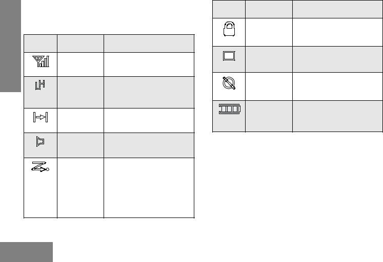
LCD Display and Icons
Displays selected channel, programming parameters, status messages and any error or information messages.
LCD |
Description |
Function |
|
Indicator |
|||
|
|
||
|
Signal Strength |
Shows the signal strength. More |
|
|
Indicator |
bars indicate a stronger signal |
|
|
|
received by radio. |
|
|
Power Level |
“L” illuminates to indicate radio is |
|
|
Indicator |
configured to transmit in low |
|
|
|
power; “H” illuminates when radio |
|
|
|
transmits in high power. |
|
|
Talkaround |
Illuminates when radio is not |
|
|
Indicator |
transmitting through the repeater. |
|
|
Monitor |
Illuminates when monitoring a |
|
|
Indicator |
selected channel. |
|
|
Scan Indicator |
Blinks without dot when normal |
|
|
|
scan is activated. |
|
|
|
Illuminates without dot when |
|
|
|
there is some activity on a |
|
|
|
non-priority channel. |
|
|
|
Illuminates with dot blinking to |
|
|
|
indicate that there is some |
|
|
|
activity on the priority channel. |
LCD |
Description |
Function |
|
Indicator |
|||
|
|
||
|
Voice Inversion |
Illuminates when Scrambling |
|
|
Scrambling |
Mode is on. |
|
|
Indicator |
|
|
|
Programming |
Illuminates when Programming |
|
|
Mode Indicator |
Mode is on. |
|
|
Keypad Lock |
Illuminates when keypad is |
|
|
Indicator |
locked. |
|
|
Battery Level |
Shows remaining charge in |
|
|
Indicator |
battery based on how many bars |
|
|
|
(1 – 3) are displayed. Blinks |
|
|
|
when the battery is low. |
English 4
Programmable Buttons
The programmable buttons consist of:
• Side Programmable Button 1
• Side Programmable Button 2
• Front Programmable Button 1
• Front Programmable Button 2
• Front Programmable Button 3
The following functions can be assigned as short press i.e. press and release; or long press i.e. press and hold for more
than 1 second.
Button |
Function |
Backlight |
Toggles backlight display between ON and OFF. |
|
|
Channel Alias |
Toggles display between Channel Number and |
|
Channel Alias. |
Keypad Lock |
Locks or unlocks all buttons except PTT, Side |
|
Programmable Button 1, Side Programmable |
|
Button 2, Channel Selector Knob and ON/OFF/ |
|
Volume Knob. Applicable for Long Press Only. |
|
|
Button |
Function |
|
|
Monitor |
Monitors the channel for any activity as long as |
|
RADIO |
|
the button is pressed. |
|
|
|
|
|
|
|
|
|
|
Nuisance |
Removes unwanted channel(s) temporarily from |
|
|
Channel Delete |
scan list during Scan. Applicable for Long Press |
|
OVERVIEW |
|
Only. |
|
|
|
|
|
|
TPL/DPL |
Enables or disables radio from requiring |
|
|
Enable |
matching TPL/DPL to unsquelch. |
|
|
|
|
|
|
Power Level |
Selects required power level: High or Low. |
|
|
Reverse Burst |
Select the Reverse Burst Type: None, 180 or |
|
|
|
240. |
|
|
|
|
|
|
Channel Scan |
Starts or stops Channel Scan. |
|
|
Scrambling |
Toggles between the two scrambling codes |
|
|
Code Select |
available. |
|
|
|
|
|
|
Scrambling |
Enables or disables scrambling feature for the |
|
|
Enable/Disable |
selected channel. Applicable for Long Press |
|
|
|
Only. |
|
|
Squelch Level |
Selects desired squelch level: Normal or Tight. |
|
|
|
|
|
|
Sticky Monitor |
Toggles the permanent monitor function until the |
|
|
|
button is pressed again. Applicable for Long |
|
|
|
Press Only. |
|
|
Talkaround/ |
Enables toggle between repeater and |
|
|
Repeater Mode |
talkaround mode operations. |
|
|
|
|
|
|
Unassigned |
No function is programmed to this button. |
|
|
|
|
|
|
5 English

RADIO OVERVIEW
Button |
Function |
Volume Set |
Controls the audio level. A programmable button |
|
used to control the audio level. The button emits |
|
a continuous tone to indicate the current |
|
volume level. To change volume level, turn the |
|
volume knob to the desired level while |
|
pressing the programmable button. Applicable for |
|
Long Press only. |
|
|
VOX |
Enables or disables VOX feature for the selected |
|
channel. |
|
|
The default functions assigned to your radio are described in the table below.
Press |
Side |
Side |
Front |
Front |
Front |
Type |
Button 1 |
Button 2 |
Button 1 |
Button 2 |
Button 3 |
Short |
Unassigned |
Unassigned |
Monitor |
Scan |
Power |
Press |
|
|
|
|
Level |
|
|
|
|
|
|
Long |
Unassigned |
Unassigned |
Sticky |
Nuisance |
Unassigned |
Press |
|
|
Monitor |
Channel |
|
|
|
|
|
Delete |
|
If your dealer has re-programmed your radio’s programmable buttons, you may want to write down the new functions in the
table below.
Press |
Side |
Side |
Front |
Front |
Front |
Type |
Button 1 |
Button 2 |
Button 1 |
Button 2 |
Button 3 |
Short |
|
|
|
|
|
Press |
|
|
|
|
|
Long |
|
|
|
|
|
Press |
|
|
|
|
|
English 6
Loading...