


Broadband

Motorola, Inc. 570510-001-00 rev A Page 1 of 50
-
-
1
1
USER GUIDE
T3 PowerBroadband

Motorola, Inc. 570510-001-00 rev A Page 2 of 50
No part of this publication may be reproduced or transmitted, in any form or by any means, electronic,
mechanical, photocopying, recording, or otherwise, without the prior written consent of the publisher.
Information in this manual is furnished under license and may only be used in accordance with the terms of the
software license. This publication and the information herein is furnished AS IS, is subject to change without
notice, and should not be construed as a commitment by Motorola. Motorola assumes no responsibility or liability
for any errors or inaccuracies, makes no warranty of any kind (expressed, implied, or staory) with respect to this
publication, and expressly disclaims any and all warranties of merchantability, fitness for particular purposes, and
noninfringement of third-party rights.
Companies, names, and data used in the examples herein are fictitious unless otherwise noted.
Pass-Through Licenses:
Net-SNMP Copyright 1989, 1991, 1992, 1996, 1998-2004
LwIP Copyright © 2001, 2002 Swedish Instie of Computer Science
Net-SNMP and LwIP source code are provided under the terms of their respective license agreements.
Source code and copyright notices are available from Motorola support.
email: pbn.support@motorola.com
Copyright © 2005-2006 Motorola, Inc. All rights reserved.
‘Motorola‘ is a registered trademark of Motorola, Inc. in the United States and in other countries.
Other trade names used in this document are trademarks or registered trademarks of the manufacturers or
vendors of the associated products.
Motorola, Inc.
5200 Franklin drive, Suite 100
Pleasanton, CA 94588
1 (925) 201-4500 main
1 (925) 201-4509 fax
1 (800) 998-4888
www.systems.com
Published in the United States of America
August, 2007
T3 PowerBroadband User Guide
Text part number: 570510-001-00 rev A

Motorola, Inc. 570510-001-00 rev A Page 3 of 50
Regulatory Statements
Model Number: 45225
45101
Radio Frequency Interference Requirements- FCC
Note: This equipment has been tested and found to comply with the limits for a Class A digital device, pursuant to
Part 15 of the FCC rules. These limits are designed to provide reasonable protection against harmful interference
when the equipment is operated in commercial environment. This equipment generates, uses, and can radiate
radio frequency energy and, if not installed and used in accordance with the instruction manual, may cause
harmful interference to radio communications. Operation of this equipment in a residential area is likely to cause
harmful interference in which case the user will be required to correct the interference at his own expense.
Radio Frequency Interference Requirements- Canada
This Class A digital apparatus complies with Canadian ICES-003.
Cet appareil numérique de la classe A est conforme à la norme NMB-003 du Canada.
Marking and European Economic Area (EEA)
WARNING: This is a Class A product. In a domestic environment this product may cause radio interference in
which case the user may be required to take adequate measures.
Statement of Compliance
Motorola/Symbol hereby declares that this device is in compliance with all the applicable Directives, 2004/108/EC
and 2006/95/EC. A Declaration of Conformity may be obtained from http://www2.symbol.com/doc/.
Model Number: 45010
Wireless Device Country Approvals
For 2.4GHz or 5GHz Products: Europe includes, Austria, Belgium, Bulgaria, Czech Republic, Cyprus, Denmark,
Estonia, Finland, France, Germany, Greece, Hungary, Iceland, Ireland, Italy, Latvia, Liechtenstein, Lithuania,
Luxembourg, Malta, Netherlands, Norway, Poland, Portugal, Romania, Slovak Republic, Slovenia, Spain,
Sweden, Switzerland and the United Kingdom.
Operation of the device without regulatory approval is illegal.
Frequency of Operation – FCC and IC
2.4 GHz Only
The available channels for 802.11 b/g operation in the US are Channels 1 to 11. The range of channels is limited
by firmware.
RF Exposure Guidelines
Safety Information
Reducing RF Exposure – Use Properly
Only operate the device in accordance with the instructions supplied.
International
The device complies with internationally recognized standards covering human exposure to electromagnetic fields
from radio devices. For information on “International” human exposure to eletromagnic fields refer to the
Motorola/Symbol Declaration of Conformity (DoC) at http://www2.symbol.com/doc/.
EU
Remote and Standalone Antenna Configurations

Motorola, Inc. 570510-001-00 rev A Page 4 of 50
To comply with EU RF exposure requirements, antennas that are mounted externally at remote locations or
operating near users at stand-alone desktop of similar configurations must operate with a minimum separation
distance of 20 cm from all persons.
FCC
Remote and Standalone Antenna Configurations
To comply with FCC RF exposure requirements, antennas that are mounted externally at remote locations or
operating near users at stand-alone desktop of similar configurations must operate with a minimum separation
distance of 20 cm from all persons.
To satisfy FCC RF exposure requirements, a mobile transmitting device must operate with a minimum separation
distance of 20 cm or more from a person’s body.
Radio Frequency Interference Requirements- FCC
Note: This equipment has been tested and found to comply with the limits for a Class A digital device, pursuant to
Part 15 of the FCC rules. These limits are designed to provide reasonable protection against harmful interference
when the equipment is operated in commercial environment. This equipment generates, uses, and can radiate
radio frequency energy and, if not installed and used in accordance with the instruction manual, may cause
harmful interference to radio communications. Operation of this equipment in a residential area is likely to cause
harmful interference in which case the user will be required to correct the interference at his own expense.
Radio Transmitters (Part 15)
This device complies with Part 15 of the FCC Rules. Operation is subject to the following two conditions: (1) this
device may not cause harmful interference, and (2) this device must accept any interference received, including
interference that may cause undesired operation.
Radio Frequency Interference Requirements- Canada
This Class A digital apparatus complies with Canadian ICES-003.
Cet appareil numérique de la classe A est conforme à la norme NMB-003 du Canada.
Radio Transmitters
This device complies with RSS 210 of Industry & Science Canada. Operation is subject to the following two
conditions: (1) this device may not cause harmful interference and (2) this device must accept any interference
received, including interference that may cause undesired operation.
Label Marking: The Term "IC:" before the radio certification only signifies that Industry Canada technical
specifications were met.
Marking and European Economic Area (EEA)
WARNING: This is a Class A product. In a domestic environment this product may cause radio interference in
which case the user may be required to take adequate measures.
The use of 2.4GHz WLAN’s, for use through the EEA, have the following restrictions:
• Maximum radiated transmit power of 100 mW EIRP in the frequency range 2.400 -2.4835 GHz.
• France, outside usage is restricted to 2.4 – 2.454 GHz.
• Italy requires a user license for outside usage.
Statement of Compliance
Motorola/Symbol hereby, declares that this device is in compliance with the essential requirements and other
relevant provisions of Directive 1999/5/EC. A Declaration of Conformity may be obtained from
http://www2.symbol.com/doc/.

Motorola, Inc. 570510-001-00 rev A Page 5 of 50
IMPORTANT SAFETY INSTRUCTIONS
T2-2500 and T3 Switch
CAUTION: For installation only in a Restricted Access Location by trained service personnel.
CAUTION: Equipment must be connected to an earthed mains socket-outlet.
CAUTION: To reduce the risk of fire, use only No. 26 AWG or larger telecommunication line cord.
CAUTION: The power supply cord plug serves as the main disconnect for the product. The socket-outlet shall be
installed near the product and be readily accessible.
CAUTION: Voltages present which are above TNV-3 (POTS) limits. A cover must be installed over the punch
down blocks with a HV (High Voltage) warning label (supplied).
The maximum operating ambient temperature is 50 degrees Celcius.
When installing the Switch in an equipment rack, consider the following potential hazards:
Elevated Operating Ambient Temperature – If installed in a closed or multi-unit rack assembly, the operating
ambient temperature of the rack environment may be greater than the room ambient. Therefore, consideration
should be given to installing the equipment in an environment compatible with the manufacturer’s maximum rated
ambient temperature (Tmra).
Reduced Air Flow – Installation of the equipment in a rack should be such that the amount of air flow required for
safe operation of the equipment is not compromised.
Mechanical Loading – Mounting of the equipment in the rack should be such that a hazardous condition is not
achieved due to uneven mechanical loading.
Circuit Overloading – Consideration should be given to the connection of the equipment to the supply circuit and
the effect that overloading of circuits might have on overcurrent protection and supply wiring. Appropriate
consideration of equipment nameplate ratings should be used when addressing this concern.
Reliable Earthing – Reliable earthing of rack-mounted equipment should be maintained.
Particular attention should be given to supply connections other than direct connections to the branch circuit (e.g.,
use of power strips).
m2 WallPlate
CAUTION: Use only power supplies listed in the user manual
When using your telephone equipment, basic safety precautions should always be followed to reduce the risk of
fire, electric shock and injury to persons, including the following:
1. Do not use this product near water, for example, near a bath tub, wash bowl, kitchen sink or laundry tub,
in a wet basement or near a swimming pool.
2. Avoid using a telephone (other than a cordless type) during an electrical storm. There may be a remote
risk of electric shock from lightning.
3. Do not use the telephone to report a gas leak in the vicinity of the leak.
SAVE THESE INSTRUCTIONS

Motorola, Inc. 570510-001-00 rev A Page 6 of 50
Waste Electrical and Electronic Equipment (WEEE)
English: For EU Customers: All products at the end of their life must be returned to Motorola for recycling. For information on
how to return product, please go to: www.motorola.com/recycling/weee.
Bulgarish: За клиенти от ЕС: След края на полезния им живот всички продукти трябва да се връщат на Motorola за
рециклиране. За информация относно връщането на продукти, моля отидете на адрес:
www.motorola.com/recycling/weee.
Dansk: Til kunder i EU: Alle produkter skal returneres til Motorola til recirkulering, når de er udtjent. Læs oplysningerne om
returnering af produkter på: www.motorola.com/recycling/weee.
Deutsch: Für Kunden innerhalb der EU: Alle Produkte müssen am Ende ihrer Lebensdauer zum Recycling an Motorola
zurückgesandt werden. Informationen zur Rücksendung von Produkten finden Sie unter: www.motorola.com/recycling/weee.
Eesti: EL klientidele: kõik tooted tuleb nende eluea lõppedes tagastada taaskasutamise eesmärgil Motorola'ile.
Lisainformatsiooni saamiseks toote tagastamise kohta külastage palun aadressi: www.motorola.com/recycling/weee.
Español: Para clientes en la Unión Europea: todos los productos deberán entregarse a Motorola al final de su ciclo de vida
para que sean reciclados. Si desea más información sobre cómo devolver un producto, visite:
www.motorola.com/recycling/weee.
Français : Clients de l'Union Européenne : Tous les produits en fin de cycle de vie doivent être retournés à Motorola pour
recyclage. Pour de plus amples informations sur le retour de produits, consultez: www.motorola.com/recycling/weee.
Italiano: per i clienti dell'UE: tutti i prodotti che sono giunti al termine del rispettivo ciclo di vita devono essere restituiti a
Motorola al fine di consentirne il riciclaggio. Per informazioni sulle modalità di restituzione, visitare il seguente sito Web:
www.motorola.com/recycling/weee.
Magyar: Az EU-ban vásárlóknak: Minden tönkrement terméket a Motorola vállalathoz kell eljuttatni újrahasznosítás céljából. A
termék visszajuttatásának módjával www.motorola.com/recycling/weee.
Nederlands: Voor klanten in de EU: alle producten dienen aan het einde van hun levensduur naar Motorola te worden
teruggezonden voor recycling. Raadpleeg www.motorola.com/recycling/weee voor meer informatie over het terugzenden van
producten. www.motorola.com/recycling/weee.
Português: Para clientes da UE: todos os produtos no fim de vida devem ser devolvidos à Motorola para reciclagem. Para
obter informações sobre como devolver o produto, visite: www.motorola.com/recycling/weee.
Românesc: Pentru clienţii din UE: Toate produsele, la sfârşitul duratei lor de funcţionare, trebuie returnate la Motorola pentru
reciclare. Pentru informaţii despre returnarea produsului, accesaţi: www.motorola.com/recycling/weee.
Slovenski: Za kupce v EU: vsi izdelki se morajo po poteku življenjske dobe vrniti podjetju Motorola za reciklažo. Za
informacije o vraèilu izdelka obišèite: www.motorola.com/recycling/weee.
Suomi: Asiakkaat Euroopan unionin alueella: Kaikki tuotteet on palautettava kierrätettäväksi Motorola-yhtiöön, kun tuotetta ei
enää käytetä. Lisätietoja tuotteen palauttamisesta on osoitteessa: www.motorola.com/recycling/weee.
Svenska: För kunder inom EU: Alla produkter som uppnått sin livslängd måste returneras till Motorola för återvinning.
information om hur du returnerar produkten finns på www.motorola.com/recycling/weee.

Motorola, Inc. 570510-001-00 rev A Page 7 of 50
Commands and Syntax 9
Command Hierarchy.................................................................................. 9
Administrative Commands.......................................................................... 9
System Description 12
T3 PowerBroadband Switch .......................................................................12
M2 Ethernet WallPlate...............................................................................12
MC-802 Wireless WallPlate ........................................................................13
Hardware 15
Model Numbers and Description.................................................................15
Model Numbers and Description for related Products.....................................15
T3 PowerBroadband Switch .......................................................................16
MC-802 Wireless WallPlate ........................................................................17
m2 – 2 port Ethernet WallPlate ..................................................................17
System Administration 19
Management Access.................................................................................19
CLI Configuration Script files......................................................................19
Configuration Files using the webUI............................................................20
HTTP Menus............................................................................................21
Upgrading the Firmware............................................................................22
Line Quality.............................................................................................23
View System Configuration and Status........................................................24
Commit mode..........................................................................................25
Reset to Default Configuration ...................................................................25
Other Configuration Help...........................................................................25
Managing the Wireless WallPlates 26
WallPlate Inventory and Firmware Image ....................................................26
IP Addresses ...........................................................................................27
Configuring a WLAN 29
Global Radio Commands ...........................................................................29
Per-WLAN Commands...............................................................................30
Monitor the WLANs and radios ...................................................................30
Access Control Lists (ACLs) 31
RADIUS network authenticated login 32
WallPlate Installation 33
Enable line power.....................................................................................35
Finish the installation................................................................................36
802.1Q VLANs 37

Motorola, Inc. 570510-001-00 rev A Page 8 of 50
VLAN Specification ...................................................................................37
VLAN terminology ....................................................................................37
VLAN commands......................................................................................38
Web UI configuration................................................................................39
Quality of Service (QoS) 42
QoS commands and concepts ....................................................................42
Dynamic packet classification.....................................................................44
QoS Example 45
Line Status 46
Appendix A: Pin-out Assignments 48
Appendix B: Hardware Specifications 49
T3 PowerBroadband ................................................................................. 49
m2 WallPlate...........................................................................................49
MC-802 Wireless WallPlate ........................................................................50

Commands and Syntax
Motorola, Inc. 570510-001-00 rev A Page 9 of 50
C
C
o
o
m
m
m
m
a
a
n
n
d
d
s
s
a
a
n
n
d
d
S
S
y
y
n
n
t
t
a
a
x
x
The Motorola T3 PowerBroadband system can be managed via a Command Line Interface, webUI, and SNMP.
Commands that apply to remote WallPlates, such as Ethernet port configurations and wireless interface, are all
entered on the T3 Switch.
C
C
o
o
m
m
m
m
a
a
n
n
d
d
H
H
i
i
e
e
r
r
a
a
r
r
c
c
h
h
y
y
The Command Line Interface (CLI) implements a hierarchical command structure. Commands are organized as a
high-level command keyword related to a particular function of the device with sub-commands related to sub-
functions.
You may move down in the command hierarchy by entering root keywords and sub-keywords followed by the
enter key. Your current level in the command hierarchy is referred to as the “command context.” The top-level
context is referred to as the “root command context.” You may move up to the previous command context by
using the exit command. The command prompt is the system name, followed by the current command context.
For example, the root command prompt with the default configuration is:
system>
Full commands may be entered at the root command context. For example:
system> interface dsl enable port1
You may also move down levels in the command hierarchy, which allows you to execute commands with less
repetitive typing.
For example:
system> interface
system:interface> dsl
system:interface.dsl> enable port1
system:interface.dsl> enable port3
system:interface.dsl> enable port3
system:interface.dsl> exit
system:interface> exit
system>
A
A
d
d
m
m
i
i
n
n
i
i
s
s
t
t
r
r
a
a
t
t
i
i
v
v
e
e
C
C
o
o
m
m
m
m
a
a
n
n
d
d
s
s
Most commands discussed in this guide are administrative commands, which change the configuration of the
system or affect the operation of the system. These commands can only be executed from the admin account.
Configuration changes take affect immediately and are recorded in non-volatile memory (NVRAM) in the default
mode. Alternatively, you may choose not to record changes in NVRAM. In this case, changes will need to be
committed before rebooting the system; otherwise the configuration will revert to the last saved configuration. If
automatic commit is enabled, or the configuration is manually committed, the running configuration will
automatically be restored if the system power cycles or is rebooted.
Show Commands
The show commands are used to view configurations, status and/or statistics. These commands can be issued
from either the user or admin account.
Commands and Syntax
Motorola, Inc. 570510-001-00 rev A Page 10 of 50
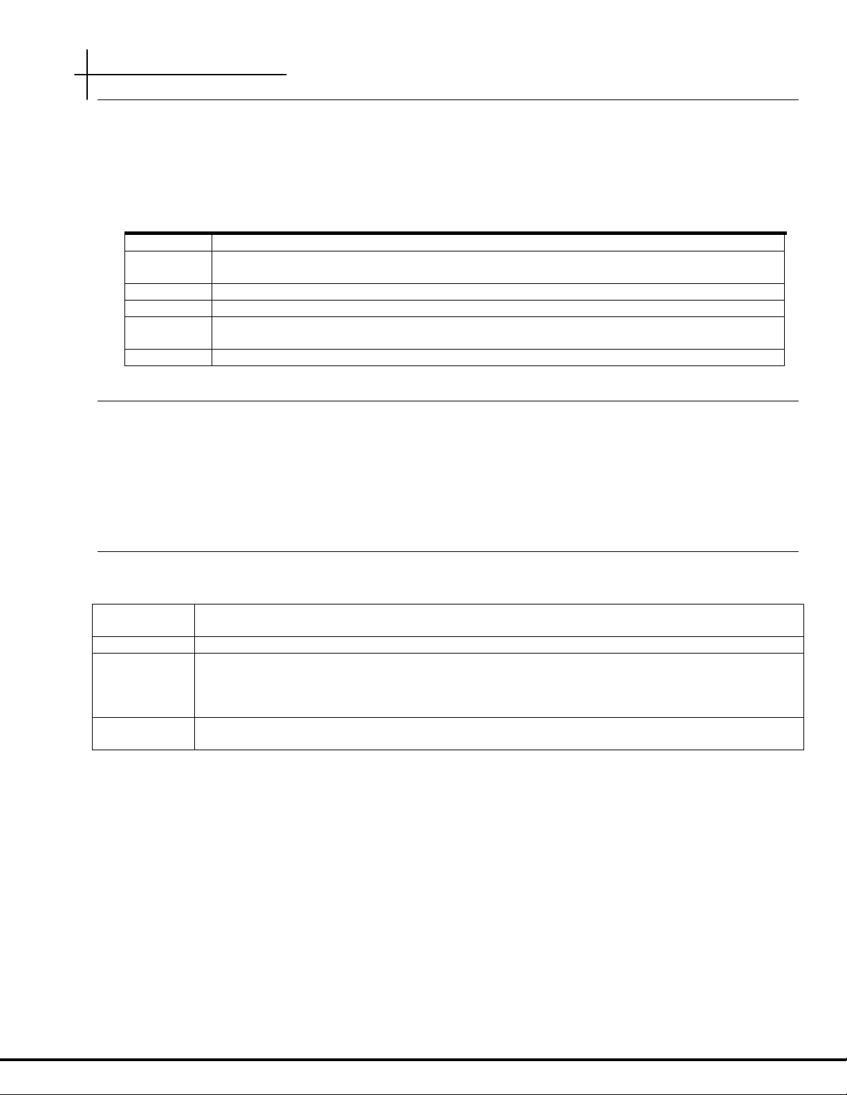
Global Commands
Commands that are available from any command context are called global commands. For example, the help
command can be used whether you are at the root command context or down a few levels in the command
hierarchy. Global commands can also be used from either the user or admin account.
Note: The default prompt is “system>”. If you set the system name using the “system name” command,
the prompt changes to the new system name.
Command Description
clear Clears the screen
exit Use this command to switch to the previous context. Note that using the exit command at
the root command context performs the same function as logout.
help Displays the help files
history Shows the history of the commands used in the current session.
logout Can be used with either the login (admin, user, RADIUS network authenticated) and at any
command level to terminate the current session
tree Shows the structure of the command tree
Command Completion
The CLI allows you to shorten commands as long as the characters are not ambiguous. While typing a command,
press the tab key to have the system complete the current command word or type (?) to have the system display
a list of available options. The options displayed vary according to the context:
• If you type a ? at a prompt, the system displays a list of all available commands.
• If you type an unambiguous command word, pressing ? displays all available subcommands or arguments. For
example, show ? (note the space before the question mark) displays a list of all show subcommands.
Style Conventions
The style conventions used in this manual distinguish various elements of the commands and facilitate the proper
interpretation of command syntax, parameters, and their use.
Keyword
Show the actual text you must enter. A keyword is found within carrots <>, followed by an input
parameter. You must type the keyword, followed by the parameter.
<ip-address>
Indicates the text is a variable where you must supply the actual value
[ ]
Square brackets delimit optional keywords or arguments. One or more of these optional
parameters can be entered on the same line. For example, the “interface wireless config”
command has 12 optional parameters of which you can choose only the parameters you want to
configure.
-
Hyphens are used to indicate remote ports on a connected WallPlate. Port numbers following
the hyphen are remote Ethernet ports or remote WLANs.
For example:
interface wireless enable <radio<1-25>(interface-id)>
where;
“radio” is a keyword and must be typed
<1-25> is a port range parameter for the wireless radio connected to the DSL line
(interface-id) is a description and is not typed
Proper command form:
interface wireless enable radio5
wifi wlan enable <wlan<1-25>-<1-16>(interface-id)>

Commands and Syntax
Motorola, Inc. 570510-001-00 rev A Page 11 of 50
where;
“wlan” is a keyword and must be typed
<1-25> is the port range for the radio connected to the DSL line
<1-16> is the port range of the WLAN on the radio
(interface-id) is a description and is not typed
Proper command form:
wifi wlan enable wlan25-1
Note that range commands can also be used. In the following example, WLANs 1, 2, 3 are enabled on all radios.
wifi wlan enable wlan(1-25)-(1-3)
This document refers to actual command syntax as little as possible. For a complete command syntax document,
please refer to the Command Reference guide for a complete list of all available commands, the proper syntax,
and usage examples. In no way does this User Guide attempt to replace or obsolete the Command Reference.
Interface Range
Multiple interfaces can be specified for a single command using port ranges. Use hyphens (-) and commas (,) to
delineate ports. Port numbers must be contained in parenthesis. Hyphens and commas can be combined in the
same expression to specify multiple, non-sequential interfaces. For example;
To enable all 25 DSL ports, type: interface dsl enable port(1-25)
To enable only selected DSL ports, type: interface dsl enable port(1,3,5,20-25)
Hyphens and commas can also be used to enable remote Ethernet ports along with DSL ports. For example;
To enable Eth1 and Eth2 on every WallPlate, type: interface remote enable port(1-25)-(1,2)
VLAN commands can also be completed using interface ranges.
To add VLAN 100 to Eth1 on every WallPlate, type: vlan membership add 100 interface port(1-25)-1

System Description
Motorola, Inc. 570510-001-00 rev A Page 12 of 50
S
S
y
y
s
s
t
t
e
e
m
m
D
D
e
e
s
s
c
c
r
r
i
i
p
p
t
t
i
i
o
o
n
n
The T3 PowerBroadband system is designed primarily for hospitality, but useful in any high density MDU (multiple
dwelling unit) such as long term healthcare or centrally wired apartments. The system is comprised of two
primary components; a 25-port Switch and a CPE device (the WallPlate). Advanced networking features such as
802.1Q VLANs and QoS can be managed throughout the system, from the 25-port switch to each port on the
WallPlate.
Adaptive Line Power
T3 PowerBroadband delivers operating power to the remote WallPlates.
MC-802 Wireless WallPlate
Line powered up to 300m (1000ft)
M2 Ethernet WallPlate
Line powered up to 600m (2000ft)
T
T
3
3
P
P
o
o
w
w
e
e
r
r
B
B
r
r
o
o
a
a
d
d
b
b
a
a
n
n
d
d
S
S
w
w
i
i
t
t
c
c
h
h
The T3 switch is installed in a centrally located phone room; where all the telephone wires converge. The T3
switch has 25 ports for downstream WallPlates, and 2 x GigE uplink ports.
T3 PowerBroadband Switch:
Physical
• 17.50"(43.8mm) x 14.25" (36mm) x 1.75" (44mm). 11.5lbs (5.2Kg)
• Operating Temperature: 0 - 50 degrees Celsius, 5% to 90% NC
• Operating Power: 300W maximum under full load, 200W typical
Interfaces
• Uplink ports
o Two 10/100/1000Mb autosensing, full duplex Ethernet ports via RJ45
• Downlink ports
o 25 VDSL UTP ports via RJ21 telco connector
Layer-2 Networking Features
• 802.1Q VLAN trunk ports
• 802.1Q PVID per port
• Port-based Isolation VLANs
• QoS, 4 queues per port, classification by IP-TOS or L2-COS bit
• IGMP, Layer 2+ routing, proxy, FastLeave
• 1024 entry MAC forwarding table
Management
• Telnet, Console, webUI, Syslog, SNMPv2c
• RADIUS authentication, Admin and User level login
• Security: L2 VLAN, IP ACL
M
M
2
2
E
E
t
t
h
h
e
e
r
r
n
n
e
e
t
t
W
W
a
a
l
l
l
l
P
P
l
l
a
a
t
t
e
e
The m2 Ethernet WallPlate has two 10/100Mb Ethernet ports, and a pass-through RJ11 phone connector. It is
installed at the end-point where Ethernet service is desired. It operates over a standard 2-wire telephone line.

System Description
Motorola, Inc. 570510-001-00 rev A Page 13 of 50
M2 Ethernet WallPlate:
Physical
• 5"(mm) x 3.5" (mm) x 1.25" (32mm)
• Operating Temperature: 0 - 40 degrees Celsius, 5% to 90% NC
• Operating Power: approximately 2W, line powered by the T3 Switch
Interfaces
• Uplink ports
o One VDSL single wire pair port via RJ11 jack
• Downlink ports
o Two 10/100Mb autosensing, full duplex Ethernet port via RJ45 jack
o One pass-through filtered phone port via RJ11 jack
Layer-2 Networking Features
• 802.1Q VLAN trunk ports
• 802.1Q PVID per port
• QoS, 2 queues per port, port based classification
Management
• Embedded Layer-1 channel for device management from T3 Switch
M
M
C
C
-
-
8
8
0
0
2
2
W
W
i
i
r
r
e
e
l
l
e
e
s
s
s
s
W
W
a
a
l
l
l
l
P
P
l
l
a
a
t
t
e
e
The MC-802 Wireless WallPlate has two 10/100Mb Ethernet ports, a pass-through RJ11 phone connector, and a
managed 802.11b/g radio. It is installed at the end-point where Ethernet and/or Wireless service is desired. It
operates over a standard 2-wire telephone line.
Features of the MC-802 802.11b/g radio:
Physical
• 6.625"(168mm) x 3.75" (95.25mm) x 1.75" (44.45). lbs (Kg)
• Operating Temperature: 0 - 40 degrees Celsius, 5% to 90% NC
• Operating Power: approximately 6W, line powered by the T3 Switch
Interfaces
• Uplink ports
o One VDSL single wire pair port via RJ11 jack
• Downlink ports
o Two 10/100Mb autosensing, full duplex Ethernet port via RJ45 jack
o One 802.11b/g radio
o One pass-through filtered phone port via RJ11 jack
Layer-2 Networking Features
• 802.1Q VLAN trunk ports
• 802.1Q PVID per port
• QoS, 4 queues per port
Management
• Embedded Layer-1 channel for device management from T3 Switch
• Layer-3 IP addresses from private pool or public pool
• All management centralized on T3 Switch

System Description
Motorola, Inc. 570510-001-00 rev A Page 14 of 50
Radio
• 802.11b/g
o Beacon frame control
o Probe request response
o Broadcast on/off per SDID
o Listen mode client support
o DSS/OFDM modulation via 2.4Ghz transmitter
o Regulatory Domain: FCC Part 15c 15.247 and ETS 300 328
• Transmit power: 20dBm transmitter
o Customer configurable: 1 – 14, max. In 1dBm increments
o Max transmit power of 20dBm depends on regulatory country
• Two integrated omni-directional antennas
o 3.2dBi
o Antenna receive diversity
• Security Protocols – (per SSID)
o Wireless Client Isolation
o WEP/WPA/WPA2 - Enterprise
o 802.1x/EAP
o EAP types: TLS, PEAPv0, TTLS
o AES, TKIP encryption
• QoS
o Wireless Multimedia (WMM) priority
o WMM power save
o Spectralink ready
• Virtual AP mode
o Concurrent BSS (16)
o Per-BSS SSID
o Per-BSS client isolation
o Per-BSS 802.1Q VLANs
o Per-BSS authentication/encryption
o Per-BSS bitrate
• Two runtime images in flash, realtime firmware upgrade
• Client state, status and statistics
o MAC address of client
o Client link rate
o Client link strength (dBm)
o Packets tx/rx
o Authentication status
o SSID
o MAC address
• WLAN state information
o Signal strength and MAC of other APs
o Tx signal strength
o Packet Tx/Rx statistics

Hardware
Motorola, Inc. 570510-001-00 rev A Page 15 of 50
H
H
a
a
r
r
d
d
w
w
a
a
r
r
e
e
M
M
o
o
d
d
e
e
l
l
N
N
u
u
m
m
b
b
e
e
r
r
s
s
a
a
n
n
d
d
D
D
e
e
s
s
c
c
r
r
i
i
p
p
t
t
i
i
o
o
n
n
The T3 PowerBroadband Switch is compatible with both the Wireless and Ethernet WallPlates. Both can be
mixed together on the same T3 PowerBroadband Switch.
Model Number Part Number Description
45225 558975-001-00 T3 PowerBroadband Switch. 2 x 10/100/1000Mb uplink Ethernet ports
and 25 x high speed DSL ports for connection to UTP wiring. Provides
broadband data and Adaptive Line Power for remote wireless
WallPlates. Supports 45010 and 45101. RoHS compliant.
45010 557925-001-00 MC-802 Wireless WallPlate. 1 x 802.11 b/g radio, 2 x Fast Ethernet, 1 x
high speed DSL port, 1 x analog POTS RJ11 port. Designed for
installation over existing RJ11 wall jack. RoHS compliant.
45101 549478-001-00 2 port m2a WallPlate. 2 x Fast Ethernet ports, 1 x high speed DSL port,
1 x analog POTs RJ11 port. Two powering options; Adaptive Line
Power from the 45125 switch, or local power adapter. Designed for
installation over existing RJ11 wall jack. RoHS compliant.
M
M
o
o
d
d
e
e
l
l
N
N
u
u
m
m
b
b
e
e
r
r
s
s
a
a
n
n
d
d
D
D
e
e
s
s
c
c
r
r
i
i
p
p
t
t
i
i
o
o
n
n
f
f
o
o
r
r
r
r
e
e
l
l
a
a
t
t
e
e
d
d
P
P
r
r
o
o
d
d
u
u
c
c
t
t
s
s
Filters are required for proper in-room installation. Installation may also use one or more of the following
additional products.
Model Number Part Number Description
65601 552689-001-00 In-line RJ11 filter, T3. RoHS compliant
65602 552309-001-00 In-line unterminated filter, T3. RoHS compliant
65003 552305-001-00 12VDC regulated power supply, US. RoHS compliant. Power supplies
used during installation for diagnostics.
65103 552306-001-00 12VDC regulated power supply, Euro. ROHS compliant. Power
supplies used during installation for diagnostics.
61299 552304-001-00 RJ11 telephone cable, 2m. RoHS compliant
 Loading...