


BR700
Table of contents
 Loading...
User Guide
Ethernet Broadband
Router
BR700

WARNING: TO PREVENT FIRE OR SHOCK HAZARD, DO NOT EXPOSE THIS PRODUCT TO RAIN OR MOISTURE. THE UNIT MUST NOT BE
EXPOSED TO DRIPPING OR SPLASHING. DO NOT PLACE OBJECTS FILLED WITH LIQUIDS, SUCH AS VASES, ON THE UNIT.
CAUTION: TO ENSURE REGULATORY COMPLIANCE, USE ONLY THE PROVIDED POWER AND INTERFACE CABLES.
CAUTION: DO NOT OPEN THE UNIT. DO NOT PERFORM ANY SERVICING OTHER THAN THAT CONTAINED IN THE INSTALLATION AND
TROUBLESHOOTING INSTRUCTIONS. REFER ALL SERVICING TO QUALIFIED SERVICE PERSONNEL.
This device must be installed and used in strict accordance with the manufacturer’s instructions as described in the user documentation that comes with the
product.
Postpone router installation until there is no risk of thunderstorm or lightning activity in the are a.
Do not overload outlets or extension cords, as this can result in a risk of fire or electric shock. Overloaded AC outlets, extension cords, frayed power cords,
damaged or cracked wire insulation, and broken plugs are dangerous. They may result in a shock or fire hazard.
Route power supply cords so that they are not likely to be walked on or pinched by items placed upon or against them. Pay particular attention to cords where
they are attached to plugs and convenience receptacles, and examine the point where they exit from the product.
Place this equipment in a location that is close enough to an electrical outlet to accommodate the length of the power cord.
Place this equipment on a stable surface.
When using this device, basic safety precautions should always be followed to reduce the risk of fire, electric shock and injury to persons, including the
following:
• Read all of the instructions {listed here and/or in the user manual} before you operate this equipment. Give particular attention to all safety precautions.
Retain the instructions for future reference.
• Comply with all warning and caution statements in the instructions. Observe all warning and caution symbols that are affixed to this equipment.
• Comply with all instructions that accompany this equipment.
• Avoid using this product during an electrical storm. There may be a risk of electric shock from lightning. For added protection for this product during a
lightning storm, or when it is left unattended and unus ed for long periods of time, unplug it from the wall outlet, and disconnect the cable system. This will
prevent damage to the product due to lightning and power surges.
• Operate this product only from the type of power source indicated on the product’s marking label. If you are not sure of the type of power supplied to your
home, consult your dealer or local power company.
• Upon completion of any service or repairs to this product, ask the service technician to perform safety checks to determine that the product is in safe
operating condition.
It is recommended that the customer install an AC surge protector in the AC outlet to which this device is connected. This is to avoid damaging the equipment by
local lightning strikes and other electrical surges.
Different types of cord sets may be used for connections to the main supply circuit. Use only a main line cord that complies with all applicable product safety
requirements of the country of use.
Installation of this product must be in accordance with national wiring codes.
Place unit to allow for easy access when disconnecting the power cord/adapter of the device from the AC wall outlet.
Wipe the unit with a clean, dry cloth. Never use cleaning fluid or similar chemicals. Do not spray cleaners directly on the unit or use forced air to remove dust.
This product was qualified under test conditions that included the use of the supplied cables between system components. To be in compliance with regulations,
the user must use these cables and install them properly. Connect the unit to a grounding type AC wall outlet using the power adapter supplied with the unit.
Do not cover the device, or block the airflow to the device with any other objects. Keep the device away from excessive heat and humidity and keep the device
free from vibration and dust.
Installation must at all times conform to local regulations.
FCC Compliance Class B Digital Device
This equipment has been tested and found to comply with the limits for a Class B digital device, pursuant to Part 15 of the FCC Rules. These limits are designed
to provide reasonable protection against harmful interference in a residential environment. This equipment generates, uses, and can radiate radio frequency
energy and, if not installed and used in accordance with the instructions, may cause harmful interference to radio communications. However, the re is no
guarantee that interference will not occur in a particular installation. If this equipment does cause harmful interfere nce to radio or television reception, which can
be determined by turning the equipment off and on, the user is encouraged to try to correct the interference by one of the following measures:
• Reorient or relocate the receiving antenna.
• Increase the separation between the equipment and receiver.
• Connect the equipment into an outlet on a circuit different from that to which the receiver is connected.
• Consult the dealer or an experienced radio/TV technician for help.
CAUTION: Changes or modifications not expressly approved by Motorola for compliance could void the user’s authority to operate the equipment.

Canadian Compliance
This Class B digital apparatus meets all requirements of the Canadian Interference Causing Equipment Regulations. Cet appareil numérique de la classe B
respects toutes les exigences du Règlement sur le matériel brouilleur du Canada.
FCC Declaration of Conformity
Motorola, Inc., Broadband Communications Sector, 101 Tournament Drive, Horsham, PA 19044, 1-215-323-1000, declares under sole responsibility that the
WR850G, WE800G, WA840G, WN825G, WPCI810G, and BR700 comply with 47 CFR Parts 2 and 15 of the FCC Rules as a Class B digital device. This
device complies with Part 15 of FCC Rules. Operation of the device is subject to the following two conditions: (1) This device may not cause harmful
interference, and (2) this device must accept any interference that may cause undesired operation.
Copyright © 2003 by Motorola, Inc.
All rights reserved. No part of this publication may be reproduced in any form or by any means or used to make any derivative work (such as
translation, transformation or adaptation) without written permission from Motorola, Inc.
Motorola reserves the right to revise this publication and to make changes in content from time to time without obligation on the part of Motorola to
provide notification of such revision or change. Motorola provides this guide without warranty of any kind, either implied or expressed, including,
but not limited to, the implied warranties of merchantability and fitness for a particular purpose. Motorola may make improvements or changes in
the product(s) described in this manual at any time.
MOTOROLA and the Stylized M Logo are registered in the US Patent & Trademark Office. Microsoft Windows screen shots are used by
permission of Microsoft Corporation. All other product or service names are the property of their respective owners. © Motorola, Inc. 2003

Contents
Section 1:Overview _______________________ 1-1
Features ................................................................................................................ 1-2
Understanding Your User Guide......................................................................... 1-3
Box Contents ........................................................................................................ 1-3
Understanding Functions .................................................................................... 1-4
Router .................................................................................................................1-4
TCP/IP.................................................................................................................1-4
Static IP Address...........................................................................................................1-4
Dynamic IP Address......................................................................................................1-4
DHCP Server ......................................................................................................1-5
Simple Home Network Diagram .......................................................................... 1-5
Router Physical Description................................................................................ 1-6
Back of Router ....................................................................................................1-6
Front of Router ....................................................................................................1-8
LED Description ..................................................................................................1-8
Section 2:Installation______________________ 2-1
Hardware Setup .................................................................................................... 2-1
Router Physical Installation.................................................................................2-1
Horizontal Installation ....................................................................................................2-1
Vertical Installation ........................................................................................................2-2
Wall Mount Installation ..................................................................................................2-2
Electrical Connection to Router...........................................................................2-6
Easy Software Setup............................................................................................ 2-6
Manual Software Setup........................................................................................ 2-6
Connection to Router ..........................................................................................2-7
Configure Your Computers.................................................................................. 2-8
Configuring Windows 98SE and ME ...................................................................2-9
Configuring Windows 2000 ...............................................................................2-11
Configuring Windows XP...................................................................................2-13
Log In................................................................................................................... 2-16
Configure Your Basic Internet Settings............................................................ 2-17
DHCP Configuration..........................................................................................2-17
PPPoE...............................................................................................................2-17
Static IP.............................................................................................................2-18
PPTP.................................................................................................................2-18
CONTENTS I

CONTENTS
Section 3:Configuration ___________________ 3-1
Using the Configuration Utility.............................................................................3-1
Log In ..................................................................................................................3-1
Navigation ...........................................................................................................3-2
Help, Restart, and Log Out .................................................................................3-2
Configuring Internet Settings...............................................................................3-3
Internet - Basic....................................................................................................3-3
Internet - Advanced.............................................................................................3-7
Internet - Network Diagnostic..............................................................................3-9
Configuring Parental Control Settings ..............................................................3-10
Parental Control - Content Policy......................................................................3-10
Parental Control - URL Log...............................................................................3-13
Configuring Networking Settings ......................................................................3-14
Networking - DHCP Server ...............................................................................3-14
Networking - DNS Proxy ...................................................................................3-17
Networking - Routing.........................................................................................3-19
Networking - DDNS...........................................................................................3-20
Networking - NAT..............................................................................................3-22
Networking - Port Trigger..................................................................................3-23
Networking - Virtual Server ...............................................................................3-25
Networking - Firewall.........................................................................................3-26
Configuring Control Panel Settings...................................................................3-27
Control Panel - Device Security ........................................................................ 3-27
Control Panel - Firmware Update......................................................................3-29
Control Panel - Configuration Data ...................................................................3-29
Control Panel - Time .........................................................................................3-30
Control Panel - UPnP........................................................................................3-31
Control Panel - Event Log.................................................................................3-31
Section 4:Troubleshooting _________________ 4-1
Contact Us ..........................................................................................................4-1
Hardware Solutions...............................................................................................4-1
My computer is experiencing difficulty in connecting to the router. ...............................4-1
My broadband modem already uses a built-in router. ...................................................4-2
Software Solutions................................................................................................4-2
I would like to test to see if my Internet connection is alive. ..........................................4-2
I cannot access the Configuration Utility for the router..................................................4-3
Section 5:Glossary _______________________ 5-1
II CONTENTS
Section 1:Overview
Congratulations on purchasing the Motorola Ethernet Broadband
Router BR700. With this router you have entered the world of
convenience and independence. Your router enables you to set up
your own private network for your PCs to: access the Internet, share
a printer, even participate in online gaming.
With a built-in firewall and Network Address Translation (NAT), your
Internet connection is robust and secure, giving you the security to
use the Internet without fear that your network might be
compromised.
Upgradeable firmware also keeps the router’s control software up-todate, so you’ll know you have the latest version. The Ethernet
Broadband Router BR700 captures the latest technology in a
package that stays current, protects your home network, and
provides you easy home network management.
Ethernet Broadband Router BR700
Your router is really several products built into one unit:
! Internet Sharing
! 4-port Full Duplex 10/100 Ethernet Switch and Router
! Firewall and NAT protection
Internet Sharing
Enables you to share your broadband Internet connection with all
of your Ethernet connected computers and devices.
SECTION 1, OVERVIEW 1-1

SECTION 1 OVERVIEW
4-port Full Duplex 10/100 Ethernet Switch and Router
Enables connection of up to 4 PCs. The routing function enables
each of your networked PCs to share files and printers as well.
Firewall and NAT Protection
Protection against Internet intruders is crucial and the built-in
Firewall will protect you. Of course, the product also supports
Virtual Private Network (VPN) connections through the firewall,
allowing you the freedom to connect when you need it.
Also supported are the NAT and MAC filtering protocols, giving
you the choice to share your Internet connection with only those
whom you designate.
Your Motorola Ethernet Broadband Router BR700 protects and
connects you by sharing your files, Internet connection, printers and
multi-player games, all in one great unit.
Features
The BR700 has the following features:
! CD-ROM based Installation Wizard to provide easy installation
! Web-based configuration of features using any web browser
! Firmware upgrade to stay current with latest specifications
! Firewall protection with NAT translation, IP and MAC address
filtering
! A built-in DHCP server to easily configure a private Local Area
Network (LAN)
! Virtual Private Network (VPN) pass-through allowing remote
connection with your corporate network
1-2 SECTION 1, OVERVIEW
OVERVIEW SECTION 1
Understanding Your User Guide
The User Guide is subdivided into the following sections:
Overview Provides a general introduction for using your
product, the type of technology used, and
recommended practices for using it.
Installation It is assumed that you will use the Installation
Wizard on the CD-ROM to setup your unit. If not,
this section provides details on getting your unit up
and running.
Once you have completed this section, your unit
will be active and ready to work.
Configuration Provides descriptive details for using the
Configuration Utility to manage your unit.
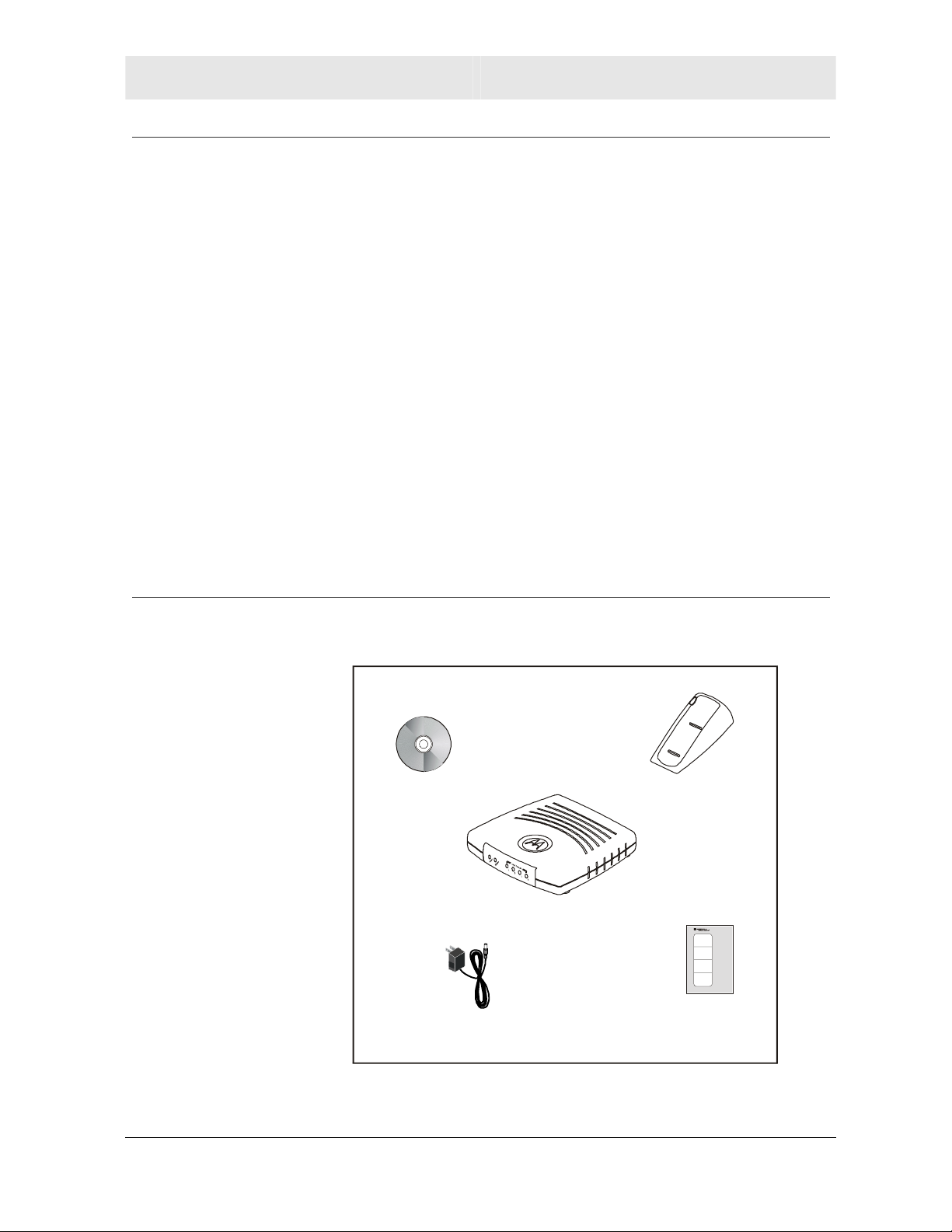
Box Contents
Glossary List of terms and acronyms
Your box contains the following:
CD-ROM
BR700
Power
Supply
Base Station Stand
Quick Start
Guide
SECTION 1, OVERVIEW 1-3

SECTION 1 OVERVIEW
Understanding Functions
The various technologies and features utilized by your router require
some explanation so you can make the correct choices when
configuring your router.
Router
Routers connect two networks together, or in your case, your home
network with the Internet (which can be thought of as a very large
network). Routers provide bandwidth security by keeping data out of
your home network where it does not belong.
The router’s Firewall inspects each packet of data as it flows through
the port before delivering it to the appropriate PC. Network Address
Translation (NAT) translates one set of IP addresses, usually private,
to another set, usually public. This is how your network remains
protected and private on the Internet.
TCP/IP
Transmission Control Protocol/Internet Protocol (TCP/IP) comprises
the backbone of the Internet. IP moves packets of data between
nodes while TCP verifies delivery from client to server. Every device
you hook up to your router identifies itself with an IP address. You
are able to assign devices on your network with either a static or
dynamically assigned IP address.
Static IP Address
A static IP address is a fixed address that is assigned manually to a
device on the network. Static IP addresses must be unique and
cannot be shared, therefore they are used in situations where the
address should never change, like print servers or PC servers.
If using your router to share an Internet connection, your Internet
Service Provider (ISP) might have assigned you a static IP address,
which you will use when configuring your router. See more
information in Configuration.
Dynamic IP Address
A dynamic IP address is a temporary IP number, dynamically or
randomly generated by a DHCP server. The address lasts only as
long as the server allots, usually in the space of a day or two. When
the IP address expires, the client is automatically reassigned a new
IP address, ensuring smooth communication.
If using your router to share an Internet connection, your ISP might
have assigned you a dynamic IP address, which you use when
configuring your router. See more information in Configuration.
1-4 SECTION 1, OVERVIEW
OVERVIEW SECTION 1
DHCP Server
A Dynamic Host Configuration Protocol (DHCP) Server assigns IP
addresses to clients connected to the router. Client is the general
term used to describe any device that connects with your unit. The
client (PC, gaming device, etc.) is automatically assigned an IP
address every time a device is added to your network, freeing you
from manually assigning IP addresses.
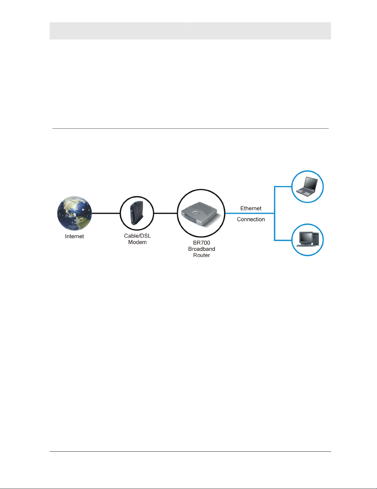
Simple Home Network Diagram
Your router serves as the centerpiece of your network, allowing you
to share files, printers, and the Internet connection. A sample Local
Area Network (LAN) is shown below:
The Internet communicates with the modem which in turn
communicates with the router. The router acts as the gateway to your
network, sending information to whichever device asks for
information, be it from requests for Internet access to file sharing to
multiplayer games. The router controls the information for your
network, intelligently routing the information to its required destination
while at the same time protecting your network from the public
domain.
SECTION 1, OVERVIEW 1-5
SECTION 1 OVERVIEW
23456
7
Router Physical Description
The following sections describe the physical characteristics of your
unit.
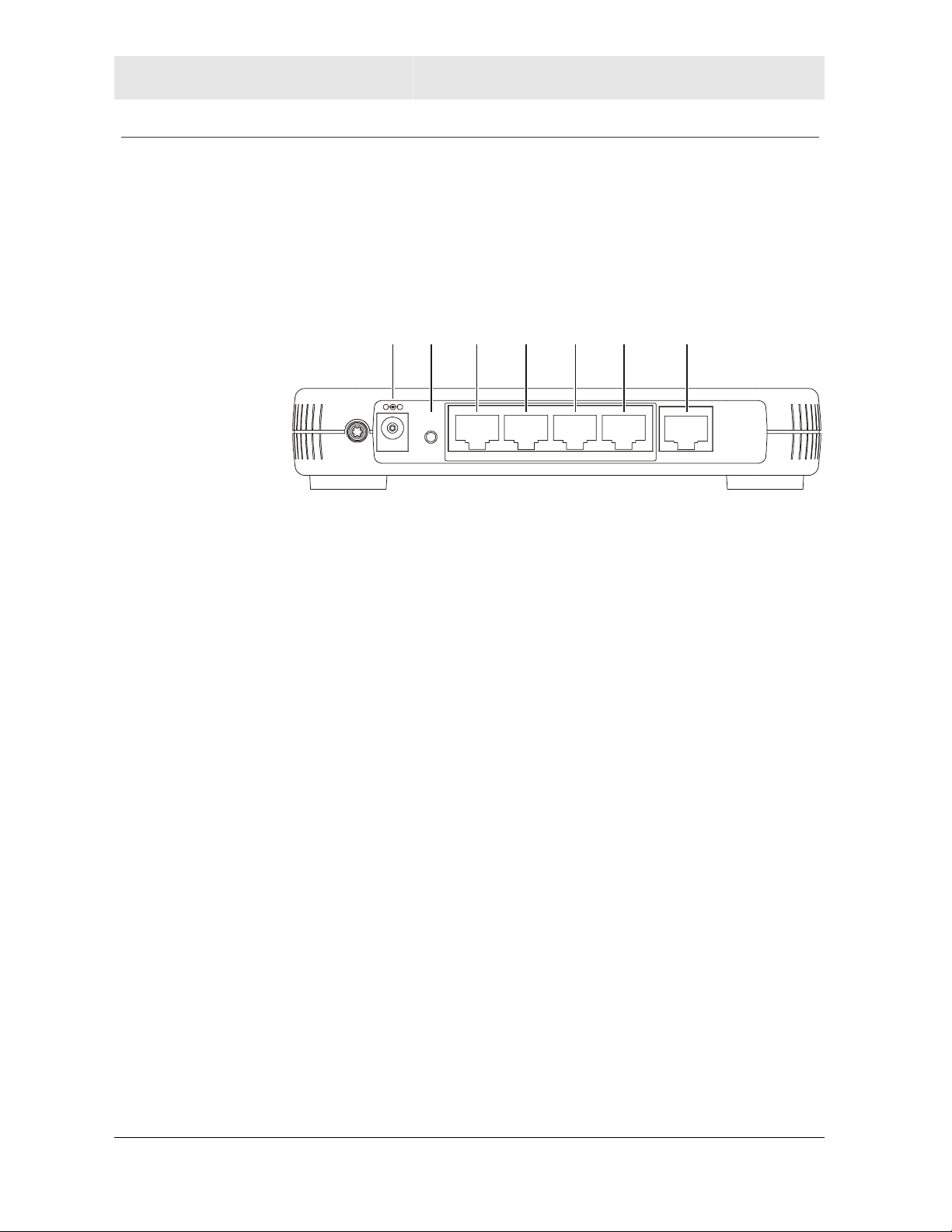
Back of Router
The following illustration shows the BR700 back panel:
1
Reset
Power
LAN 4 WAN321
Feature Description
1 Power The receptacle where you plug in the power
adapter.
2 Reset
Button
A dual-function button. It either resets your unit
or resets the unit to the default login settings.
If the router is experiencing trouble connecting
to the Internet, briefly press and release the
Reset button to reset the router. This retains the
router’s configuration information.
To reset the unit to the factory defaults, press
and hold the Reset button for more than 5
seconds.
This clears the router’s user settings, including
User ID, Password, IP Address, and Subnet
mask. Refer to Section3:Configuration for
re-configuring the router.
1-6 SECTION 1, OVERVIEW

OVERVIEW SECTION 1
Feature Description
3-6 LAN
Ports 1-4
These four ports can connect your LAN with
Ethernet cables. This enables communication
among clients, such as PCs or print servers, on
the network. The LAN ports support either
10-BASE-T or 100-BASE-T transmission
speeds as well as straight-through and
crossover Ethernet cables.
Any of these four ports can also serve as an
uplink port to other network devices, enabling
you to extend your network.
7 WAN Connect your modem to your router using this
port with your supplied Ethernet cable. This is
the only port you can use for this procedure.
This enables your router to access the Internet.
The port supports 10/100 Mbps as well as
straight-through and crossover Ethernet cables.
SECTION 1, OVERVIEW 1-7
SECTION 1 OVERVIEW
Front of Router
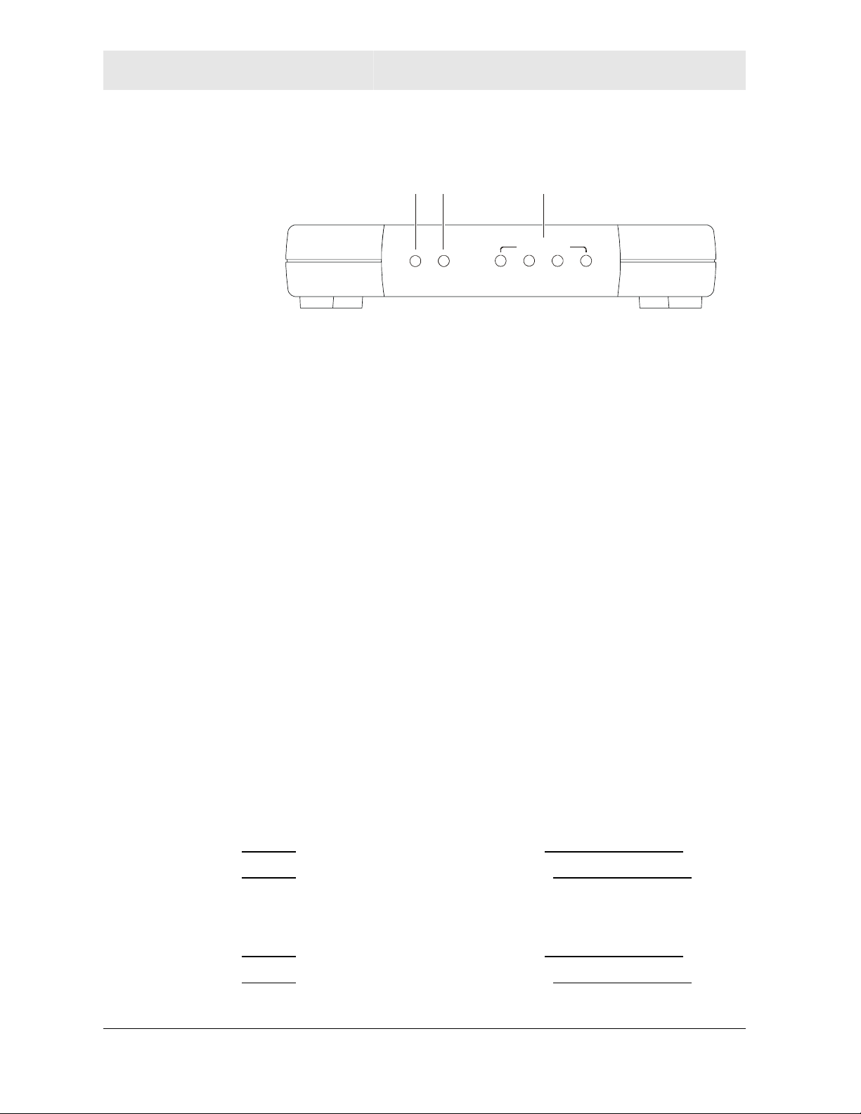
The following illustration shows the BR700 front panel:
12 3
Local Network
m
r
e
e
w
o
P
The LEDs of the router indicate its operational status.
LED Description
The underlined items indicate activity on the network.
LED Condition Color Status
d
o
M
2
1
4
3
1. Power ON
Blinking
Blinking/OFF
Green
Green
Red
The device is powered on and operating normally.
Firmware update is in progress.
The power LED turns RED as soon as the reset
button is depressed. If the reset button is held down
for more than 5 seconds, the LED starts to blink
and the router’s default user name, password,
private LAN IP address, and private subnet mask
address will be restored. The LED then turns off
until the reset button is released. The power LED
keeps blinking RED if the firmware is corrupted,
indicating the firmware needs to be restored.
2. Modem OFF
None
No external Ethernet device has been attached and
detected. The Ethernet link is down.
ON
Red
The WAN interface has been disabled by the
firmware.
Blinking
Red
The WAN connection has lost IP connectivity with
its default gateway even though the Ethernet link is
still up. Or the WAN connection repair procedure is
still in progress.
Amber
ON/Blinking
10BaseT link detected/active traffic present.
ON/Blinking
3. LAN (x4) OFF
None
100BaseT link detected/active traffic present.
No external Ethernet device has been attached and
Green
detected. The Ethernet link is down.
ON/Blinking
ON/Blinking
Green
10BaseT link detected/active traffic present.
100BaseT link detected/active traffic present.
Amber
1-8 SECTION 1, OVERVIEW
Section 2:Installation
To get your network up and running:
! Setup your hardware.
! Insert the CD-ROM for Product Setup. Follow the prompts.
If you prefer to setup the router’s software manually, refer to the
Manual Software Setup found later in this section.
The following sections provide detailed instructions for completing
these tasks.
Hardware Setup
Hardware setup includes:
! Physical Installation: where you physically place your unit.
! Electrical Connection: how to connect the power cord.
Router Physical Installation
You can install the router in various physical orientations –
horizontally, vertically, or hung on the wall. Your own needs
determine the best placement.
Horizontal Installation
1 Place the router in the desired location and follow the procedures
below for connecting and configuring the unit.
SECTION 2, INSTALLATION 2-1
SECTION 2 INSTALLATION
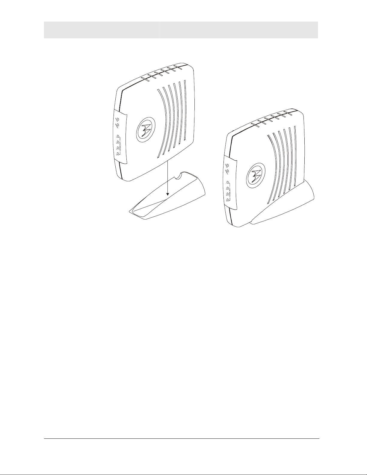
Vertical Installation
1 To use the router in a vertical position, insert the router into the
supplied base. The router’s foot slides snugly into a notch in the
base to keep the unit stable.
2 Follow the installation procedures for connecting and configuring
the unit.
Wall Mount Installation
If you mount the router on the wall, you must:
! Locate the unit as specified by the local or national codes
governing residential or business communications services.
! Follow all local standards for installing a network interface
unit/network interface device (NIU/NID).
If possible, mount the router to concrete, masonry, a wooden stud, or
other very solid wall material. Use anchors if necessary; for example
if you must mount the unit on drywall.
2-2 SECTION 2, INSTALLATION
INSTALLATION SECTION 2
To mount your router on the wall:
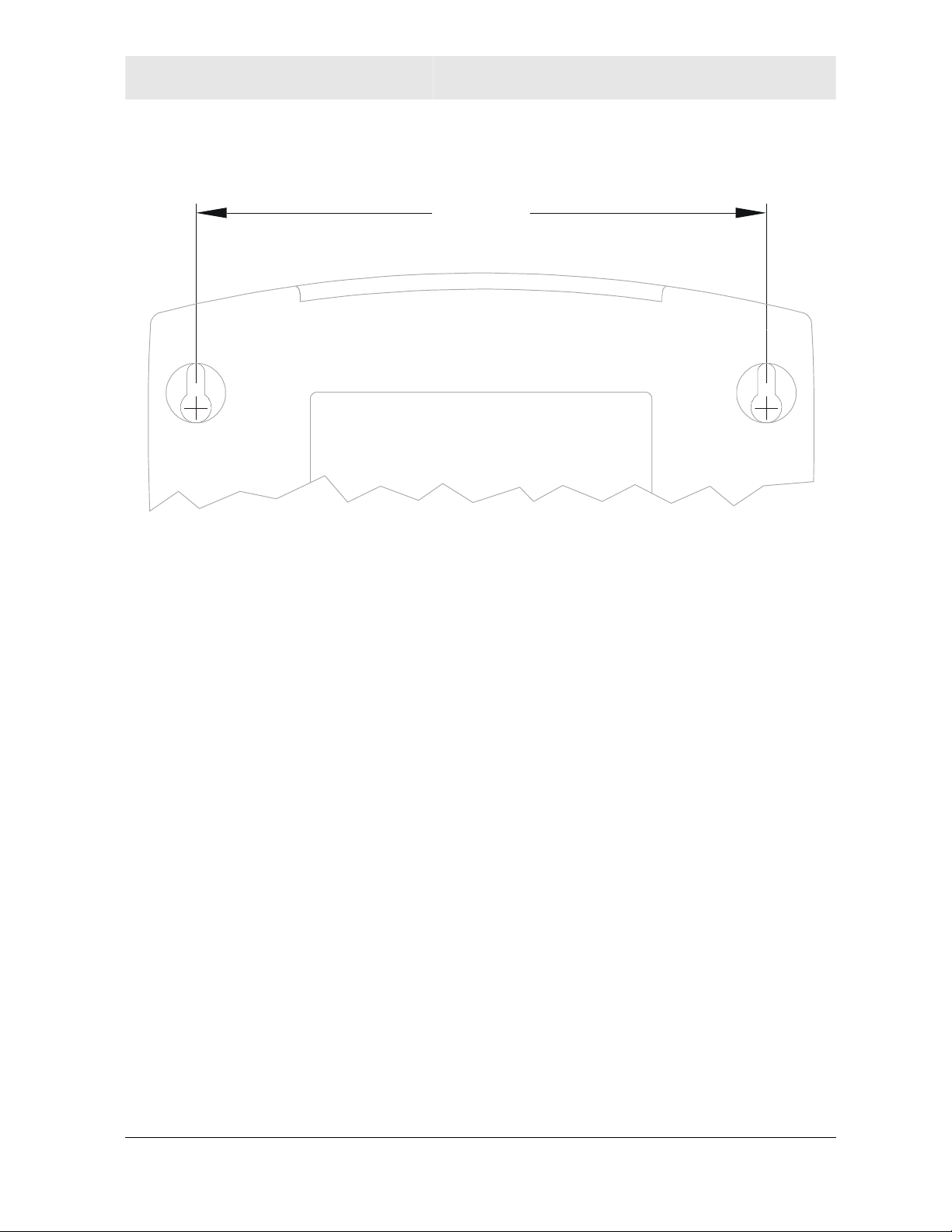
1 Print the Wall Mounting Template.
5.1”
[129.5mm]
The illustration is drawn at a one-to-one scale, which means that
when printed, it provides the exact dimensions required to mount
the unit.
SECTION 2, INSTALLATION 2-3
SECTION 2 INSTALLATION
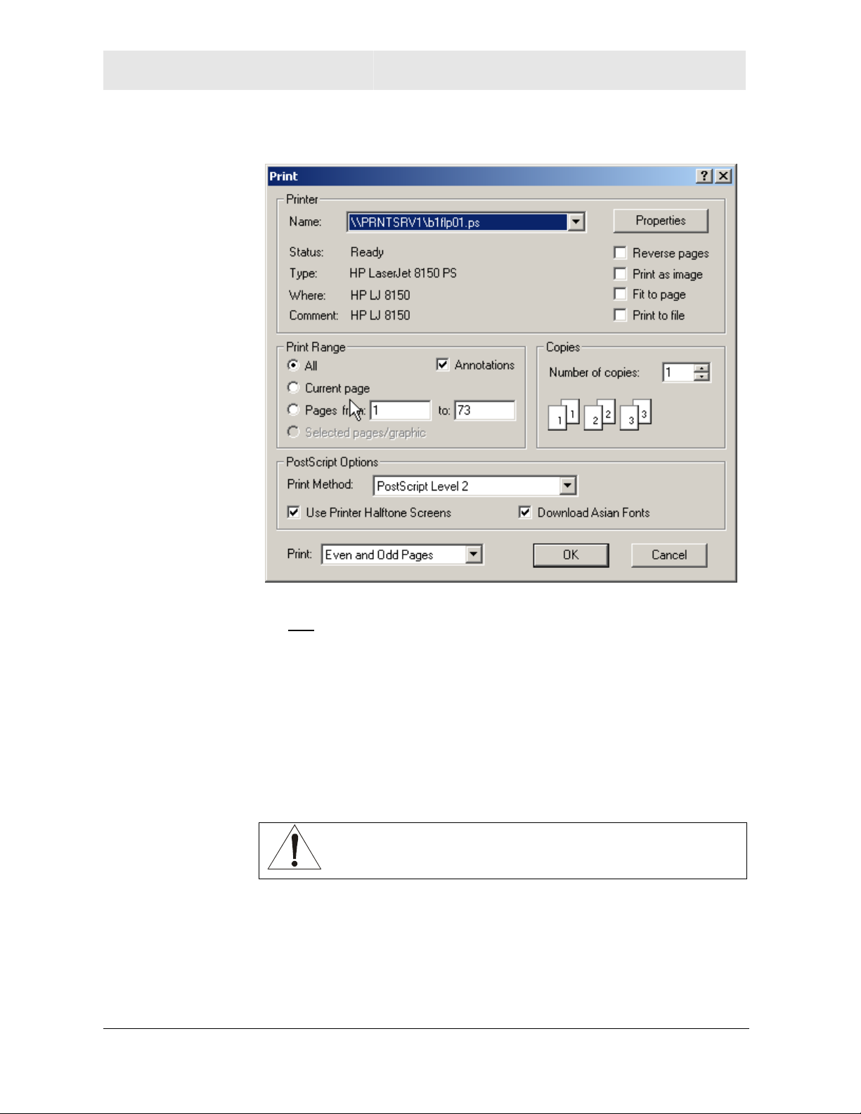
2 Click the Print icon or choose Print from the File menu to display
the Print dialog box:
Be sure you print the template at 100% scale and that Fit to page is
not
checked in the Print dialog box.
3 Click OK.
4 Measure the printed template with a ruler to ensure that it is the
correct size.
5 Use a center punch to mark the center of the holes on the wall.
6 On the wall, locate the marks for the mounting holes you just
made.
WARNING!
Before drilling holes, check the structure for potential
damage to water, gas, or electric lines.
7 Drill the holes to a depth of at least 3.8 cm (1½ inches).
8 If necessary, seat an anchor in each hole. Use M5 x 38 mm
(#10-16 x 11/2 inch) screws with a flat underside and maximum
screw head diameter of 10.5 mm to mount the router.
2-4 SECTION 2, INSTALLATION
INSTALLATION SECTION 2
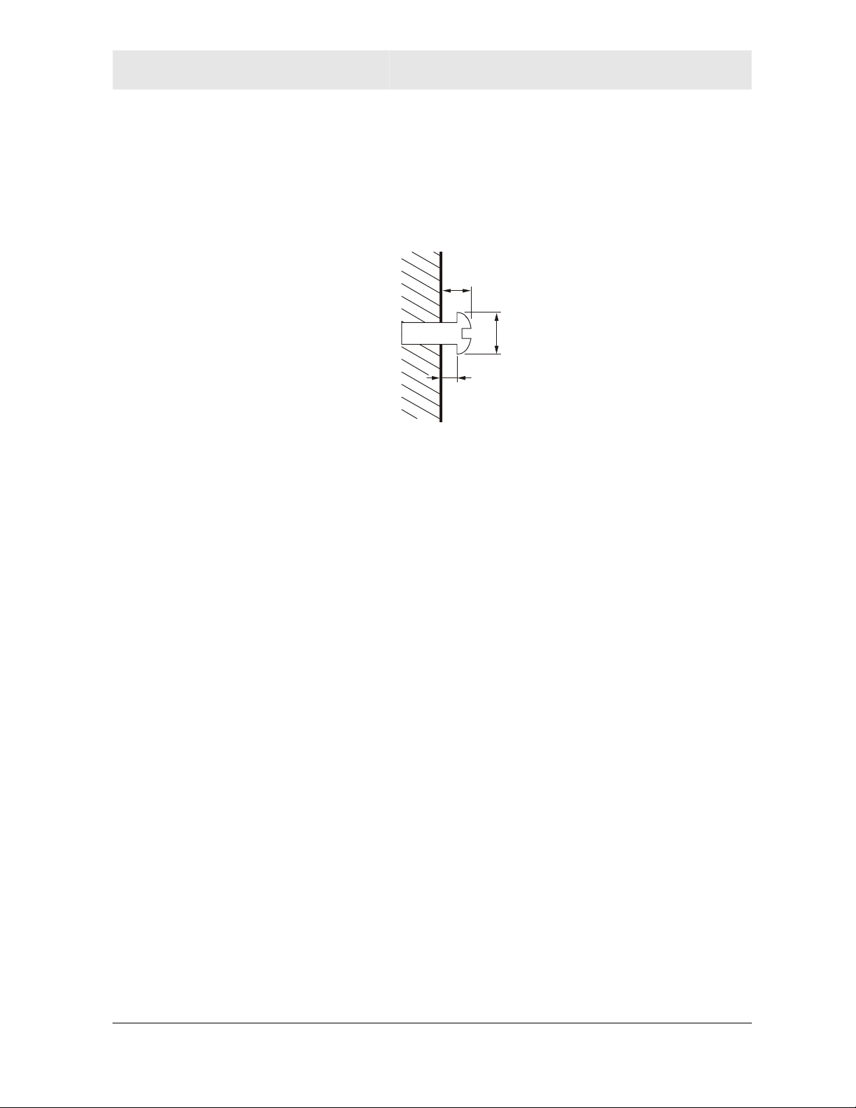
9 Using a screwdriver, turn each screw until part of it protrudes
from the wall, as shown:
! There must be 4.0 mm (.16 inches) between the wall and the
underside of the screw head.
! The maximum distance from the wall to the top of the screw
head is 7.6 mm (.3 in).
7.6 mm (.3 inches)
maximum
10.5 mm (.4 inches)
maximum
4.0 mm
10 Remove the two plastic feet, nearest to the LED panel, from the
bottom of the router to uncover the keyholes.
11 Place the router so the keyholes are above the mounting screws.
12 Slide the router down until it stops against the top of the keyhole
opening.
13 Follow the installation procedures for connecting and configuring
the unit.
SECTION 2, INSTALLATION 2-5
SECTION 2 INSTALLATION
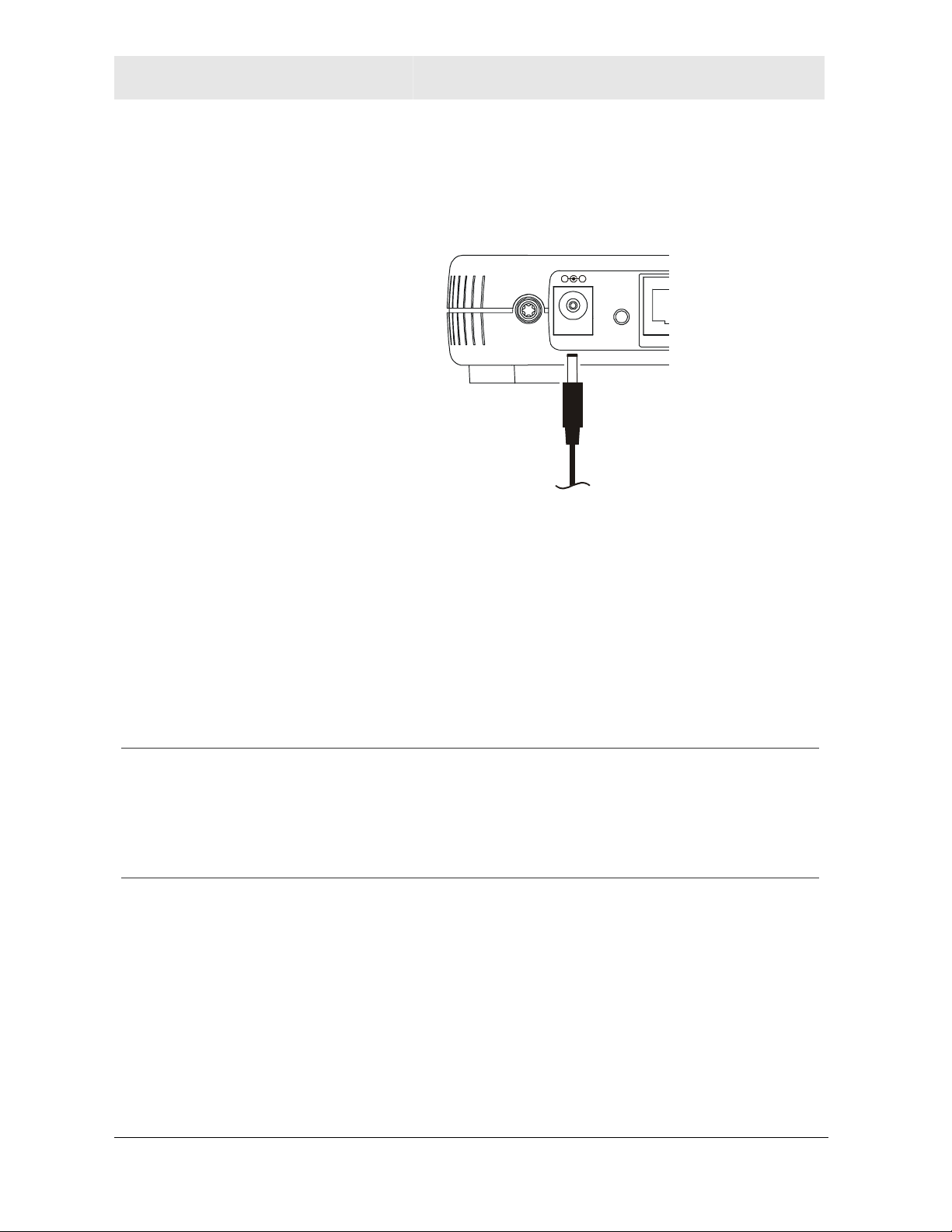
Electrical Connection to Router
Your router does not have an On/Off power switch and therefore will
only be powered on by plugging in the power adapter:
Reset
1 Connect the power adapter to the router’s Power port, found on
2 Then plug the power adapter into a grounded and surge
Easy Software Setup
Run the Installation Wizard program from the supplied CD-ROM to
quickly setup your network. Once your network is up and running,
refer to Section 3:Configuration for advanced configuration.
Power
To power
supply
LAN
the back of the unit.
protected power outlet.
! The Power LED on the front panel lights green when
connected properly.
Manual Software Setup
If you’d prefer to manually setup your network, use this section to
configure it. This section details the physical connection of the router
to your network as well as the configuration needed by your PC.
To set up your network:
! Physically connect and power on the router
! Configure your PCs
If you don’t want to use the Installation Wizard from the CD-ROM,
follow the instructions below. For advanced configurations, refer to
Section 3:Configuration.
2-6 SECTION 2, INSTALLATION
INSTALLATION SECTION 2
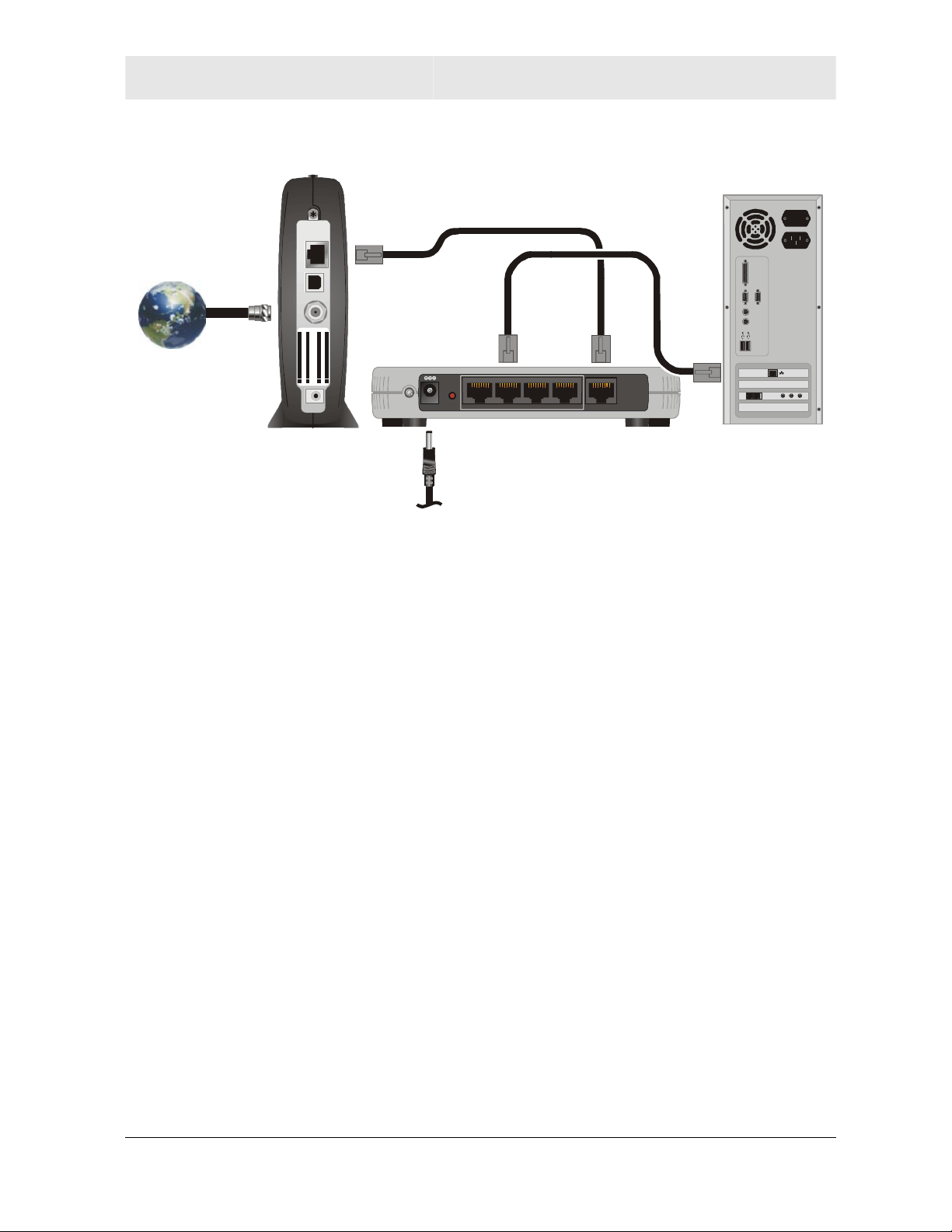
A
Connection to Router
ETHERNET
USB
CABLE
USB CPE MAC ID:A BDCEF012345
S/N: PPPPMMYJJJSSSSSCA
HFC MAC ID: ABCDEF012345
CUSTOMER S/N:BCDFGHJKLMNP
BBCCCC
Reset
LAN 4 WAN321
+12VDC
Power
When connecting your PC to the router, your PC must be installed
first with an Ethernet adapter.
You need two Ethernet cables for this procedure, one cable to connect the
router to the modem and one cable to connect a PC to the router.
1 A. If you have been running broadband to a single computer
before, unplug the Ethernet cable (that runs between your
modem and PC) from the back of your PC and plug it into the port
labeled WAN on the back of your router.
B. If you have not been running broadband to a single computer,
take one end of an Ethernet cable and plug it into the WAN port.
The WAN port is the only port that works for your connection from
the modem to the router.
2 Take the other end of the same cable and plug it into your cable
or DSL modem. You have now connected the router to the
modem.
3 To connect the PC to the router, use a different Ethernet cable
and plug it into your Ethernet port on your PC.
4 Use the other end of the same cable and plug it into one of the
LAN ports on your router. You have now connected your PC to
the router.
5 To connect more devices, repeat steps 4 and 5.
6 To configure the router, refer to Section 3: Configuration.
SECTION 2, INSTALLATION 2-7

SECTION 2 INSTALLATION
You have now completed the hardware installation. The next section,
Configure Your Computers, steps you through the various
configuration options needed for your PCs.
Configure Your Computers
Each computer that is going to be part of your network needs to “talk”
to the router. To do this, you have to configure each PC’s network
setting to automatically obtain an IP address. This section includes
information on configuring computers with the following operating
systems:
! Windows 98SE
! Windows ME
! Windows 2000
! Windows XP
Determine the operating system for each computer you are including
in your network and follow the steps to configure the network settings
for that PC.
2-8 SECTION 2, INSTALLATION
INSTALLATION SECTION 2
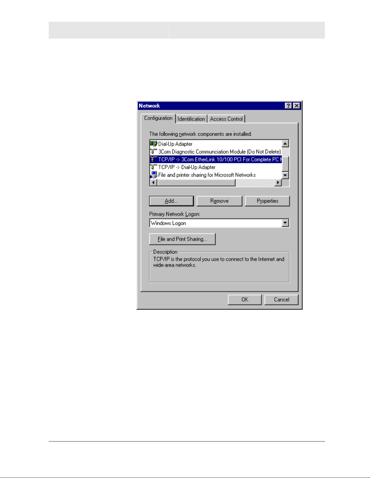
Configuring Windows 98SE and ME
1 Click Start.
2 Select Settings > Control Panel.
3 Double-click Network. The Network window is displayed:
4 On the configuration tab, select the TCP/IP line the for the
appropriate Ethernet adapter. There might be multiple adapters
installed – choose only the one that is configured for your
adapter. In the example above, a 3Com Ethernet adapter card is
installed and is the appropriate choice for this example.
SECTION 2, INSTALLATION 2-9
SECTION 2 INSTALLATION
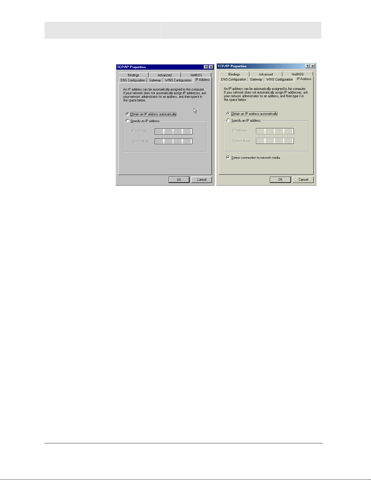
5 Click Properties. The TCP/IP Properties window is displayed:
Windows 98SE Windows ME
6 Click the IP Address tab.
7 Select Obtain an IP address automatically.
8 Click OK.
9 Click the Gateway tab and check to make sure that the Installed
Gateway field is blank.
10 Click OK twice. Windows might ask for the Windows installation
disk. First check to see if the installation files are installed at
c:\windows\options\cabs. Otherwise, install your Windows CD
and follow the prompts.
11 Restart your computer to save your settings.
2-10 SECTION 2, INSTALLATION
INSTALLATION SECTION 2
Configuring Windows 2000
1 Click Start.
2 Select Settings.
3 Select Control Panel. Double-click Network and Dial-Up
Connections. Double-click Local Area Connection.
4 Click the Properties button.
SECTION 2, INSTALLATION 2-11
Loading...