


3000 SERIES
DIRECT VENT GAS FIREPLACE
INSTALLATION AND OPERATING INSTRUCTIONS
WARNING
If the information in these instructions are not followed exactly, a fire or explosion may result causing property damage, personal injury or loss of life.
∙Do not store or use gasoline or other flammable vapors and liquids in the vicinity of this or any other appliance.
WHAT TO DO IF YOU SMELL GAS
∙Do not try to light any appliance.
∙Do not touch any electrical switch.
∙Do not use any phone in your building.
∙Immediately call your gas supplier from a neighbor’s phone. Follow the gas supplier’s instructions.
∙If you cannot reach your gas supplier, call the fire department.
∙Installation and service must be performed by a qualified installer, service agency or the gas supplier.
This appliance may be installed in an aftermarket, permanently located, manufactured (mobile home, where not prohibited by local codes.
This appliance is only for use with the type of gas indicated on the rating plate. This appliance is not convertible for use with other gases, unless a certified kit is used.
For Residential Use-Meets All HUD Requirements For Manufactured Housing Installations
DUE TO HIGH TEMPERATURES, THE APPLIANCE SHOULD BE LOCATED OUT OF TRAFFIC AND AWAY FROM FURNITURE AND DRAPERIES.
CHILDREN AND ADULTS SHOULD BE ALERTED TO THE HAZARDS OF HIGH SURFACE TEMPERATURE AND SHOULD STAY AWAY TO AVOID BURNS OR CLOTHING IGNITION.
YOUNG CHILDERN SHOULD BE SUPERVISED WHEN THEY ARE IN THE SAME ROOM AS THE APPLIANCE.
CLOTHING OR OTHER FLAMMABLE MATERIAL SHOULD NOT BE PLACED ON OR NEAR THE APPLIANCE.
KEEP THE ROOM AREA CLEAR AND FREE FROM COMBUSTIBLE MATERIALS, GASOLINE, AND OTHER FLAMMABLE VAPORS AND LIQUIDS.
∙ READ BEFORE INSTALLING OR OPERATING AND SAVE THESE INSTRUCTIONS ∙


TABLE OF CONTENTS |
|
IMPORTANT SAFETY INFORMATION: ................................................................................................................ |
2 |
PRODUCT SPECIFICATIONS: .................................................................................................................................. |
3 |
HIGH ALTITUDE INSTALLATIONS................................................................................................................................... |
3 |
LISTING & CODE APPROVAL: ................................................................................................................................ |
3 |
PRE-INSTALLATION INFORMATION: .................................................................................................................. |
4 |
BEFORE YOU START: ..................................................................................................................................................... |
4 |
FIREPLACE LOCATION:................................................................................................................................................... |
4 |
WALL AND CEILING CLEARANCE REQUIREMENTS: ...................................................................................................... |
6 |
COMBUSTIBLE CLEARANCES: ........................................................................................................................................ |
6 |
MANTEL CLEARANCES: ................................................................................................................................................. |
7 |
FLOOR CLEARANCES: .................................................................................................................................................... |
7 |
MINIMUM VENT CLEARANCES TO COMBUSTIBLE MATERIALS: ................................................................................... |
7 |
FRAMING DIMENSIONS: ................................................................................................................................................. |
8 |
FINISHING MATERIAL: ................................................................................................................................................... |
9 |
VENT INSTALLATION:............................................................................................................................................. |
10 |
POSITIONING THE FIREPLACE: ..................................................................................................................................... |
10 |
VENTING CONFIGURATION: ......................................................................................................................................... |
10 |
INSTALLING VENT COMPONENTS ..................................................................................................................... |
12 |
BEFORE YOU START: ................................................................................................................................................... |
12 |
PIPING INSTALLATIONS:............................................................................................................................................... |
12 |
VENT TERMINATION: ................................................................................................................................................... |
15 |
GAS LINE AND ELECTRICAL ................................................................................................................................ |
19 |
GAS LINE INSTALLATION:............................................................................................................................................ |
19 |
ELECTRICAL WIRING: .................................................................................................................................................. |
20 |
FINAL INSTALLATION............................................................................................................................................. |
26 |
WALL FINISHING:......................................................................................................................................................... |
26 |
FINISHING THE FIREPLACE FLUSH WITH A WALL: ........................................................................................................ |
26 |
INSTALLATION COMPONENTS ON FIREPLACE: ............................................................................................................ |
26 |
GLASS REMOVAL: ........................................................................................................................................................ |
27 |
ROCK WOOL PLACEMENT:............................................................................................................................................ |
28 |
LOG PLACEMENT:......................................................................................................................................................... |
29 |
OPERATING INSTRUCTIONS................................................................................................................................. |
30 |
BEFORE LIGHTING THE FIREPLACE:............................................................................................................................. |
30 |
DURING LIGHTING THE FIREPLACE: ............................................................................................................................ |
30 |
MAINTENANCE .......................................................................................................................................................... |
33 |
BURNER & CONTROL COMPARTMENT: ....................................................................................................................... |
33 |
PILOT FLAME: .............................................................................................................................................................. |
33 |
BURNER FLAME: .......................................................................................................................................................... |
33 |
VENT SYSTEM:............................................................................................................................................................. |
34 |
GLASS DOOR:............................................................................................................................................................... |
34 |
LOGS............................................................................................................................................................................. |
34 |
PARTS LIST / ILLUSTRATION ............................................................................................................................... |
35 |
TROUBLESHOOTING ............................................................................................................................................... |
38 |
STANDING PILOT IGNITION:......................................................................................................................................... |
38 |
ELECTRONIC PILOT IGNITION: ..................................................................................................................................... |
40 |
1

IMPORTANT SAFETY INFORMATION
IMPORTANT SAFETY INFORMATION:
INSTALLER: Please leave these instructions with the owner.
OWNER: Please read and retains these instructions for future reference.
IMPORTANT: Read these instructions carefully before installing or trying to operate this appliance.
∙DO NOT use this appliance if any part has been under water. Immediately call a qualified service technician to inspect the appliance and to replace any part of the control system and any gas control, which has been under water.
∙The appliance and its individual shutoff valve must be disconnected from the gas supply piping system during any pressure testing of that system at test pressures in excess of 1/2 psig (3.5 kPa).
∙The appliance must be isolated from the gas supply piping system by closing its individual manual shutoff valve during any pressure testing of the gas supply piping system at test pressures equal to or less than 1/2 psig (3.5 kPa).
∙Installation and repair should be done by a qualified service person.
∙This appliance MUST BE installed on a metal or wood plate extending the full width and depth of the unit if the unit is to be installed on carpet, vinyl tile or any combustible other than wood.
∙CARBON MONOXIDE POISONING: Early signs of carbon monoxide poisoning are similar to the flu with headaches, dizziness and/or nausea. If you have these signs, obtain fresh air immediately. Have the appliance serviced, as it may not be operating properly.
∙To prevent malfunction and/or sooting, this appliance should be inspected before use and at least annually by a professional service person. More frequent cleaning may be required due to excessive lint from carpeting, bedding materials, etc. It is imperative that control compartments, burners and circulating air passageways of the appliance be kept clean. Refer to MAINTENANCE section found in this manual.
∙This gas fireplace is a vented gas appliance. DO NOT burn wood or other material in this appliance.
∙This appliance and vent assembly MUST be vented directly to the outside. This appliance MUST NEVER be connected to a chimney flue(s) servicing a separate solid-fuel burning appliance or any other appliances.
∙This appliance MUST use one of the vent systems described in the venting system of this manual. NO other vent systems or components may be used.
∙Venting terminals MUST NOT be recessed into a wall or siding
∙Inspect the external vent cap on a regular basis to make sure that no debris is interfering with the airflow.
∙Provide adequate clearances around air openings and adequate accessibility clearance for servicing and operation. NEVER obstruct front opening of the appliance.
∙DO NOT OPERATE the appliance with the glass door removed, cracked, or broken. Replacement of the glass door should be done by a licensed or qualified person. DO NOT strike or slam the door. The glass door assembly should only be replaced as a complete unit supplied by manufacturer. NO substitute materials should be used.
∙DO NOT use abrasive cleaners on the glass door assembly. Do not clean glass door when it is hot.
∙Any safety screen or guard (i.e. glass door) removed for servicing an appliance should be replaced prior to operating the appliance.
∙The installation must conform with local codes, or in the absence of local codes, with the National Fuel Gas Code, ANSI Z223.1 (in the United States) or with the current installation code CAN/CGA - B149 (in Canada).
∙This unit complies with ANSI Z21.88-98, CGA 2.32-98.
∙During manufacturing, fabricating, and shipping, various components of this appliance are treated with certain oils, film, or bonding agents. These chemicals are not harmful but may produce annoying smoke and smells as they are burned off during the initial operation of the appliance; possibly causing headaches or eye and lung irritation. This is a normal and temporary occurrence. The initial break-in operation should last 2-3 hours with the burner at the highest setting. Provide maximum ventilation by opening windows and doors to allow odors to dissipate with continued use.
2

PRODUCT SPECIFICATIONS/LISTING & CODE APPROVAL
PRODUCT SPECIFICATIONS:
|
|
|
|
Gas Pressure (Inches W.C.) |
||
Models Number |
Gas Type |
Control Type |
Max Btu |
Max |
Min |
Manifold |
320DV4136NV |
Natural Gas |
Milli-volt |
26000 |
10.5 |
4.0 |
3.5 |
320DV4136PV |
Propane/LPG |
Milli-volt |
26000 |
13.0 |
11.0 |
10.0 |
320DV4742NV |
Natural Gas |
Milli-volt |
28000 |
10.5 |
4.0 |
3.5 |
320DV4742PV |
Propane/LPG |
Milli-volt |
28000 |
13.0 |
11.0 |
10.0 |
320DV4136NE |
Natural Gas |
Electronic Ign |
26000 |
10.5 |
4.0 |
3.5 |
320DV4136PE |
Propane/LPG |
Electronic Ign |
26000 |
13.0 |
11.0 |
10.0 |
320DV4742NE |
Natural Gas |
Electronic Ign |
28000 |
10.5 |
4.0 |
3.5 |
320DV4742PE |
Propane/LPG |
Electronic Ign |
28000 |
13.0 |
11.0 |
10.0 |
High Altitude Installations
Gas rate shown above is for altitudes up to 2000 ft. When installing this fireplace at an elevation above 2000 ft, it may be necessary to decrease the input rating by changing the existing burner orifice to a smaller size. Input should be reduced four percent (4%) for each 1000 ft above sea level, unless the heating value of the gas has been reduced. Consult your local dealer or gas authority for assistance in determining the proper orifice at your location.
LISTING & CODE APPROVAL:
The above models have been tested and certified by the applicable laboratories to the standards listed below.
MODEL |
LAB. |
TYPE |
CERTIFICATION STANDARD |
320DV4136 Series |
CSA |
Vented Gas Fireplace Heaters |
ANSI Z21.88-1998∙CSA 2.33-M98 |
320DV4742 Series |
CSA |
Vented Gas Fireplace Heaters |
ANSI Z21.88-1998∙CSA 2.33-M98 |
In addition, this appliance may be installed in an aftermarket, permanently located, manufactured (mobile home, where not prohibited by local codes. This appliance is only for use with the type of gas indicated on the rating plate. This appliance is not convertible for use with other gases, unless a certified kit is used.
3

PRE-INSTALLATION INFORMATION
PRE-INSTALLATION INFORMATION:
Before You Start:
Read this homeowner manual thoroughly and follow all instructions carefully. Inspect all contents for shipping damage and immediately inform your dealer if any damage is found. Do not install any unit with damaged, incomplete, or substitute parts.
Contents:
∙Fireplace – Firebox and Burner system
∙Fiber Ceramic Logs Set
∙Canopy/Hood
∙Lava Rock
∙Rock Wool
∙Restrictor Kit
∙Deflector Shield (to be used with Horizontal Termination P/N 985)
Items Required For Installations: |
|
Tools: |
Building Supplies: |
Phillips Screwdriver |
Framing Materials |
Hammer |
Wall Finishing Materials |
Saw and / or saber saw |
Caulking Material (Noncombustible) |
Level |
Fireplace Surround Material (Noncombustible) |
Measuring Tape |
Piping Complying with Local Codes |
Electric Drill and Bits |
Tee Joint |
Pliers |
Pipe Sealant Approved for use with Propane/LPG |
Square |
(Resistant to Sulfur Compounds) |
Pipe Wrench |
|
Fireplace Location: |
|
Plan for the installation of your appliance. This includes determining where the unit is to be installed, the vent configuration to be used, framing and finishing details, and whether any optional accessories (i.e. blower, wall switch, or remote control) are desired. Consult your local building code agency to ensure compliance with local codes, including permits and inspections.
The following factors should be taken into consideration:
∙Clearance to side-wall, ceiling, woodwork, and windows. Minimum clearances to combustibles must be maintained.
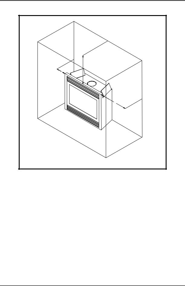
∙This fireplace may be installed along a wall, across a corner, or use an exterior chase. Refer to Figure 2 for suggested locations.
∙Location should be out of high traffic areas and away from furniture and draperies due to heat from appliance.
∙Never obstruct the front opening of the fireplace.
∙Do not install in the vicinity where gasoline or other flammable liquids may be stored.
∙Vent pipe routing. Refer to Venting section found in this manual for allowable venting configurations.
∙These units can be installed in a bedroom. Refer to National Fuel Gas Code ANSII Z233.1/NFPA 54 - (current edition), the Uniform Mechanical Code - (current edition), and Local Building Codes for specific installation requirements.
4

PRE-INSTALLATION INFORMATION
Figure 1: Fireplace Dimensions
2 |
Figure 2: Fireplace Locations and Minimum Clearances Requirements
5
PRE-INSTALLATION INFORMATION
31” Min
2” Min
2” Min
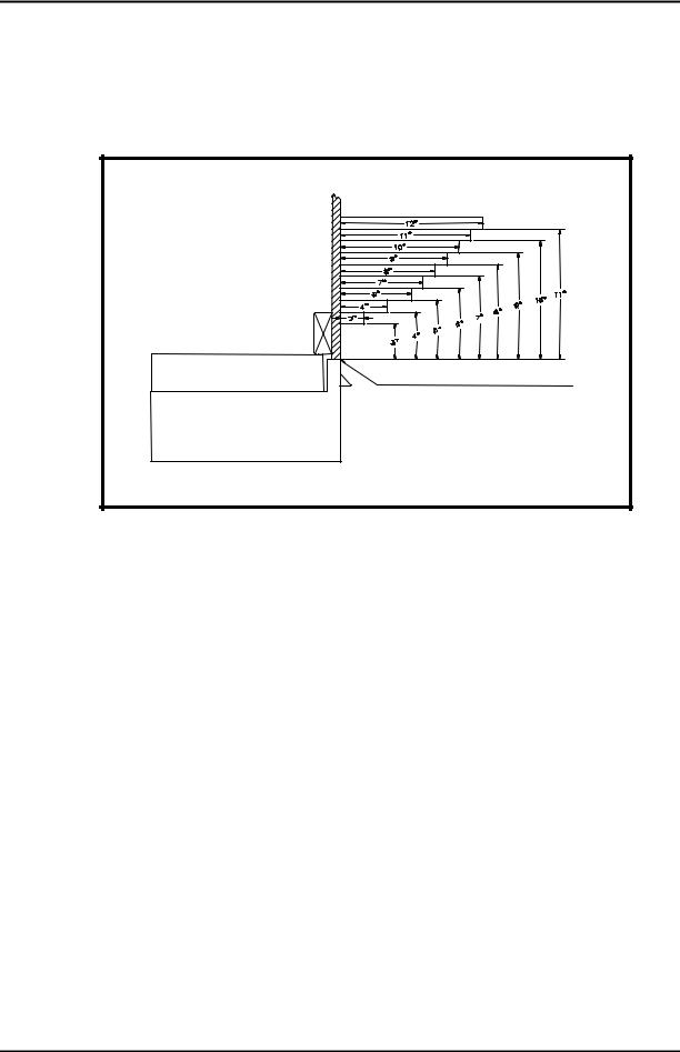
Figure 3: Wall & Ceiling Minimum Clearances
Wall and Ceiling Clearance Requirements:
Ensure that minimum clearance shown in Figures 3 is maintained. Left and right clearances are determined when facing the front of the appliance. Follow these instructions carefully to ensure safe installation. Failure to follow these requirements may create a fire hazard.
Side-wall Clearance: The clearance from the front edge of the appliance to any combustible wall should not be less than 2” on both the left and right side.
Ceiling Clearance: The ceiling must be at least 31” from the top of the front of the fireplace (65.5” from the bottom of the appliance). Refer to Figure 3.
Back-wall Clearance: The appliance may be placed against a combustible back wall. NOTE: There are 1/4” ribs/spacers on the outer shell of the unit to maintain minimum clearance of the outer shell to combustibles.
Combustible Clearances:
The appliance is a zero clearance fireplace with ribs/spacers defining the minimum space to the sheet metal outer shell. Combustibles may be placed up against these spacers. Do NOT place combustibles (i.e., insulation, wood, etc.) closer than allowed by the spacers or a fire hazard may exist. The ribs/spacers for the sides and rear of the appliance are 1/4” and the top spacers are 3 1/4”. On the front top edge in front of the top framing spacers, a combustible wall (or drywall) may be brought up to the top edge of the unit. Refer to Figure 4.
6
PRE-INSTALLATION INFORMATION
Mantel Clearances:
A hood/canopy comes with every appliance. If a combustible mantel is installed, it must meet the clearance requirements detailed in Figure 4.
Combustible wall or drywall to top front edge of unit
Figure 4: Mantel Clearance
Floor Clearances:
The fireplace may be installed on a flat, hard combustible surface (i.e. flat wood, plywood, or particleboard). Be sure that the fireplace rests on a solid continuous floor of platform with appropriate framing support. Do NOT install appliance directly on carpeting, vinyl, or other soft floor covering. If the fireplace is to be installed on carpeting or tile, or on any combustible material other than wood flooring, the fireplace should be installed on a metal or wood panel that extends the full width and depth of the fireplace.
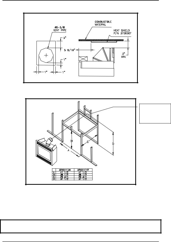
Minimum Vent Clearances to Combustible Materials:
The minimum clearances to combustibles for vent pipe require 3 inches at the top and 1 inch at the sides and bottom for horizontal sections of the vent system. Refer to the figure below. For wall or ceiling firestops and vertical sections of vent pipe a 1-inch minimum clearance all around the pipe must be maintained.
On some installation, if the distance between the first elbow and combustible material is three (3) inches, a heat shield is required. This part can be obtained from Monessen or constructed out of steel material to maintain halfinch (1/2”) air gap between the pipe and combustible material. The size of the part must be at least 12” wide by 12” long. Refer to figure below.
7
PRE-INSTALLATION INFORMATION
Figure 5: Combustible Clearances for Vent Pipe
Framing Dimensions:
Shows Center of 10”X 10” Vent Framing holes for Horizontal Venting
Figure 6: Minimum Framing Dimensions
Firebox framing can be built before or after the appliance is set in place. Framing should be positioned to accommodate wall covering and fireplace facing mantel. Figure 6 shows a typical framing of this appliance. Refer to Figure 1 for firebox dimensions. All minimum clearances must be maintained in framing the appliance. The framing headers may rest on the top of the framing spacers.
CAUTION
Measure fireplace dimensions and verify framing methods & wall covering details before framing construction begins.
8
PRE-INSTALLATION INFORMATION
Finishing Material:
NOTE
Any remote wiring (i.e. remote control, wall switch, and optional fan) must be done prior to final finishing to avoid costly reconstruction.
WARNING
Never obstruct or modify the air inlet or outlet grills (louvers) in any manner as it may create a fire hazard.
Only noncombustible materials (i.e. brick, tile, slate, steel, or other materials with a UL fire rating of Zero) may be used to cover the black surface of the appliance. A 300°F minimum adhesive may be used to attach facing materials to the black surface. If joints between the finished wall and the fireplace surround are sealed, a 300° F minimum sealant material (General Electric RTV103 or equivalent) must be used. Refer to Figure 7.
Combustible |
Noncombustible materials only |
|
are permitted to cover black face |
||
Material |
||
of unit |
||
|
||
High temperature sealant |
|
|
permitted at these joints |
|
|
|
Inlet/Outlet Grills (Louvers) |
|
|
Do not cover/modify |
Figure 7: Finishing Material
9
VENT INSTALLATION
VENT INSTALLATION:
Positioning The Fireplace:
NOTE
The fireplace must be installed giving full consideration to the clearance and height requirements identified in this manual.
1.Bend out the six (6) nailing flanges located on the sides and top of the fireplace
2.Slide the firebox into prepared framing or position fireplace in its final position and frame later. Be sure fireplace is rested on a flat surface.
3.Level the fireplace by checking the top of unit. Shim side-to-side and front-to-back as necessary.
4.Anchor nailing flanges of the fireplace to the side-framing members using 8d nails or other suitable fasteners.
Venting Configuration:
These models are approved to use Simpson-Duravent 4 X 6-5/8 Direct Vent Pipe Components and Monessen Hearth System termination kits. No other venting systems or components may be used. See PARTS LIST / ILLUSTRATIONS section for a list of approved vent components.
WARNING
Any common venting of this gas appliance with other gas appliances is not allowed. Do not connect this appliance to a chimney flue servicing a separate solid fuel-burning appliance.
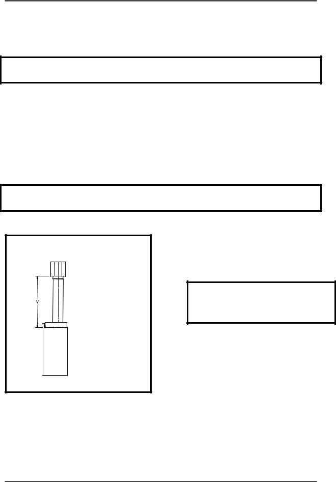
Venting Vertical Straight Up (No Elbow):
Dim |
Min |
Max |
V |
6 feet |
40 feet |
NOTE
Air Restrictor Kit is recommended for vertical runs of 10 feet or more to improve flame appearance. This kit can be found in the homeowner manual packet assembly.
Figure 8: Vertical Venting - Straight Up
10
VENT INSTALLATION
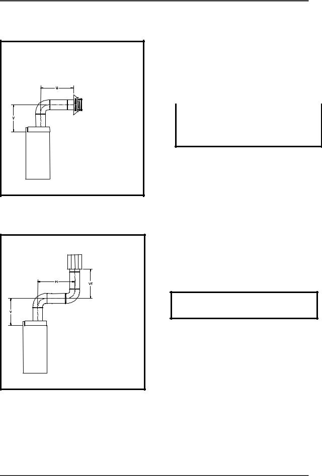
Horizontal Venting with One (1) Elbow:
|
V, Vertical |
H, Horizontal |
|
|
Elbow (5 inches) |
30 inches Max |
|
|
Elbow (5 inches) |
30 inches Corner Max |
|
|
1 foot Min |
5 feet Max |
|
|
2 feet Min |
10 feet Max |
|
|
3 feet Min |
15 feet Max |
|
|
4 feet Min |
20 feet Max |
|
NOTE
If a 90° Elbow is first attached to the unit, the maximum horizontal run, H, is 30 inches straight out, and 30 inches at a corner installation.
Figure 9: Horizontal Venting with One (1) Elbow
Vertical Venting with Two (2) Elbows:
V, Vertical |
H, Horizontal |
1 foot Min |
5 feet Max |
2 feet Min |
10 feet Max |
3 feet Min |
15 feet Max |
4 feet Min |
20 feet Max |
NOTE
V1 dimension must satisfy this condition:
V + H + V1 < 40 feet.
Figure 10: Vertical Venting with Two (2) Elbows
11

VENT INSTALLATION
Horizontal Venting with Three (3) Elbows:
V, Vertical |
H, Horizontal |
1 foot Min |
5 feet Max |
2 feet Min |
10 feet Max |
3 feet Min |
15 feet Max |
4 feet Min |
20 feet Max |
NOTE
H1 and V1 dimension must satisfy these two conditions:
H + H1 < 20 feet V + H + V1 < 40 feet.
Figure 11: Horizontal Venting with Three (3) Elbows
INSTALLING VENT COMPONENTS
Before You Start:
Plan your installation. Set unit in place and survey how best to vent the unit. Select the appropriate pipe for the installation. Read this manual and the manual with the termination cap thoroughly before installing unit or vent system. After vent configuration has been decided, begin attaching pipe to unit.
Piping Installations:
1.Remove the cover plate on top of the fireplace using a Philips screwdriver.
2.Attached the first piece piping (elbow or straight pipe) to the pipe connector located inside the fireplace. All vent pipes will lock into place by sliding the sections together. Nest the 4 indentations on the female end of one pipe into the slots of the pipe connector and then twist the pipe together (Refer to the instructions that comes with termination for more detailed explanation).
3.Continue to add vent components. Be certain that each section is locked properly.
4.Where necessary add support brackets. Refer to the figure below. Horizontal runs must be supported every 3 feet using wall straps (P/N 988). Vertical runs must be supported every 8 feet using wall straps (P/N 988). Slip wall straps loosely on to pipe. Attach straps to framing members using nails or screws. Tighten nut/bolt to secure pipe.
12
 Loading...