


 Loading...
11A-0-1
ENGINE
F8QT SERIES
CONTENTS
GENERAL INFORMATION . . . . . . . . . . . . . . . . . . . . . . . . . . . . . . . 11A-0-3 1. SPECIFICATIONS . . . . . . . . . . . . . . . . . . . . . . . . . . . . . . . . . . . 11A-1-1 SERVICE SPECIFICATIONS . . . . . . . . . . . . . . . . . . . . . . . . 11A-1-1 TORQUE SPECIFICATIONS . . . . . . . . . . . . . . . . . . . . . . . . 11A-1-5 FORM-IN-PLACE GASKET . . . . . . . . . . . . . . . . . . . . . . . . . 11A-1-8 2. SPECIAL TOOLS . . . . . . . . . . . . . . . . . . . . . . . . . . . . . . . . . . . . 11A-2-1
3. CRANKSHAFT PULLEY . . . . . . . . . . . . . . . . . . . . . . . . . . . . . . 11A-3-1 4. TIMING BELT . . . . . . . . . . . . . . . . . . . . . . . . . . . . . . . . . . . . . . . 11A-4-1 5. WATER PUMP . . . . . . . . . . . . . . . . . . . . . . . . . . . . . . . . . . . . . . 11A-5-1 6. THERMOSTAT . . . . . . . . . . . . . . . . . . . . . . . . . . . . . . . . . . . . . . 11A-6-1 7. WATER HOSES AND PIPES . . . . . . . . . . . . . . . . . . . . . . . . . . 11A-7-1 8. ENGINE COOLANT TEMPERATURE SENSOR . . . . . . . . . 11A-8-1 9. GLOW PLUGS . . . . . . . . . . . . . . . . . . . . . . . . . . . . . . . . . . . . . . 11A-9-1 10. TURBOCHARGER . . . . . . . . . . . . . . . . . . . . . . . . . . . . . . . . . . . 11A-10-1 11. INTAKE AND EXHAUST MANIFOLDS . . . . . . . . . . . . . . . . . 11A-11-1 12. ROCKER COVER AND CYLINDER HEAD . . . . . . . . . . . . . . 11A-12-1 13. CAMSHAFT, INTAKE AND EXHAUST VALVES . . . . . . . . . 11A-13-1 14. VACUUM PUMP . . . . . . . . . . . . . . . . . . . . . . . . . . . . . . . . . . . . . 11A-14-1 15. OIL COOLER AND OIL FILTER . . . . . . . . . . . . . . . . . . . . . . . 11A-15-1 16. OIL PAN, OIL PUMP AND OIL JETS . . . . . . . . . . . . . . . . . . . 11A-16-1
17. INTERMEDIATE SHAFT AND INTERMEDIATE
SHAFT BEARINGS . . . . . . . . . . . . . . . . . . . . . . . . . . . . . . . . . . 11A-17-1 18. FUEL INJECTION NOZZLE . . . . . . . . . . . . . . . . . . . . . . . . . . . 11A-18-1 19. FUEL INJECTION PUMP . . . . . . . . . . . . . . . . . . . . . . . . . . . . . 11A-19-1 20. PISTONS AND CONNECTING RODS . . . . . . . . . . . . . . . . . . 11A-20-1 21. PISTONS AND PISTON PINS . . . . . . . . . . . . . . . . . . . . . . . . . 11A-21-1 22. FLYWHEEL . . . . . . . . . . . . . . . . . . . . . . . . . . . . . . . . . . . . . . . . . 11A-22-1 23. CRANKSHAFT AND CYLINDER BLOCK . . . . . . . . . . . . . . . 11A-23-1
|
|
|
E Mitsubishi Motors Corporation |
July 1996 |
PWEE9602 |

11A-0-2
NOTES
E Mitsubishi Motors Corporation |
July 1996 |
PWEE9602 |
F8QT ENGINE - General Information |
11A-0-3 |
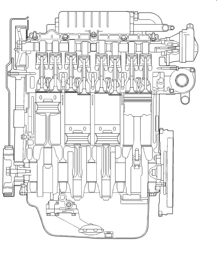
GENERAL INFORMATION
SECTIONAL VIEW OF ENGINE
REN0137
E Mitsubishi Motors Corporation |
July 1996 |
PWEE9602 |

11A-0-4 |
F8QT ENGINE - General Information |
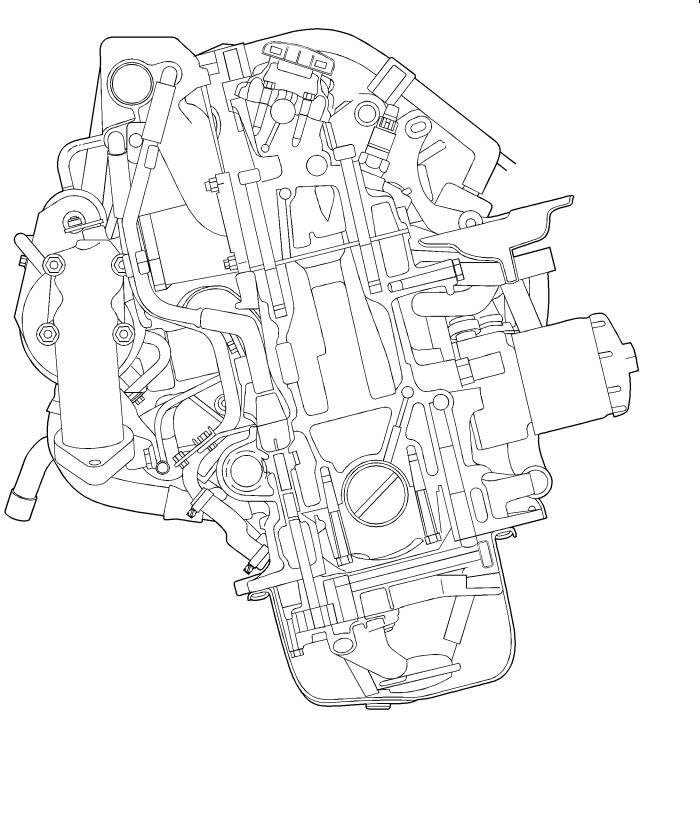
SECTIONAL VIEW OF ENGINE
REN0138
E Mitsubishi Motors Corporation |
July 1996 |
PWEE9602 |
F8QT ENGINE - General Information |
11A-0-5 |
SECTIONAL VIEW OF ENGINE
REN0139
E Mitsubishi Motors Corporation |
July 1996 |
PWEE9602 |

11A-0-6 |
F8QT ENGINE - General Information |
|
|
|
|
Description |
|
Specifications |
|
|
|
Type |
|
F8QT diesel engine |
|
|
|
Number and arrangement of cylinders |
4 in-line |
|
|
|
|
Combustion chamber |
|
Swirl chamber |
|
|
|
Total displacement |
|
1870 cm3 |
Cylinder bore ´ stroke |
|
80 ´ 93 mm |
|
|
|
Compression ratio |
|
21 |
|
|
|
Valve mechanism |
|
Single overhead camshaft |
|
|
|
Number of valves |
Intake |
4 |
|
|
|
|
Exhaust |
4 |
|
|
|
Valve timing |
Intake opening |
0_ BTDC |
|
|
|
|
Intake closing |
18_ ABDC |
|
|
|
|
Exhaust opening |
41_ BBDC |
|
|
|
|
Exhaust closing |
0_ ATDC |
|
|
|
Turbocharger |
|
Exhaust gas turbocharger |
|
|
|
Intercooler (charge cooling) |
|
Air-cooled |
|
|
|
Fuel injection pump |
|
Electric with immobilizer |
|
|
|
E Mitsubishi Motors Corporation |
July 1996 |
PWEE9602 |

|
|
|
F8QT ENGINE - Specifications |
11A-1-1 |
|||
1. SPECIFICATIONS |
|
|
|
|
|
||
SERVICE SPECIFICATIONS |
|
|
|
|
|||
|
|
|
|
|
|
|
|
Item |
|
|
|
|
Standard |
Limit |
|
|
|
|
|
|
|
|
|
Cylinder head |
|
|
|
|
|
|
|
|
|
|
|
|
|
||
Flatness of cylinder head surface mm |
|
|
0.05 |
- |
|||
|
|
|
|
|
|
|
|
Cylinder head gasket |
|
|
|
|
|
|
|
|
|
|
|
|
|
|
|
Gasket thickness |
|
Projecting |
height |
of |
Number of holes; 2 |
1.4 |
- |
mm |
|
piston - 0.073 |
|
|
|
|
|
|
|
|
|
|
|
|
|
|
|
Projecting |
height |
of |
Number of holes; 1 |
1.5 |
- |
|
|
piston 0.073 - 0.206 |
|
|
|
||
|
|
|
|
|
|
|
|
|
|
Projecting |
height |
of |
Number of holes; 3 |
1.6 |
- |
|
|
piston 0.206 - |
|
|
|
|
|
|
|
|
|
|
|
|
|
Cylinder block |
|
|
|
|
|
|
|
|
|
|
|
|
|
|
|
Cylinder diameter mm |
|
|
|
Class A |
80.006 - 80.024 |
- |
|
|
|
|
|
|
|
|
|
|
|
|
|
|
Class B |
80.256 - 80.274 |
- |
|
|
|
|
|
|
|
|
Pistons |
|
|
|
|
|
|
|
|
|
|
|
|
|
||
Piston-to-cylinder clearance mm |
|
|
|
0.021 - 0.055 |
- |
||
|
|
|
|
|
|
|
|
Standard, class A |
|
|
|
|
79.971 - 79.985 |
- |
|
|
|
|
|
|
|
|
|
Standard, class B |
|
|
|
|
80.221 - 80.235 |
- |
|
|
|
|
|
|
|
|
|
Piston rings |
|
|
|
|
|
|
|
|
|
|
|
|
|
|
|
Height mm |
|
|
|
Top |
2.5 |
- |
|
|
|
|
|
|
|
|
|
|
|
|
|
|
Bottom |
2 |
- |
|
|
|
|
|
|
|
|
|
|
|
|
|
Oil |
3 |
- |
|
|
|
|
|
|||
Axial clearance in piston groove mm |
|
Top |
0.030 - 0.065 |
- |
|||
|
|
|
|
|
|
|
|
|
|
|
|
|
Bottom |
0.030 - 0.065 |
- |
|
|
|
|
|
|
|
|
|
|
|
|
|
Oil |
0.030 - 0.065 |
- |
|
|
|
|
|
|
||
Fitted gap (in cylinder) mm |
|
|
Top |
0.30 - 0.40 |
- |
||
|
|
|
|
|
|
|
|
|
|
|
|
|
Bottom |
0.25 - 0.40 |
- |
|
|
|
|
|
|
|
|
|
|
|
|
|
Oil |
0.25 - 0.50 |
- |
|
|
|
|
|
|
|
|
Piston pin |
|
|
|
|
|
|
|
|
|
|
|
|
|
|
|
Diameter mm |
|
|
|
|
26 |
- |
|
|
|
|
|
|
|
|
|
E Mitsubishi Motors Corporation |
July 1996 |
PWEE9602 |

11A-1-2 |
|
F8QT ENGINE - Specifications |
|
|||
|
|
|
|
|
|
|
Item |
|
|
|
Standard |
Limit |
|
|
|
|
|
|
|
|
Camshaft |
|
|
|
|
|
|
|
|
|
|
|
|
|
Cam height |
|
|
Intake |
8.5 |
- |
|
|
|
|
|
|
|
|
|
|
|
|
Exhaust |
10.34 |
- |
|
|
|
|
|
|
|
Camshaft end play mm |
|
|
|
0.048 - 0.133 |
- |
|
|
|
|
|
|
|
|
Radial clearance mm |
|
|
|
0.050 - 0.150 |
- |
|
|
|
|
|
|
|
|
Valves |
|
|
|
|
|
|
|
|
|
|
|
|
|
Valves clearance |
|
Checking |
|
Intake |
0.15 - 0.25 |
- |
mm |
|
|
|
|
|
|
|
|
|
Exhaust |
0.35 - 0.45 |
- |
|
|
|
|
|
|||
|
|
|
|
|
|
|
|
|
Adjusting |
|
Intake |
0.2 |
- |
|
|
|
|
|
|
|
|
|
|
|
Exhaust |
0.4 |
- |
|
|
|
|
|
|
|
Valve diameter mm |
|
|
Intake |
36.22 |
- |
|
|
|
|
|
|
|
|
|
|
|
|
Exhaust |
31.62 |
- |
|
|
|
|
|
|
|
Valve seat angle |
|
|
Intake |
60_ |
- |
|
|
|
|
|
|
|
|
|
|
|
|
Exhaust |
45_ |
- |
|
|
|
|
|
|
|
Valve seat width mm |
|
|
Intake |
1.8 ± 0.2 |
- |
|
|
|
|
|
|
|
|
|
|
|
|
Exhaust |
1.8 |
- |
|
|
|
|
|
|
|
Valve springs |
|
|
|
|
|
|
|
|
|
|
|
|
|
Length mm |
|
|
Loading 0 N |
43.9 |
- |
|
|
|
|
|
|
|
|
|
|
|
|
Loading 250 N |
36.8 |
- |
|
|
|
|
|
|
|
|
|
|
|
Loading 612 N |
26.4 |
- |
|
|
|
|
|
|
|
Tappets |
|
|
|
|
|
|
|
|
|
|
|
||
Diameter (tolerance) mm |
|
|
35 |
- |
||
|
|
|
|
|
|
|
Height mm |
|
|
|
26.3 |
- |
|
|
|
|
|
|
||
Clearance in cylinder block mm |
|
|
0.025 - 0.075 |
- |
||
|
|
|
|
|
|
|
Valve guides |
|
|
|
|
|
|
|
|
|
|
|
|
|
Inside diameter mm |
|
|
|
8 |
- |
|
|
|
|
|
|
|
|
Outside diameter mm |
|
|
Standard |
13 |
- |
|
|
|
|
|
(no grooves) |
|
|
|
|
|
|
|
|
|
|
|
|
|
Oversize 1 |
13.3 |
- |
|
|
|
|
(two grooves) |
|
|
|
|
|
|
|
|
|
Tappet pads |
|
|
|
|
|
|
|
|
|
||||
Thickness (increasing by increments of 0.05) mm |
2.50 - 3.70 |
- |
||||
|
|
|
|
|
|
|
E Mitsubishi Motors Corporation |
July 1996 |
PWEE9602 |

F8QT ENGINE - Specifications |
11A-1-3 |
||
|
|
|
|
Item |
|
Standard |
Limit |
|
|
|
|
Intermediate shaft |
|
|
|
|
|
|
|
Inner bearing mm |
|
39.5 |
- |
|
|
|
|
Outer bearing mm |
|
40.5 |
- |
|
|
|
|
End play mm |
|
0.07 - 0.15 |
- |
|
|
|
|
Crankshaft |
|
|
|
|
|
|
|
End play mm |
|
0.07 - 0.23 |
- |
|
|
|
|
Thrust washer thickness mm |
|
2.30 - 2.50 |
- |
|
|
|
|
Radial clearance (main bearings) mm |
|
0.04 - 0.07 |
- |
|
|
|
|
Main bearing journals |
|
|
|
|
|
|
|
Ovality mm |
|
- |
0.0025 |
|
|
|
|
Taper mm |
|
- |
0.005 |
|
|
|
|
Diameter mm |
Standard (blue) |
54.785 - 54.805 |
- |
|
|
|
|
|
Standard (red) |
54.795 - 54.805 |
- |
|
|
|
|
|
Undersize 1 |
54.550 - 54.560 |
- |
|
|
|
|
Big-end bearing journals |
|
|
|
|
|
|
|
Ovality mm |
|
- |
0.0025 |
|
|
|
|
Taper mm |
|
- |
0.005 |
|
|
|
|
Diameter mm |
Standard |
48.00 - 48.02 |
- |
|
|
|
|
|
Undersize 1 |
47.75 - 47.77 |
- |
|
|
|
|
Bearing recess width mm |
|
20.25 - 20.95 |
- |
|
|
|
|
Relative difference mm |
|
- |
0.02 |
|
|
|
|
Connecting rod (big-end) bearings |
|
|
|
|
|
|
|
Axial clearance mm |
|
0.22 - 0.40 |
- |
|
|
|
|
Radial clearance mm |
|
0.031 - 0.075 |
- |
|
|
|
|
Connecting rods |
|
|
|
|
|
|
|
Length mm |
|
144 ± 0.02 |
- |
|
|
|
|
Small end inside diameter mm |
|
26.013 - 26.025 |
- |
|
|
|
|
Squareness, top/bottom mm |
|
- |
0.04 |
|
|
|
|
Straightness mm |
|
- |
0.1 |
|
|
|
|
E Mitsubishi Motors Corporation |
July 1996 |
PWEE9602 |

11A-1-4 |
F8QT ENGINE - Specifications |
|
|||
|
|
|
|
|
|
Item |
|
|
|
Standard |
Limit |
|
|
|
|
|
|
Flywheel |
|
|
|
|
|
|
|
|
|
||
Axial throw measured at a radius of 80 mm mm |
- |
0.07 |
|||
|
|
|
|
|
|
Oil pump |
|
|
|
|
|
|
|
|
|
|
|
End play mm |
|
|
|
0.02 - 0.08 |
- |
|
|
|
|
|
|
Clearance, gears to pump body (backlash) mm |
|
0.10 - 0.24 |
- |
||
|
|
|
|
|
|
Bearing clearance, drive shaft mm |
|
|
|
0.024 - 0.49 |
- |
|
|
|
|
|
|
Number of teeth on oil pump sprocket |
|
8 |
- |
||
|
|
|
|
|
|
Oil pressure regulator spring |
|
|
|
|
|
|
|
|
|
|
|
Length mm |
|
|
Loading 0 N |
74.6 |
- |
|
|
|
|
|
|
|
|
|
Loading 10.2 N |
48.2 |
- |
|
|
|
|
|
|
|
|
|
Loading 70 N |
41.2 |
- |
|
|
|
|
|
|
Lubrication system |
|
|
|
|
|
|
|
|
|
|
|
Oil capacity, exclusive of oil filter L |
|
|
|
4.8 |
- |
|
|
|
|
|
|
Oil capacity, inclusive of oil filter L |
|
|
|
5.3 |
- |
|
|
|
|||
Difference between MAX-MIN marks on dipsitck L |
1.7 |
- |
|||
|
|
|
|
||
Oil pressure with new filter and hot engine |
|
-13 r/s (1,000 rpm) |
- |
200 |
|
(min.) kPa |
|
|
|
|
|
|
|
-50 r/s (3,000 rpm) |
- |
350 |
|
|
|
|
|||
|
|
|
|
|
|
E Mitsubishi Motors Corporation |
July 1996 |
PWEE9602 |
F8QT ENGINE - Specifications |
11A-1-5 |
|
TORQUE SPECIFICATIONS |
|
|
|
|
|
Items |
Nm |
|
|
|
|
Crankshaft pulley |
|
|
|
|
|
Crankshaft pulley bolt |
120 |
|
|
|
|
Timing belt |
|
|
|
|
|
Camshaft sprocket bolt |
50 |
|
|
|
|
Water pump |
|
|
|
|
|
Water pump pulley bolt |
20 |
|
|
|
|
Water pump bolt |
12.5 |
|
|
|
|
Thermostat |
|
|
|
|
|
Thermostat cover bolt |
10 |
|
|
|
|
Thermostat housing bolt |
10 |
|
|
|
|
Bleedscrew |
0.6 |
|
|
|
|
Glow plugs |
|
|
|
|
|
Glow plug |
22.5 |
|
|
|
|
Glow plug nut |
5 |
|
|
|
|
Turbocharger |
|
|
|
|
|
Turbocharger nut |
45 |
|
|
|
|
Exhaust downpipe connector nut |
45 |
|
|
|
|
Oil supply pipe union nut |
35 |
|
|
|
|
Oil return pipe union nut |
25 |
|
|
|
|
Coolant supply pipe banjo bolt |
25 |
|
|
|
|
Coolant supply pipe retaining nut |
28.7 |
|
|
|
|
Coolant discharge pipe union nut |
25 |
|
|
|
|
Coolant discharge pipe retaining nut |
8 |
|
|
|
|
Intake and exhaust manifolds |
|
|
|
|
|
EGR valve |
19.5 |
|
|
|
|
EGR pipe |
19.5 |
|
|
|
|
Oil pipe union nut |
30 |
|
|
|
|
Oil pipe retaining nut |
8 |
|
|
|
|
Manifold nut |
25 |
|
|
|
|
E Mitsubishi Motors Corporation |
July 1996 |
PWEE9602 |

11A-1-6 |
F8QT ENGINE - Specifications |
|
|
|
|
Items |
|
Nm |
|
|
|
Rocker cover and cylinder head |
|
|
|
|
|
Rocker cover nut |
|
5 |
|
|
|
Cylinder head bolt |
|
30 + 50_ ± 4_ + fully slacken + 25 + 213_ ± 2_ |
|
|
+ (warm up) 120_ ± 7_ |
|
|
|
Camshaft, intake and exhaust valves |
||
|
|
|
Camshaft bearing cap bolt (M6) |
|
10 |
|
|
|
Camshaft bearing cap bolt (M8) |
|
20 |
|
|
|
Glow plug |
|
22.5 |
|
|
|
Fuel injection nozzle |
|
70 |
|
|
|
Vacuum pump |
|
|
|
|
|
Vacuum pump bolt |
|
22 |
|
|
|
Vacuum hose union nut |
|
22 |
|
|
|
Oil cooler and oil filter |
|
|
|
|
|
Thermostat housing nut |
|
60 |
|
|
|
Plug |
|
35 |
|
|
|
Oil cooler nut |
|
60 |
|
|
|
Oil pan, oil pump and oil jets |
|
|
|
|
|
Oil drain plug |
|
15 |
|
|
|
Oil pan bolt |
|
13 |
|
|
|
Oil pump cover bolt |
|
12 |
|
|
|
Oil pump body bolt |
|
22 |
|
|
|
Oil jet |
|
20 |
|
|
|
Intermediate shaft and intermediate shaft bearings |
||
|
|
|
Intermediate shaft sprocket bolt |
|
50 |
|
|
|
Intermediate shaft cover bolt |
|
15 |
|
|
|
Intermediate shaft lockplate bolt |
|
15 |
|
|
|
Cover bolt |
|
15 |
|
|
|
Fuel injection nozzle |
|
|
|
|
|
Injection pipe union nut |
|
22.5 |
|
|
|
Nozzle body |
|
70 |
|
|
|
Retaining nut |
|
70 |
|
|
|
E Mitsubishi Motors Corporation |
July 1996 |
PWEE9602 |

|
F8QT ENGINE - Specifications |
11A-1-7 |
|
|
|
|
|
Items |
|
Nm |
|
|
|
|
|
Fuel injection pump |
|
|
|
|
|
|
|
Injection pipe union nut |
|
22.5 |
|
|
|
|
|
Screwed sleeve/nut assembly |
|
90 |
|
|
|
|
|
Nut |
|
70 |
|
|
|
|
|
Injection pump bolt |
|
22.5 |
|
|
|
|
|
Bolt |
|
20 |
|
|
|
|
|
Pistons and connecting rods |
|
|
|
|
|
|
|
Connecting rod cap bolt |
|
45 |
|
|
|
|
|
Flywheel |
|
|
|
|
|
|
|
Flywheel bolt |
|
53 |
|
|
|
|
|
Crankshaft and cylinder block |
|
|
|
|
|
|
|
Main bearing cap bolt |
|
65 |
|
|
|
|
|
Front plate bolt |
|
12.5 |
|
|
|
|
|
E Mitsubishi Motors Corporation |
July 1996 |
PWEE9602 |

11A-1-8 |
F8QT ENGINE - Specifications |
FORM-IN-PLACE GASKET
The engine has several areas where the form-in-place gasket (FIPG) is in use. To ensure that the gasket fully serves its purpose, it is necessary to observe some precautions when applying the gasket. Bead size, continuity and location are of paramount importance. Too thin a bead could cause leaks. Too thick a bead, on the other hand, could be squeezed out of location, causing blocking or narrowing of the fluid feed line. To eliminate the possibly of leaks from a joint, therefore, it is absolutely necessary to apply the gasket evenly without a break, while observing the correct bead size.
The FIPG used in the engine is a room temperature vulcanization (RTV) type. Since the RTV hardens as it reacts with the moisture in the atmospheric air, it is normally used in the metallic flange areas.
Disassembly
The parts assembled with the FIPG can be easily disassembled without use of a special method. In some cases, however, the sealant between the joined surfaces may have to be broken by lightly striking with a mallet or similar tool. A flat and thin gasket scraper may be lightly hammered in between the joined surfaces. In this case, however, care must be taken to prevent damage to the joined surfaces. For removal of the oil pan, the special tool “Oil Pan Remover” is available. Be sure to use the special tool to remove the oil pan.
Surface Preparation
Thoroughly remove all substances deposited on the gasket application surfaces, using a gasket scraper or wire brush. Check to ensure that the surfaces to which the FIPG is to be applied is flat. Make sure that there are no oils, greases and foreign substances deposited on the application surfaces. Do not forget to remove the old sealant remained in the bolt holes.
Form-In-Place Gasket Application
When assembling parts with the FIPG, you must observe some precautions, but the procedures is very simple as in the case of a conventional precut gasket.
Applied FIPG bead should be of the specified size and without breaks. Also be sure to encircle the bolt hole circumference with a completely continuous bead. The FIPG can be wiped away unless it is hardened. While the FIPG is still moist (in less than 15 minutes), mount the parts in position. When the parts are mounted, make sure that the gasket is applied to the required area only. In addition, do not apply any oil or water to the sealing locations or start the engine until a sufficient amount of time (about one hour) has passed after installation is completed.
The FIPG applications procedure may vary on different areas. Observe the procedure described in the text when applying the FIPG.
E Mitsubishi Motors Corporation |
July 1996 |
PWEE9602 |
|
F8QT ENGINE - Special Tools |
11A-2-1 |
||
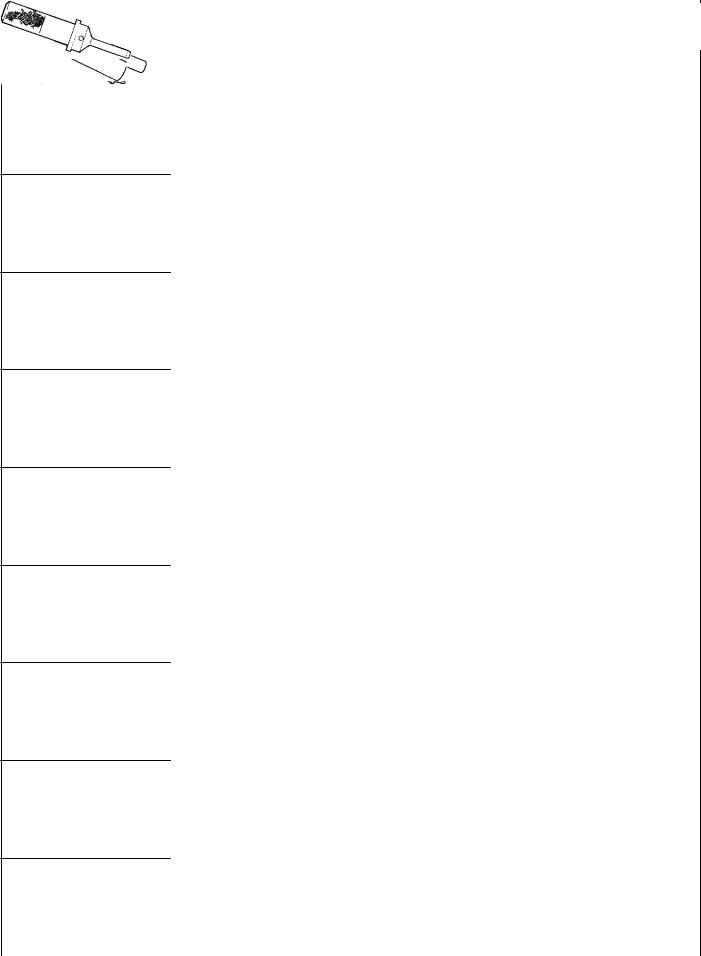
2. SPECIAL TOOLS |
|
|
|
|
|
|
|
|
|
Tool |
Number |
Name |
Use |
|
|
|
|
|
|
|
MB990767 |
Camshaft sprocket |
Removal of camshaft sprocket |
|
|
|
holder |
|
|
|
|
|
|
|
MB991614 |
Angle gauge |
Tightening cylinder head bolts |
|
|
|
MB996014 |
Valve spring |
Removal of valve spring split cones |
|
compressor |
|
|
|
|
MB996015 |
Flywheel stopper |
Locking the flywheel |
|
|
|
MB996016 |
Reamer |
Reaming valve guides |
|
|
|
MB996018 |
Slip gauge |
Measuring the crankshaft end play |
|
|
|
MB996020 |
Valve guide |
Pressing in valve guides |
|
remover |
|
|
|
|
MB996021 |
Valve stem seal |
Removal of valve guide seal |
|
remover |
|
|
|
|
|
MB996022 |
Valve seat installer |
Pressing in intake valve seat |
|
|
|
|
E Mitsubishi Motors Corporation |
July 1996 |
PWEE9602 |

11A-2-2 |
F8QT ENGINE - Special Tools |
||
|
|
|
|
Tool |
Number |
Name |
Use |
|
|
|
|
|
MB996023 |
Valve seat installer |
Pressing in intake valve seat |
|
|
|
|
|
MB996024 |
Reamer |
Reaming valve guides |
|
|
|
|
|
MB996025 |
Bearing puller |
Removal of intermediate shaft outer bearing |
|
|
|
|
|
MB996026 |
Bearing puller |
Removal of intermediate shaft inner bearing |
|
|
|
|
|
MB996027 |
Bearing installer |
Installation of intermediate shaft inner bearing |
|
|
|
|
|
MB996028 |
Bearing installer |
Installation of intermediate shaft outer bearing |
|
|
|
|
|
MB996029 |
Valve guide |
Pressing in valve guides |
|
|
installer |
|
|
|
|
|
|
MB996030 |
Measuring device |
Adjustment of fuel injection pump |
|
|
adapter |
|
|
|
|
|
|
MB996031 |
Valve stem seal |
Installation of valve guide seal |
|
|
installer |
|
|
|
|
|
E Mitsubishi Motors Corporation |
July 1996 |
PWEE9602 |

|
F8QT ENGINE - Special Tools |
11A-2-3 |
||
|
|
|
|
|
Tool |
Number |
Name |
Use |
|
|
|
|
|
|
|
MB996032 |
Tension gauge |
Measuring timing belt deflection |
|
|
|
|
|
|
|
MB996033 |
Tension gauge |
Measuring timing belt deflection |
|
|
|
|
|
|
|
MB996034 |
Sprocket stopper |
Removal of intermediate shaft sprocket |
|
|
|
|
|
|
|
MB996036 |
Hexagon socket |
Removal of injection pump sprocket screwed |
|
|
|
|
sleeve/nut assembly |
|
|
|
|
|
|
|
MB996037 |
Sprocket adapter |
Adjustment of fuel injection pump |
|
|
|
|
|
|
|
MB996038 |
Oil seal installer |
Installation of crankshaft oil seal (flywheel end) |
|
|
|
|
|
|
|
MB996039 |
Oil seal installer |
Installation of intermediate shaft oil seal |
|
|
|
|
|
|
|
MB996040 |
Oil seal installer |
Installation of crankshaft oil seal (timing gear |
|
|
|
|
end) |
|
|
|
|
|
|
|
MB996041 |
Special socket |
Removal of fuel injectors |
|
|
|
|
|
|
E Mitsubishi Motors Corporation |
July 1996 |
PWEE9602 |

11A-2-4 |
F8QT ENGINE - Special Tools |
||
|
|
|
|
Tool |
Number |
Name |
Use |
|
|
|
|
|
MB996042 |
Oil seal installer |
Installation of camshaft oil seal |
|
|
|
|
|
MB996043 |
Sprocket stopper |
Locking the injection pump sprocket |
|
|
|
|
|
MD998715 |
Pulley holder pin |
Retaining the camshaft sprocket (use together |
|
|
|
with MB990767) |
|
|
|
|
E Mitsubishi Motors Corporation |
July 1996 |
PWEE9602 |
F8QT ENGINE - Crankshaft Pulley |
11A-3-1 |
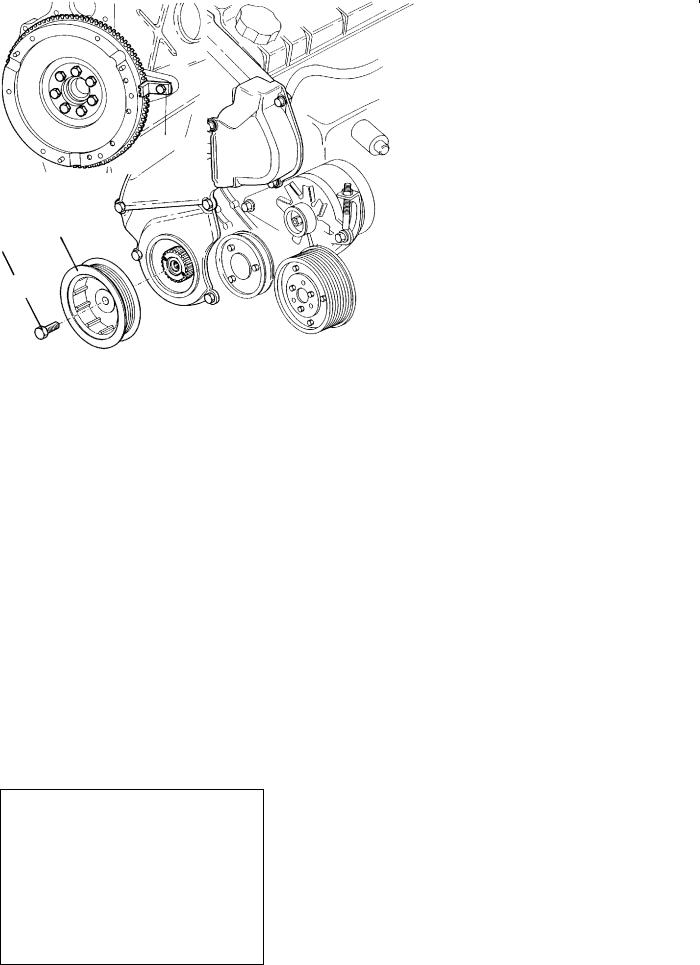
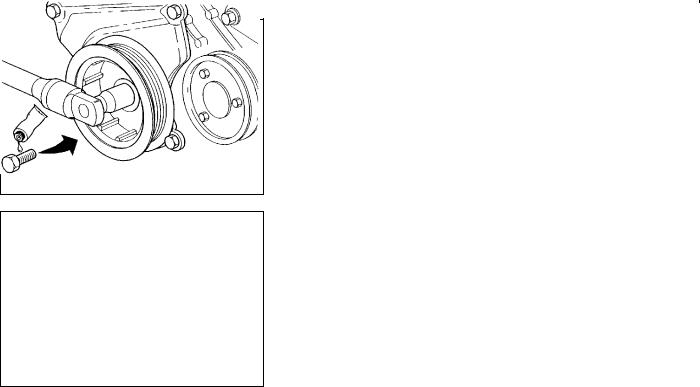
3. CRANKSHAFT PULLEY
2
120 Nm
1
REN0143
Removal steps
AA" "AA 1. Crankshaft pulley bolt 2. Crankshaft pulley
REMOVAL SERVICE POINT
AA"CRANKSHAFT PULLEY BOLT REMOVAL
Use special tool MB996015 to hold the flywheel during removal.
MB996015
REN0144
E Mitsubishi Motors Corporation |
July 1996 |
PWEE9602 |
11A-3-2 |
F8QT ENGINE - Crankshaft Pulley |
INSTALLATION SERVICE POINT
"AACRANKSHAFT PULLEY INSTALLATION
(1)Use special tool MB996015 to hold the flywheel during installation.
MB996015
REN0144
(2)Apply a locking agent to the screw thread of the bolt. Tighten the bolt to the specified torque.
REN0145
E Mitsubishi Motors Corporation |
July 1996 |
PWEE9602 |
F8QT ENGINE - Timing Belt |
11A-4-1 |
4. TIMING BELT
REMOVAL AND INSTALLATION
50 Nm 10 |
11 |
9
12
8
13
REN0001
Removal steps |
|
|
|
1. |
Bolt |
AA" "BA 8. |
Timing belt |
2. |
Bolt |
AB" "AA 9. |
Camshaft sprocket bolt |
3. |
Nut |
10. |
Camshaft sprocket |
4. |
Engine support bracket |
11. |
Camshaft sprocket key |
5. |
Timing gear case cover |
12. |
Timing belt tensioner |
6. |
Timing gear case cover |
13. |
Timing belt idler |
7. |
Timing gear case cover |
|
|
E Mitsubishi Motors Corporation |
July 1996 |
PWEE9602 |

11A-4-2
REN0002
F8QT ENGINE - Timing Belt
REMOVAL SERVICE POINTS
AA" TIMING BELT REMOVAL
(1)Turn the crankshaft clockwise so that the piston of No. 1 cylinder (flywheel end) is at TDC, with the following marks in line with each other:
D flywheel/clutch housing;
D rear guard plate/camshaft sprocket.
Scribe a mark on the injection pump mounting bracket.
(2)Insert an 8 mm diameter locking pin in the threaded hole of torx bolt 2 so that it engages the recess in the crankshaft web.
(3)Slacken the lock nut of the timing belt tensioner. Remove the timing belt.
AB" CAMSHAFT SPROCKET BOLT REMOVAL
(1)Use special tool MB990767, camshaft sprocket holder with pin MD998715 and remove the retaining bolt.
MB990767 |
REN0003 |
MB990767
50 Nm
REN0004
REN0005
E Mitsubishi Motors Corporation |
July 1996 |
INSTALLATION SERVICE POINTS
"AA CAMSHAFT SPROCKET BOLT INSTALLATION
(1)Smear the retaining bolt with a locking agent.
Use special tool MB990767, camshaft sprocket holder with pin MD998715 to stop the sprocket turning and then tighten the camshaft sprocket retaining bolt to 50 Nm.
"BA TIMING BELT INSTALLATION
(1)Turn the camshaft clockwise with special tool MB990767 until the mark on the camshaft sprocket is opposite the mark on the guard plate.
(2)Turn the crankshaft 1/4 revolution counter-clockwise from the TDC position of No. 1 cylinder and insert the 8 mm diameter locking pin in the recess in the crankshaft web.
(3)Align the mark on the injection pump sprocket with the mark on the mounting bracket (turn clockwise).
PWEE9602

F8QT ENGINE - Timing Belt |
11A-4-3 |
REN0006
MB996032
MB996033
REN0007
8EN0066
3 |
2 |
4 |
5 |
8EN0044
8EN0067
E Mitsubishi Motors Corporation |
July 1996 |
(4)Fit the timing belt so that the lines on the belt are aligned with the marks on the crankshaft and camshaft sprockets and the injection pump sprocket.
NOTE
D the direction of rotation of the belt (see the arrows
on the belt);
Dthe sequence in which the belt is fitted around the sprockets.
(5)Fit the special tool on the timing belt and the timing belt tensioner.
(6)Tension the timing belt with the aid of an M6 bolt.
Standard value: 7.5 mm
(7)Tighten the lock nut to the specified torque.
INSPECTION
TIMING BELT
Should either of the following defects be evident, replace the belt with a new one:
(1)Hardened back surface rubber.
Glossy, non-elastic and so hard that no mark is produced when scratched with a fingernail.
(2)Cracked back surface rubber.
(3)Cracked or separated canvas.
(4)Cracked tooth bottom.
(5)Cracks in back surface of belt.
(6)Abnormal wear on the sides of the belt. A normal belt should have clear-cut sides as if cut by a sharp knife.
PWEE9602
Loading...