


 Loading...
11A-0-1
ENGINE
6A1 SERIES
CONTENTS
GENERAL INFORMATION . . . . . . . . . . . . . . . . . . . . . . . . . . . . . . . . . . . . . . . . . . . |
11A-0-3 |
1. SPECIFICATIONS . . . . . . . . . . . . . . . . . . . . . . . . . . . . . . . . . . . . . . . . . . . . . . . |
11A-1-1 |
SERVICE SPECIFICATIONS . . . . . . . . . . . . . . . . . . . . . . . . . . . . . . . . . . |
11A-1-1 |
REWORK DIMENSIONS . . . . . . . . . . . . . . . . . . . . . . . . . . . . . . . . . . . . . . . |
11A-1-3 |
TORQUE SPECIFICATION . . . . . . . . . . . . . . . . . . . . . . . . . . . . . . . . . . . . |
11A-1-4 |
NEW TIGHTENING METHOD - BY USE OF BOLTS TO BE |
|
TIGHTENED IN PLASTIC AREA . . . . . . . . . . . . . . . . . . . . . . . . . . . . . . |
11A-1-7 |
SEALANTS . . . . . . . . . . . . . . . . . . . . . . . . . . . . . . . . . . . . . . . . . . . . . . . . . . . . . |
11A-1-7 |
FORM-IN-PLACE GASKET (FIPG) . . . . . . . . . . . . . . . . . . . . . . . . . . . . |
11A-1-8 |
2. SPECIAL TOOLS . . . . . . . . . . . . . . . . . . . . . . . . . . . . . . . . . . . . . . . . . . . . . . . . |
11A-2-1 |
3. DRIVE BELT . . . . . . . . . . . . . . . . . . . . . . . . . . . . . . . . . . . . . . . . . . . . . . . . . . . . . |
11A-3-1 |
4. TIMING BELT . . . . . . . . . . . . . . . . . . . . . . . . . . . . . . . . . . . . . . . . . . . . . . . . . . . . |
11A-4-1 |
5. FUEL AND EMISSION CONTROL PARTS . . . . . . . . . . . . . . . . . . . . . . |
11A-5-1 |
6. IGNITION SYSTEM . . . . . . . . . . . . . . . . . . . . . . . . . . . . . . . . . . . . . . . . . . . . . . |
11A-6-1 |
7. WATER PUMP AND WATER PIPE . . . . . . . . . . . . . . . . . . . . . . . . . . . . . . |
11A-7-1 |
8. INTAKE MANIFOLD AND EXHAUST MANIFOLD . . . . . . . . . . . . . . |
11A-8-1 |
9. ROCKER ARM AND CAMSHAFT <SOHC> . . . . . . . . . . . . . . . . . . . . |
11A-9-1 |
10. ROCKER COVER AND CAMSHAFT <MIVEC> . . . . . . . . . . . . . . . . . |
11A-10-1 |
11. ROCKER ARM AND ROCKER SHAFT CAP <MIVEC> . . . . . . . . |
11A-11-1 |
12. CYLINDER HEAD AND VALVES . . . . . . . . . . . . . . . . . . . . . . . . . . . . . . . . |
11A-12-1 |
13. OIL PUMP CASE AND OIL PAN . . . . . . . . . . . . . . . . . . . . . . . . . . . . . . . . |
11A-13-1 |
14. PISTON AND CONNECTING ROD . . . . . . . . . . . . . . . . . . . . . . . . . . . . . . |
11A-14-1 |
15. CRANKSHAFT, CYLINDER BLOCK, FLYWHEEL |
|
AND DRIVE PLATE . . . . . . . . . . . . . . . . . . . . . . . . . . . . . . . . . . . . . . . . . . . . . . |
11A-15-1 |
|
|
|
|
K Mitsubishi Motors Corporation |
Feb. 1997 |
PWEE9622 |

11A-0-2
NOTES
K Mitsubishi Motors Corporation |
Feb. 1997 |
PWEE9622 |

6A1 ENGINE (E-W) - General Information |
11A-0-3 |
GENERAL INFORMATION
GENERAL SPECIFICATIONS
Descriptions |
|
6A12 |
6A13 |
|
|
|
|
|
|
Type |
|
60è V, OHV, DOHC (for each bank) |
60è V, OHV, SOHC (for each bank) |
|
|
|
|
|
|
Number of cylinders |
|
6 |
6 |
|
|
|
|
|
|
Combustion chamber |
|
Pentroof type |
Pentroof type |
|
|
|
|
|
|
Total displacement dm3 |
|
1,998 |
2,498 |
|
Cylinder bore mm |
|
78.4 |
81.0 |
|
|
|
|
|
|
Piston stroke mm |
|
69.0 |
80.8 |
|
|
|
|
|
|
Compression ratio |
|
10.0 |
9.5*1 or 9.0*2 |
|
Valve timing |
Intake |
Opens |
15è (Low-speed cam) |
15è |
|
valve |
(BTDC) |
37.5è (High-speed cam) |
|
|
|
|
|
|
|
|
Closes |
41è (Low-speed cam) |
53è |
|
|
(ABDC) |
82.5è (High-speed cam) |
|
|
|
|
|
|
|
Exhaust |
Opens |
41è (Low-speed cam) |
53è |
|
valve |
(BBDC) |
75è (High-speed cam) |
|
|
|
|
|
|
|
|
Closes |
15è (Low-speed cam) |
15è |
|
|
(ATDC) |
30è (High-speed cam) |
|
|
|
|
|
|
Lubrication system |
|
Pressure feed, full-flow filtration |
Pressure feed, full-flow filtration |
|
|
|
|
|
|
Oil pump type |
|
Trochoid type |
Trochoid type |
|
|
|
|
|
|
Cooling system |
|
Water-cooled forced circulation |
Water-cooled forced circulation |
|
|
|
|
|
|
Water pump type |
|
Centrifugal impeller type |
Centrifugal impeller type |
|
|
|
|
|
|
NOTE
*1: Europe and Hong Kong
*2: GCC and Export
K Mitsubishi Motors Corporation |
Feb. 1997 |
PWEE9622 |
|
6A1 ENGINE (E-W) - Specifications |
11A-1-1 |
|
1. SPECIFICATIONS |
|
|
|
SERVICE SPECIFICATIONS |
|
|
|
|
|
|
|
Items |
|
Standard value |
Limit |
|
|
|
|
Timing belt |
|
|
|
|
|
|
|
Auto tensioner rod projection mm |
12.0 |
- |
|
|
|
|
|
Auto tensioner rod pushed-in amount (when pushed with a force |
1.0 or less |
- |
|
of 98 - 196 N) mm |
|
|
|
|
|
|
|
Rocker arm and camshaft <SOHC> |
|
|
|
|
|
|
|
Camshaft cam height mm |
Intake |
35.20 |
34.70 |
|
|
|
|
|
Exhaust |
34.70 |
34.20 |
|
|
|
|
Camshaft journal diameter mm |
|
45 |
- |
|
|
|
|
Rocker cover and camshaft <MIVEC>
Camshaft cam height mm |
Intake |
(Low-speed cam) |
|
|
|
|
|
(High-speed cam) |
|
|
|
|
Exhaust |
(Low-speed cam) |
|
|
|
|
|
(High-speed cam) |
|
|
|
Camshaft journal diameter mm |
|
|
|
|
|
Valve clearance mm |
Intake |
|
|
|
|
|
Exhaust |
|
|
|
|
34.34
36.46
34.40
35.86
26
0.10
0.13
33.84
35.96
33.90
35.36
-
-
-
Cylinder head and valve |
|
|
|
|
|
|
|
|
|
Flatness of cylinder head gasket surface mm |
- |
- |
||
|
|
|
|
|
Cylinder head gasket surface grinding limit (including grinding of |
Less than 0.03 |
- |
||
cylinder block gasket surface) mm |
|
|
||
|
|
|
|
|
Cylinder head overall height |
SOHC |
119.9 - 120.1 |
- |
|
mm |
|
|
|
|
MIVEC |
119.6 - 119.8 |
- |
||
|
||||
|
|
|
|
|
Cylinder head bolt nominal length mm |
- |
96.4 |
||
|
|
|
|
|
Valve margin mm |
Intake |
1.0 |
0.5 |
|
|
|
|
|
|
|
Exhaust |
1.3 |
0.8 |
|
|
|
|
|
|
Valve stem diameter mm |
|
6.0 |
- |
|
|
|
|
|
|
Valve stem-to-guide clearance |
Intake |
0.02 - 0.05 |
0.10 |
|
mm |
|
|
|
|
Exhaust |
0.04 - 0.07 |
0.15 |
||
|
||||
|
|
|
|
|
Valve face angle |
|
45è - 45.5è |
- |
|
|
|
|
|
|
Valve stem projection mm |
SOHC |
48.45 |
48.95 |
|
|
|
|
|
|
|
MIVEC |
48.40 |
48.90 |
|
|
|
|
|
|
K Mitsubishi Motors Corporation |
Feb. 1997 |
PWEE9622 |

11A-1-2 |
6A1 ENGINE (E-W) - Specifications |
|
|
|||
Items |
|
|
Standard value |
|
Limit |
|
|
|
|
||||
|
|
|
|
|
|
|
Overall valve length mm |
Intake |
SOHC |
113.02 |
|
112.52 |
|
|
|
|
|
|
|
|
|
|
MIVEC |
112.37 |
|
111.87 |
|
|
|
|
|
|
|
|
|
Exhaust |
SOHC |
115.32 |
|
114.82 |
|
|
|
|
|
|
|
|
|
|
MIVEC |
110.74 |
|
110.74 |
|
|
|
|
|
|
|
|
Valve spring free height mm |
SOHC |
|
49.9 |
|
|
48.9 |
|
|
|
|
|
|
|
|
MIVEC |
|
51.5 |
|
|
50.5 |
|
|
|
|
|
|
|
Valve spring load/installed |
SOHC |
|
265/43.4 |
|
- |
|
height N/mm |
|
|
|
|
|
|
MIVEC |
|
255/44.5 |
|
- |
||
|
|
|
||||
|
|
|
|
|
|
|
Valve spring squareness |
|
|
2è |
|
|
4è |
|
|
|
|
|
|
|
Valve seat contact width mm |
|
|
0.9 - 1.3 |
|
- |
|
|
|
|
|
|
|
|
Valve guide internal diameter mm |
|
6.6 |
|
|
- |
|
|
|
|
|
|
|
|
Valve guide projection mm |
SOHC |
|
14.0 |
|
|
- |
|
|
|
|
|
|
|
|
MIVEC |
|
19.0 |
|
|
- |
|
|
|
|
|
|
|
Oil pump case and oil pan |
|
|
|
|
|
|
|
|
|
|
|
||
Oil pump tip clearance mm |
|
|
0.06 - 0.18 |
|
- |
|
|
|
|
|
|
|
|
Oil pump side clearance mm |
|
|
0.04 - 0.10 |
|
- |
|
|
|
|
|
|
|
|
Oil pump body clearance mm |
|
|
0.10 - 0.18 |
|
0.35 |
|
|
|
|
|
|
|
|
Piston and connecting rod |
|
|
|
|
|
|
|
|
|
|
|
|
|
Piston outside diameter mm |
6A12 |
|
78.4 |
|
|
- |
|
|
|
|
|
|
|
|
6A13 |
|
81.0 |
|
|
- |
|
|
|
|
|
|
|
Piston ring side clearance mm |
No.1 ring |
|
0.02 |
- 0.06 |
|
- |
|
|
|
|
|
|
|
|
No.2 ring |
|
0.02 |
- 0.06 |
|
- |
|
|
|
|
|
|
|
Piston ring end gap mm |
No.1 ring |
|
0.20 - 0.35 |
|
0.8 |
|
|
|
|
|
|
|
|
|
No.2 ring |
|
0.35 |
- 0.50 |
|
0.8 |
|
|
|
|
|
|
|
|
Oil ring |
|
0.20 |
- 0.50 |
|
1.0 |
|
|
|
|
|
|
|
Piston pin outside diameter mm |
|
|
19.0 |
|
|
- |
|
|
|
|
|||
Piston pin press-in load (at room temperature) N |
4,900 - 14,700 |
|
- |
|||
|
|
|
|
|
|
|
Crankshaft pin oil clearance mm |
|
0.02 |
- 0.05 |
|
0.1 |
|
|
|
|
|
|
||
Connecting rod big end side clearance mm |
|
0.10 - 0.25 |
|
0.4 |
||
|
|
|
|
|
||
Crankshaft, cylinder block, flywheel and drive plate |
|
|
|
|
||
|
|
|
|
|
||
Crankshaft end play mm |
|
|
0.05 - 0.25 |
|
0.4 |
|
|
|
|
|
|
|
|
K Mitsubishi Motors Corporation |
Feb. 1997 |
PWEE9622 |

|
|
|
|
|
6A1 ENGINE (E-W) - Specifications |
|
11A-1-3 |
||
Items |
|
|
|
|
|
|
Standard value |
|
Limit |
|
|
|
|
|
|
|
|||
|
|
|
|
|
|
|
|
||
Crankshaft journal |
diameter |
6A12 |
|
53.0 |
|
- |
|||
mm |
|
|
|
|
|
|
|
|
|
|
|
|
|
6A13 |
|
56.0 |
|
- |
|
|
|
|
|
|
|
|
|||
|
|
|
|
|
|
|
|
||
Crankshaft pin diameter mm |
|
6A12 |
|
43.0 |
|
- |
|||
|
|
|
|
|
|
|
|
|
|
|
|
|
|
|
6A13 |
|
51.0 |
|
- |
|
|
|
|
|
|
|
|||
Crankshaft journal oil clearance mm |
|
0.02 - 0.04 |
|
0.1 |
|||||
|
|
|
|
|
|
||||
Cylinder block gasket surface flatness mm |
|
0.05 |
|
- |
|||||
|
|
|
|
|
|
||||
Cylinder block gasket surface grinding limit (including grinding of |
- |
|
0.2 |
||||||
cylinder head gasket surface) mm |
|
|
|
|
|||||
|
|
|
|
|
|
|
|
||
Cylinder |
block overall height |
6A12 |
|
190.0 |
|
- |
|||
mm |
|
|
|
|
|
|
|
|
|
|
|
|
|
6A13 |
|
209.0 |
|
- |
|
|
|
|
|
|
|
|
|||
|
|
|
|
|
|
|
|||
Cylinder block cylindricity mm |
|
|
0.01 or less |
|
- |
||||
|
|
|
|
|
|
|
|||
Cylinder block internal diame- |
6A12 |
|
78.4 |
|
- |
||||
ter mm |
|
|
|
|
|
|
|
|
|
|
|
|
|
6A13 |
|
81.0 |
|
- |
|
|
|
|
|
|
|
|
|||
|
|
|
|
|
|
|
|||
Bearing cap bolt nominal length mm |
|
- |
|
71.1 |
|||||
|
|
|
|
|
|
||||
Piston-to-cylinder clearance mm |
|
0.02 - 0.04 |
|
- |
|||||
REWORK DIMENSIONS |
|
|
|
|
|
||||
|
|
|
|
|
|||||
Item |
|
|
|
|
|
|
|
Standard |
|
|
|
|
|
|
|
|
|||
|
|
|
|
|
|
|
|
||
Cylinder head and valves |
|
|
|
|
|
|
|||
|
|
|
|
||||||
Cylinder head oversize valve guide hole diameter mm |
0.05 O.S. |
11.05 - 11.07 |
|||||||
|
|
|
|
|
|
|
|
||
|
|
|
|
|
|
0.25 O.S. |
11.25 - 11.27 |
||
|
|
|
|
|
|
|
|
||
|
|
|
|
|
|
0.50 O.S. |
11.50 - 11.52 |
||
|
|
|
|
|
|||||
Oversize intake valve seat |
|
SOHC |
0.3 O.S. |
29.80 - 29.82 |
|||||
ring hole diameter mm |
|
|
|
|
|
|
|
||
|
|
|
0.6 O.S. |
30.10 - 30.12 |
|||||
|
|
|
|
|
|
||||
|
|
|
|
|
|
|
|||
|
|
|
|
MIVEC |
0.3 O.S. |
32.30 - 32.32 |
|||
|
|
|
|
|
|
|
|
||
|
|
|
|
|
|
0.6 O.S. |
32.60 - 32.62 |
||
|
|
|
|
|
|
|
|||
Oversize |
exhaust |
valve |
|
SOHC |
0.3 O.S. |
27.80 - 27.82 |
|||
seat ring diameter mm |
|
|
|
|
|
|
|
||
|
|
|
0.6 O.S. |
28.10 - 28.12 |
|||||
|
|
|
|
|
|
||||
|
|
|
|
|
|
|
|||
|
|
|
|
MIVEC |
0.3 O.S. |
29.80 - 29.82 |
|||
|
|
|
|
|
|
|
|
||
|
|
|
|
|
|
0.6 O.S. |
30.10 - 30.12 |
||
|
|
|
|
|
|
|
|
|
|
K Mitsubishi Motors Corporation |
Feb. 1997 |
PWEE9622 |

11A-1-4 |
6A1 ENGINE (E-W) - Specifications |
|
TORQUE SPECIFICATION |
||
Items |
|
Nm |
|
||
|
|
|
Alternator and drive belt |
|
|
|
|
|
Alternator pivot nut |
|
44 |
|
|
|
Alternator bolt |
|
21 |
|
|
|
Oil level gauge guide |
|
23 |
|
|
|
Tensioner pulley |
|
15 |
|
|
|
Engine hanger |
|
23 |
|
|
|
Tensioner pulley bracket A |
|
45 |
|
|
|
Crankshaft bolt |
|
182 |
|
|
|
Engine cover |
|
3 |
|
|
|
Timing belt |
|
|
|
|
|
Timing belt front cover |
|
11 |
|
|
|
Engine support bracket |
|
49 |
|
|
|
Angle sensor |
|
9 |
|
|
|
Angle sensor connector bracket |
|
11 |
|
|
|
Tensioner pulley |
|
48 |
|
|
|
Tensioner arm |
|
24 |
|
|
|
Auto tensioner |
|
21 |
|
|
|
Camshaft sprocket bolt |
|
88 |
|
|
|
Idler pulley |
|
35 |
|
|
|
Timing belt rear cover |
|
11 |
|
|
|
Angle sensor connector bracket |
|
11 |
|
|
|
Fuel and emission control parts |
||
|
|
|
Air intake plenum stay |
|
18 |
|
|
|
Connector bracket |
|
11 |
|
|
|
EGR valve |
|
22 |
|
|
|
Throttle body |
|
12 |
|
|
|
Air intake plenum |
|
18 |
|
|
|
Delivery pipe |
|
12 |
|
|
|
Fuel pipe |
|
9 |
|
|
|
Fuel pressure regulator |
|
9 |
|
|
|
Alternator bracket |
|
23 |
|
|
|
K Mitsubishi Motors Corporation |
Feb. 1997 |
PWEE9622 |

6A1 ENGINE (E-W) - Specifications |
11A-1-5 |
||
Items |
|
Nm |
|
|
|
||
|
|
|
|
Ignition system |
|
|
|
|
|
|
|
Spark plug |
|
25 |
|
|
|
|
|
Water cover (SOHC) |
|
11 |
|
|
|
|
|
Distributor (SOHC) |
|
13 |
|
|
|
|
|
Ignition failure sensor (MIVEC) |
|
10 |
|
|
|
|
|
Condenser bracket assembly (MIVEC) |
|
5 |
|
|
|
|
|
Ignition coil (MIVEC) |
|
10 |
|
|
|
|
|
Water pump and water pipe |
|
|
|
|
|
|
|
Engine hanger (MIVEC) |
|
11 |
|
|
|
|
|
Engine coolant temperature gauge unit |
|
11 |
|
|
|
|
|
Engine coolant temperature sensor |
|
29 |
|
|
|
|
|
Heater pipe (SOHC) |
|
23 |
|
|
|
|
|
Water inlet fitting |
|
18 |
|
|
|
|
|
Water outlet fitting |
|
18 |
|
|
|
|
|
Thermostat housing |
|
23 |
|
|
|
|
|
Water pipe |
|
13 |
|
|
|
|
|
Water pump |
|
23 |
|
|
|
|
|
Intake manifold and exhaust manifold |
|
|
|
|
|
|
|
Intake manifold |
|
17 |
|
|
|
|
|
Heat protector |
|
13 |
|
|
|
|
|
Exhaust manifold stay |
|
44 |
|
|
|
|
|
Exhaust manifold |
|
49 |
|
|
|
|
|
Rocker arm and camshaft <SOHC> |
|
|
|
|
|
|
|
Rocker cover |
|
4 |
|
|
|
|
|
Rocker arm and rocker shaft |
|
31 |
|
|
|
|
|
Thrust case |
|
24 |
|
|
|
|
|
Rocker arm and camshaft <MIVEC> |
|
|
|
|
|
|
|
Rocker cover |
|
4 |
|
|
|
|
|
Oil control valve holder |
|
9 |
|
|
|
|
|
Cam cap |
|
24 |
|
|
|
|
|
Bearing cap M6 |
|
11 |
|
|
|
|
|
Bearing cap M8 |
|
24 |
|
|
|
|
|
K Mitsubishi Motors Corporation |
Feb. 1997 |
PWEE9622 |

11A-1-6 |
6A1 ENGINE (E-W) - Specifications |
||
Items |
|
Nm |
|
|
|||
|
|
|
|
Arm spring holder |
|
11 |
|
|
|
|
|
Rocker arm and rocker shaft cap <MIVEC> |
|
||
|
|
|
|
Rocker shaft cap |
|
11 |
|
|
|
|
|
Cylinder head and valves |
|
|
|
|
|
|
|
Cylinder head bolt |
|
20 |
+ 120è + 120è |
|
|
|
|
Oil pan and oil pump |
|
|
|
|
|
|
|
Oil pressure switch |
|
10 |
|
|
|
|
|
Oil filter cover |
|
21 |
|
|
|
|
|
Water hose |
|
30 |
|
|
|
|
|
Bolt |
|
68 |
|
|
|
|
|
Drain plug |
|
39 |
|
|
|
|
|
Oil level sensor |
|
9 |
|
|
|
|
|
Oil pan |
|
7 |
|
|
|
|
|
Oil screen |
|
19 |
|
|
|
|
|
Baffle plate |
|
9 |
|
|
|
|
|
Relief plug |
|
44 |
|
|
|
|
|
Oil pump case |
|
14 |
|
|
|
|
|
Oil pump case cover |
|
12 |
|
|
|
|
|
Piston and connecting rod |
|
|
|
|
|
|
|
Connecting rod |
|
18 |
+ 90è - 100è |
|
|
|
|
Crankshaft, cylinder block, flywheel and drive plate |
|
||
|
|
|
|
Detonation sensor |
|
23 |
|
|
|
|
|
Idler pulley bracket |
|
35 |
|
|
|
|
|
Flywheel bolt |
|
98 |
|
|
|
|
|
Drive plate bolt |
|
98 |
|
|
|
|
|
Rear plate |
|
11 |
|
|
|
|
|
Bell housing cover |
|
9 |
|
|
|
|
|
Oil seal case |
|
11 |
|
|
|
|
|
Bearing cap bolt |
|
25 |
+ 90è - 100è |
|
|
|
|
K Mitsubishi Motors Corporation |
Feb. 1997 |
PWEE9622 |

6A1 ENGINE (E-W) - Specifications |
11A-1-7 |
NEW TIGHTENING METHOD - BY USE OF BOLTS TO BE TIGHTENED IN PLASTIC AREA
A new type of bolts, to be tightened in plastic area, is currently used in some parts of the engine. The tightening method for the bolts is different from the conventional one. Be sure to observe the method described in the text when tightening the bolts.
Service limits are provided for the bolts. Make sure that the service limits described in the text are strictly observed.
JAreas where the bolts are in use:
(1)Cylinder head bolts
(2)Main bearing cap bolts
(3)Connecting rod cap bolts
JTightening Method
After tightening the bolts to the specified torque, tighten them another 90è to 100è, or 240è (twice 120è). The tightening method varies on different areas. Observe the tightening method described in the text.
SEALANTS
Item |
Specified sealant |
Quantity |
|
|
|
|
|
Water pump* |
Mitsubishi Genuine Part No. MD970389 or equivalent |
As required |
|
|
|
|
|
Water outlet fitting* |
Mitsubishi Genuine Part No. MD970389 or equivalent |
As required |
|
|
|
|
|
Engine coolant temperature sensor |
3M |
Nut Locking Part No. 4171 or equivalent |
As required |
|
|
|
|
Engine coolant temperature gauge unit |
3M |
ATD Part No. 8660 or equivalent |
As required |
|
|
|
|
Camshaft bearing |
3M |
ATD Part No. 8660 or equivalent |
As required |
|
|
|
|
Cam cap |
3M |
ATD Part No. 8660 or equivalent |
As required |
|
|
|
|
Oil control valve |
3M |
ATD Part No. 8660 or equivalent |
As required |
|
|
|
|
Camshaft holder* |
Mitsubishi Genuine Part No. MD970389 or equivalent |
As required |
|
|
|
|
|
Rocker cover |
3M |
ATD Part No. 8660 or equivalent |
As required |
|
|
|
|
Oil pump case* |
Mitsubishi Genuine Part No. MD970389 or equivalent |
As required |
|
|
|
|
|
Oil pan* |
Mitsubishi Genuine Part No. MD970389 or equivalent |
As required |
|
|
|
|
|
Oil pressure switch |
3M |
ATD Part No. 8660 or equivalent |
As required |
|
|
|
|
Oil seal case* |
Mitsubishi Genuine Part No. MD970389 or equivalent |
As required |
|
|
|
|
|
Drive plate bolt |
3M |
Nut Locking Part No. 4171 or equivalent |
As required |
|
|
|
|
Flywheel bolt |
3M |
Nut Locking Part No. 4171 or equivalent |
As required |
|
|
|
|
*: parts sealed by foam-in-place gasket (FIPG)
K Mitsubishi Motors Corporation |
Feb. 1997 |
PWEE9622 |
11A-1-8 |
6A1 ENGINE (E-W) - Specifications |
FORM-IN-PLACE GASKET (FIPG)
The engine has several areas where the form-in-place gasket (FIPG) is in use. To ensure that the gasket fully serves its purpose, it is necessary to observe some precautions when applying the gasket. Bead size, continuity and location are of paramount importance. Too thin a bead could cause leaks. Too thick a bead, on the other hand, could be squeezed out of location, causing blocking or narrowing of the fluid feed line. To eliminate the possibility of leaks from a joint, therefore, it is absolutely necessary to apply the gasket evenly without a break, while observing the correct bead size.
The FIPG used in the engine is a room temperature vulcanisation (RTV) type and is supplied in a 100-gram tube (Part No. MD970389 or MD997110). Since the RTV hardens as it reacts with the moisture in the atmospheric air, it is normally used in the metallic flange areas. The FIPG, Part No. MD970389, can be used for sealing both engine oil and coolant, while Part No. MD997110 can only be used for engine oil sealing.
Disassembly
The parts assembled with the FIPG can be easily disassembled without use of a special method. In some cases, however, the sealant between the joined surfaces may have to be broken by lightly striking with a mallet or similar tool. A flat and thin gasket scraper may be lightly hammered in between the joined surfaces. In this case, however, care must be taken to prevent damage to the joined surfaces. For removal of the oil pan, the special tool “Oil Pan Remover” (MD998727) is available. Be sure to use the special tool to remove the oil pan.
Surface Preparation
Thoroughly remove all substances deposited on the gasket application surfaces, using a gasket scraper or wire brush. Check to ensure that the surfaces to which the FIPG is to be applied is flat. Make sure that there are no oils, greases and foreign substances deposited on the application surfaces. Do not forget to remove the old sealant remained in the bolt holes.
Form-in-Place Gasket Application
When assembling parts with the FIPG, you must observe some precautions, but the procedures is very simple as in the case of a conventional precut gasket.
Applied FIPG bead should be of the specified size and without breaks. Also be sure to encircle the bolt hole circumference with a completely continuous bead. The FIPG can be wiped away unless it is hardened. While the FIPG is still moist (in less than 15 minutes), mount the parts in position. When the parts are mounted, make sure that the gasket is applied to the required area only. In addition, do not apply any oil or water to the sealing locations or start the engine until a sufficient amount of time (about one hour) has passed after installation is completed.
The FIPG application procedure may vary on different areas. Observe the procedure described in the text when applying the FIPG.
K Mitsubishi Motors Corporation |
Feb. 1997 |
PWEE9622 |
|
|
6A1 ENGINE (E-W) - Special Tools |
11A-2-1 |
||||
2. SPECIAL TOOLS |
|
|
|
|
|
||
Tool |
|
Number |
|
Name |
|
Use |
|
|
|
|
|
||||
|
|
|
|
|
|
|
|
|
|
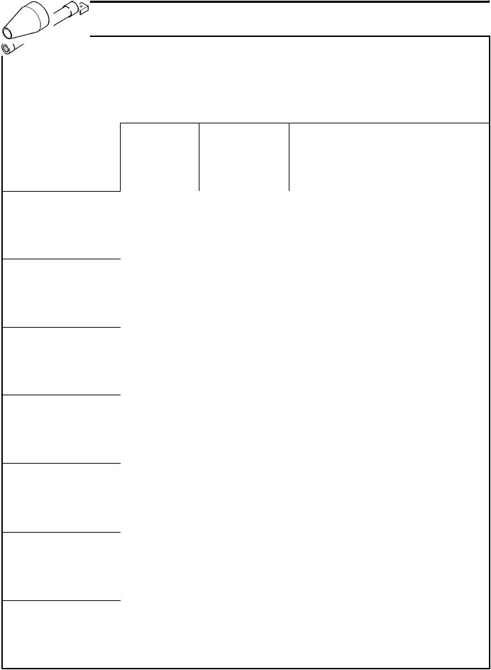
MB990685 |
|
Torque wrench |
|
Adjustment of timing belt tension |
|
|
|
|
|
|
|
|
|
MB990938 |
Handle |
Use with MD998776 |
MB990767 |
Crankshaft pulley |
Holding camshaft sprocket when loosening |
|
holder |
and tightening of bolt. |
|
|
Use with MD998719 |
|
|
|
MB991477 |
Valve adjusting |
Adjustment of valve clearance (MIVEC) |
|
wrench |
|
|
|
|
MB991478 |
Valve adjusting |
Adjustment of valve clearance (MIVEC) |
|
wrench feeler |
|
|
gauge set |
|
|
|
|
MB991479 |
Rocker arm |
Adjustment of valve clearance (MIVEC) |
|
piston checker |
|
|
|
|
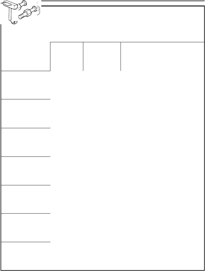
MB991614 |
Angle gauge |
Tightening cylinder head bolt |
|
|
|
MB991653 |
Cylinder head bolt |
Tightening and loosening of cylinder head bolt |
|
wrench |
|
|
|
|
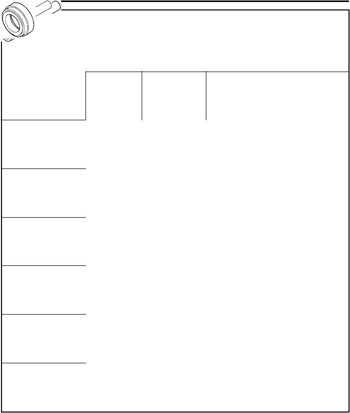
MB991659 |
Guide D |
Removal of piston pin (Use with MD998780) |
|
|
|
K Mitsubishi Motors Corporation |
Feb. 1997 |
PWEE9622 |
11A-2-2 |
|
6A1 ENGINE (E-W) - Special Tools |
||||
Tool |
|
Number |
|
Name |
|
Use |
|
|
|
||||
|
|
|
|
|
|
|
|
|
MD998440 |
|
Leak-down tester |
|
Leak-down test of lash adjuster |
|
|
|
|
|
|
|
MD998441 |
Lash adjuster |
Air bleeding of lash adjuster |
|
retainer |
|
MD998442 |
Air bleed wire |
Air bleeding of lash adjuster |
|
|
|
MD998443 |
Lash adjuster |
Retainer for holding lash adjuster in rocker arm |
|
holder |
at time of removal and installation of rocker arm |
|
|
and rocker shaft assembly |
|
|
|
MD998713 |
Camshaft oil seal |
Installation of camshaft oil seal |
|
installer |
|
|
|
|
MD998716 |
Crankshaft wrench |
Rotation of crankshaft when installing piston |
|
|
and timing belt. |
|
|
|
MD998717 |
Crankshaft front oil |
Installation of crankshaft front oil seal |
|
seal installer |
|
|
|
|
MD998719 |
Pulley holder pin |
Use with MB990767 |
|
(2) |
|
|
|
|
MD998727 |
Oil pan remover |
Removal of oil pan |
|
|
|
K Mitsubishi Motors Corporation |
Feb. 1997 |
PWEE9622 |
|
|
6A1 ENGINE (E-W) - Special Tools |
11A-2-3 |
||||
Tool |
|
Number |
|
Name |
|
Use |
|
|
|
|
|
||||
|
|
|
|
|
|
|
|
|
|
MD998735 |
|
Valve spring |
|
Compression of valve spring |
|
|
|
|
|
compressor |
|
|
|
|
|
|
|
|
|
|
|
MD998754 |
Pin |
Use with MB990767 |
MD998767 |
Tensioner pulley |
Adjustment of timing belt tension |
|
socket wrench |
|
|
|
|
MD998772 |
Valve spring |
Removal and installation of valve and related |
|
compressor |
parts |
|
|
|
MD998774 |
Valve stem seal |
Installation of valve stem seal |
|
installer |
|
|
|
|
MD998775 |
Valve stem seal |
Installation of valve stem seal |
|
installer |
|
|
|
|
MD998776 |
Crankshaft rear oil |
Installation of crankshaft rear oil seal |
|
seal installer |
Use with MB990938 |
|
|
|
MD998777 |
Camshaft oil seal |
Installation of camshaft oil seal |
|
installer adapter |
|
|
|
|
K Mitsubishi Motors Corporation |
Feb. 1997 |
PWEE9622 |
11A-2-4 |
|
6A1 ENGINE (E-W) - Special Tools |
||||
Tool |
|
Number |
|
Name |
|
Use |
|
|
|
||||
|
|
|
|
|
|
|
|
|
MD998780 |
|
SETTING TOOL |
|
Removal and installation of piston pin |
|
|
|
|
Piston pin |
|
|
|
|
|
|
|
|
|
MD998781 |
Flywheel stopper |
Holding flywheel and drive plate |
MD998784 |
Valve spring |
Compression of valve spring (MIVEC) |
|
compressor |
(Use with MD998772) |
|
adapter |
|
|
|
|
K Mitsubishi Motors Corporation |
Feb. 1997 |
PWEE9622 |
6A1 ENGINE (E-W) - Drive Belt |
11A-3-1 |
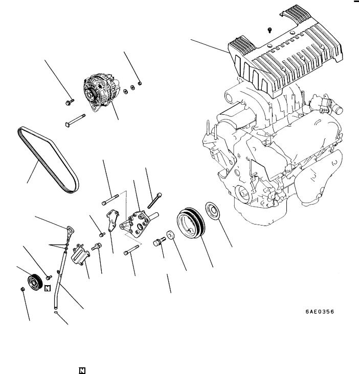
3. DRIVE BELT
REMOVAL AND INSTALLATION <SOHC>
3 Nm
16
44 Nm
21 Nm
2
|
44 Nm |
|
|
|
11 |
|
|
9 |
1 |
|
|
3 |
23 Nm |
|
|
|
|
23 Nm |
|
|
6 |
|
7 |
|
|
|
|
10 |
44 Nm |
|
8 |
|
4
15 Nm |
5 |
|
Removal steps
1.Drive belt
2.Alternator
3.Oil level gauge (dipstick)
4.Oil level gauge guide
5.O-ring
6.Tensioner pulley
7.Engine hanger
8.Tensioner pulley bracket A
15
12
13 14
182 Nm
9.Tensioner pulley bracket B
10.Adjusting stud
11.Adjusting bolt
GA+ +AG 12. Crankshaft bolt
13.Special washer
14.Crankshaft pulley
15.Flange
16.Engine cover
K Mitsubishi Motors Corporation |
Feb. 1997 |
PWEE9622 |
11A-3-2 |
6A1 ENGINE (E-W) - Drive Belt |
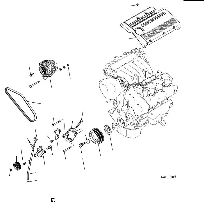
REMOVAL AND INSTALLATION <MIVEC>
3 Nm
16
21 Nm
44 Nm
2
1
44 Nm
9
3
23 Nm
23 Nm
7
6
10
44 Nm
8
4
15 Nm
5
Removal steps
1.Drive belt
2.Alternator
3.Oil level gauge (dipstick)
4.Oil level gauge guide
5.O-ring
6.Tensioner pulley
7.Engine hanger
8.Tensioner pulley bracket A
11
13
12 |
15 |
|
14 |
||
|
||
182 Nm |
|
9.Tensioner pulley bracket B
10.Adjusting stud
11.Adjusting bolt
GA+ +AG 12. Crankshaft bolt
13.Special washer
14.Crankshaft pulley
15.Flange
16.Engine cover
K Mitsubishi Motors Corporation |
Feb. 1997 |
PWEE9622 |
6A1 ENGINE (E-W) - Drive Belt |
11A-3-3 |
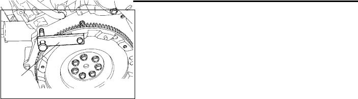
REMOVAL SERVICE POINTS
GA+CRANKSHAFT PULLEY BOLT REMOVAL
(1)Hold the flywheel or drive plate in position with the special tool before removing the crankshaft pulley bolts.
INSTALLATION SERVICE POINTS |
|
+AGCRANKSHAFT PULLEY BOLT INSTALLATION |
|
(1) |
Hold the flywheel or drive plate in position with the special |
MD998781 |
tool before installing the crankshaft pulley bolts. |
6AE0039 |
|
K Mitsubishi Motors Corporation |
Feb. 1997 |
PWEE9622 |

6A1 ENGINE (E-W) - Timing Belt |
11A-4-1 |
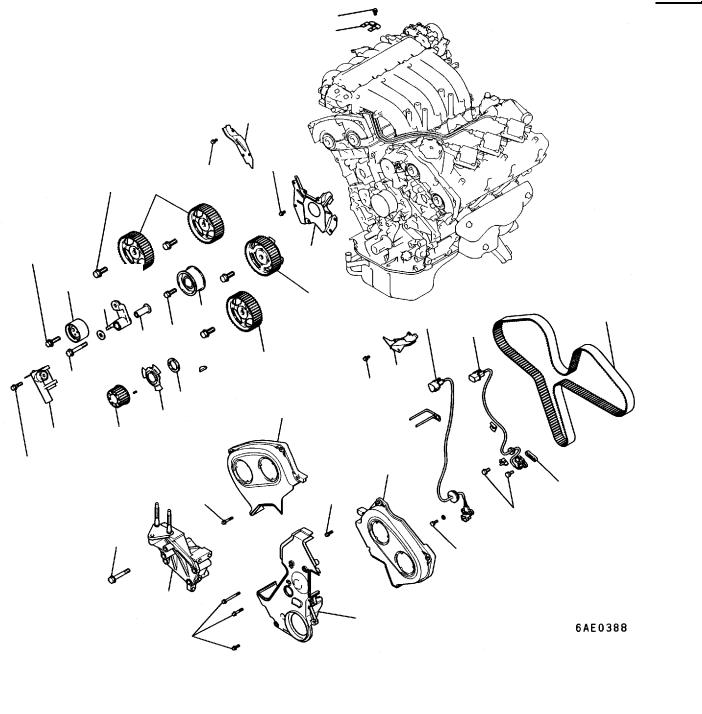
4. TIMING BELT
REMOVAL AND INSTALLATION <SOHC>
24
|
|
11 Nm |
|
|
Removal steps |
|
|
||
1. |
Timing belt |
front cover, upper right |
+BG 10. |
Auto tensioner |
2. |
Timing belt |
front cover, upper left |
11. |
Crankshaft sprocket |
3. |
Timing belt |
front cover, lower |
12. |
Sensing plate |
4. |
Engine support bracket |
13. |
Crankshaft spacer |
|
5. |
Angle sensor |
GB+ +AG 14. |
Camshaft sprocket bolt |
|
GA+ +CG 6. Timing belt |
|
15. |
Camshaft sprocket |
|
7. |
Tensioner pulley |
16. |
Idler pulley |
|
8. |
Tensioner arm |
17. |
Timing belt rear cover, center |
|
9. |
Tensioner spacer |
18. |
Connector bracket |
|
K Mitsubishi Motors Corporation |
Feb. 1997 |
PWEE9622 |
11A-4-2 |
6A1 ENGINE (E-W) - Timing Belt |
REMOVAL AND INSTALLATION <MIVEC>
11 Nm
88 Nm 17
16
48 Nm
9
10
19
11 35 Nm
44 Nm
15
14
12 13
22 Nm
11 Nm
49 Nm
12 Nm
23
21
11 Nm
22
18
5 |
8 |
|
6 |
||
|
17
20
11 Nm
1
2
9 Nm |
7 |
|
|
|
9 Nm |
|
9 Nm |
4
3
11 Nm
Removal steps |
|
|
|
1. |
Timing belt front cover, upper right |
13. |
Crankshaft sprocket |
2. |
Timing belt front cover, upper left |
14. |
Sensing plate |
3. |
Timing belt front cover, lower |
15. |
Washer |
4. |
Engine support bracket |
GB+ +AG 16. |
Camshaft sprocket bolt |
5. |
Angle sensor |
17. |
Camshaft sprocket |
6. |
Angle sensor |
18. |
Camshaft sprocket with sensing |
7. |
Spacer |
|
plate |
GA+ +DG 8. |
Timing belt |
19. |
Idler pulley |
9. |
Tensioner pulley |
20. |
Timing belt rear cover, left |
10. |
Tensioner arm |
21. |
Timing belt rear cover, right |
11. |
Tensioner spacer |
22. |
Timing belt rear cover, center |
+BG 12. |
Auto tensioner |
23. |
Connector bracket |
K Mitsubishi Motors Corporation |
Feb. 1997 |
PWEE9622 |
6A1 ENGINE (E-W) - Timing Belt |
11A-4-3 |
MB990767
MD998719
REMOVAL SERVICE POINTS
GA+ TIMING BELT REMOVAL
(1)Mark the belt running direction for reference in reinstallation.
(2)Loosen the bolt that secures the tensioner pulley to remove the timing belt.
6AE0135
6AE0044
GB+ CAMSHAFT SPROCKET BOLT REMOVAL
6AE0137
MB990767
MD998754 6AE0045
MD998719 |
INSTALLATION SERVICE POINTS |
|
+AG CAMSHAFT SPROCKET BOLT INSTALLATION |
MB990767
6AE0138
K Mitsubishi Motors Corporation |
Feb. 1997 |
PWEE9622 |

11A-4-4 |
6A1 ENGINE (E-W) - Timing Belt |
MD998754
MB990767
6AE0048
(B) (A)
6AE0049
6AE0050
6AE0329
Timing mark
6AE0358
K Mitsubishi Motors Corporation |
Feb. 1997 |
+BG AUTO TENSIONER SETTING
(1)Set the auto tensioner in a vice, while making sure it is not tilted.
(2)Slowly close the vice to force the rod in until the set hole (A) of the rod is lined up with the set hole (B) of the cylinder.
(3)Insert a 1.4 mm wire in the set hole.
(4)Remove the auto tensioner from the vice.
+CG TIMING BELT INSTALLATION
(1)Turn the crankshaft sprocket so that its timing mark will be away from the mating timing mark by approx. three teeth.
Caution
J If the timing marks are aligned, the piston is brought to the TDC. When the camshaft is turned under this condition, the valves may interfere with the piston.
(2)Bring the timing marks of the camshaft sprockets as shown in the illustration.
PWEE9622

6A1 ENGINE (E-W) - Timing Belt |
11A-4-5 |
6AE0331
6AE0143
6AE0057
MD998767
MB990685
6AE0058
K Mitsubishi Motors Corporation |
Feb. 1997 |
(3)Align the timing mark on the crankshaft sprocket with that on the cylinder block side.
(4)Fit the timing belt on the sprockets in the following order:
1)Fit the timing belt on the crankshaft sprocket and then, while giving tension to the belt, fit it on the water pump sprocket.
2)Fit the belt on the left bank camshaft sprocket.
3)Fit the belt on the idler pulley while keeping it tight.
4)Align the timing mark on the right bank camshaft sprocket with the mark on the cylinder block, and then fit the belt on the camshaft sprocket.
Caution
JThe camshaft sprockets are prone to rotate. Avoid giving excessive tension to the timing belt when it is fitted.
5)Make sure that the left bank portion of the belt is not slack when the belt is fitted on the tensioner pulley. If it is slack, remove the belt and fit it again beginning with the first step.
(5)Move the tensioner pulley in the direction of the arrow and hold it in raised position by tightening the tensioner pulley bolt.
(6)Check that all timing marks are aligned correctly.
(7)Turn the crankshaft counterclockwise a quarter turn.
(8)Turn back the crankshaft clockwise until the timing marks align again.
(9)Install the special tool and a torque wrench of 0 - 5 Nm to the tensioner pulley.
(10)Torque the tensioner pulley to 3 Nm with the torque wrench.
(11)While holding the tensioner pulley, tighten the center bolt to specification.
(12)Turn the crankshaft clockwise 2 turns and let it stand for about 5 minutes.
PWEE9622

11A-4-6 |
6A1 ENGINE (E-W) - Timing Belt |
MD998716
6AE0051
6AE0311
6AE0053
Paper clip
6AE0054
6AE0055
K Mitsubishi Motors Corporation |
Feb. 1997 |
+DG TIMING BELT INSTALLATION
(1)Turn the crankshaft sprocket so that its timing mark will be away from the mating timing mark by approx. three teeth.
Caution
J If the timing marks are aligned, the piston is brought to the TDC. When the camshaft is turned under this condition, the valves may interfere with the piston.
(2)Bring the timing marks of the camshaft sprockets as shown in the illustration.
Caution
J If one of the camshaft sprockets on the right bank is turned with the timing mark on the other sprocket aligned, there may be danger for the intake and exhaust valves to interfere with each other.
(3)Align the timing mark on the crankshaft sprocket with the mating timing mark, and then turn the crankshaft counterclockwise by one tooth.
(4)Place the timing belt over the sprockets in the following method.
Caution
J The camshaft sprockets on the right bank can turn very easily because of the valve spring tension. Use care not to allow your fingers to get caught between the sprockets.
1) Align the timing mark of the right bank exhaust camshaft sprocket with the mating timing mark and hold the timing belt on the sprocket with a paper
clip.
2) Align the timing mark of the intake camshaft sprocket and place the timing belt around that sprocket. Then, clip the belt at the location shown.
Caution
JThe camshaft sprockets can turn easily and do not give excessive tension to the timing belt.
3)Place the timing belt around the idler pulley.
PWEE9622

6A1 ENGINE (E-W) - Timing Belt |
11A-4-7 |
6AE0056
6AE0057
MD998767
MB990685
6AE0058
6AE0059
8EN0066
K Mitsubishi Motors Corporation |
Feb. 1997 |
4)On the left bank, make sure that the timing marks of the camshaft sprockets are aligned and then hold the timing belt on these sprockets with paper clips.
5)Place the timing belt around the water pump pulley.
6)Place the timing belt around the crankshaft sprocket.
7)Place the timing belt around the tensioner pulley.
(5)Move the tensioner pulley in the direction of the arrow and hold it in raised position by tightening the tensioner pulley bolt.
(6)Check that all timing marks are aligned correctly.
(7)Turn the crankshaft counterclockwise a quarter turn.
(8)Turn back the crankshaft clockwise until the timing marks align again.
(9)Install the special tool and a torque wrench of 0 - 5 Nm to the tensioner pulley.
(10)Torque the tensioner pulley to 3 Nm with the torque wrench.
(11)While holding the tensioner pulley, tighten the center bolt to specification.
(12)Turn the crankshaft clockwise 2 turns and let it stand for about 5 minutes.
(13)Make sure that the wire, which has been inserted when installing the auto tensioner, can be removed easily. Belt tension should be acceptable if the wire can be easily removed. Remove the wrench. The belt tension can also be verified by checking the protrusion amount of the auto tensioner rod which should conform to the following.
Standard value: 3.8 - 4.5 mm
(14)If the wire cannot be removed easily or the rod protrusion is not up to specification, repeat steps (9) through (12) to obtain the correct tension.
INSPECTION
TIMING BELT
Replace belt if any of the following conditions exist.
(1)Hardening of back rubber.
Back side is glossy without resilience and leaves no indent when pressed with fingernail.
PWEE9622
Loading...