


11A-1
ENGINE
CONTENTS |
11109000276 |
ENGINE <4G6> . . . . . . . . . . . . . . . . . . . . . . . . . . . . . . . . . . . . . . . . . . . . 11A
ENGINE <6A1> . . . . . . . . . . . . . . . . . . . . . . . . . . . . . . . . . . . . . . . . . . . . 11B
ENGINE <4D6> . . . . . . . . . . . . . . . . . . . . . . . . . . . . . . . . . . . . . . . . . . . . 11C

11A-2
ENGINE <4G6>
CONTENTS |
11109000603 |
GENERAL INFORMATION . . . . . . . . . . . . . . . . . . 3
SERVICE SPECIFICATIONS . . . . . . . . . . . . . . . . . 3
SEALANTS . . . . . . . . . . . . . . . . . . . . . . . . . . . . . . . . 4
SPECIAL TOOLS . . . . . . . . . . . . . . . . . . . . . . . . . . . 4
ON-VEHICLE SERVICE . . . . . . . . . . . . . . . . . . . . . 6
Drive Belt Tension Check and Adjustment . . . . . . 6
Ignition Timing Check . . . . . . . . . . . . . . . . . . . . . . . . . 7
Idle Speed Check . . . . . . . . . . . . . . . . . . . . . . . . . . . . 8
Idle Mixture Check . . . . . . . . . . . . . . . . . . . . . . . . . . . 8
Compression Pressure Check . . . . . . . . . . . . . . . . . 9
Manifold Vacuum Check . . . . . . . . . . . . . . . . . . . . . 10
Lash Adjuster Check . . . . . . . . . . . . . . . . . . . . . . . . 11
CRANKSHAFT PULLEY . . . . . . . . . . . . . . . . . . . 15 CAMSHAFT AND CAMSHAFT OIL SEAL . . . 16 OIL PAN . . . . . . . . . . . . . . . . . . . . . . . . . . . . . . . . . . 19 CRANKSHAFT OIL SEAL . . . . . . . . . . . . . . . . . . 20 CYLINDER HEAD GASKET . . . . . . . . . . . . . . . . 22 TIMING BELT . . . . . . . . . . . . . . . . . . . . . . . . . . . . . 26 TIMING BELT B . . . . . . . . . . . . . . . . . . . . . . . . . . . 30 ENGINE ASSEMBLY . . . . . . . . . . . . . . . . . . . . . . . 33

ENGINE <4G6> - General Information/Service Specifications |
11A-3 |
||||||||||
GENERAL INFORMATION |
|
|
|
|
11100010469 |
||||||
|
|
|
|
|
|
|
|
|
|
|
|
Items |
|
|
|
|
|
4G63 |
|
|
|||
|
|
|
|
|
|
|
|
|
|
||
Total displacement mL |
|
|
|
1,997 |
|
|
|||||
|
|
|
|
|
|
|
|
|
|
|
|
Bore ´ Stroke mm |
|
|
|
|
|
85.0 ´88.0 |
|
|
|||
|
|
|
|
|
|
|
|
|
|
|
|
Compression ratio |
|
|
|
|
|
10.0 |
|
|
|
||
|
|
|
|
|
|
|
|
|
|
||
Combustion chamber |
|
|
|
Pentroof type |
|
|
|||||
|
|
|
|
|
|
|
|
|
|
||
Camshaft arrangement |
|
|
|
SOHC |
|
|
|||||
|
|
|
|
|
|
|
|
|
|
|
|
Number of valve |
|
Intake |
|
8 |
|
|
|
|
|||
|
|
|
|
|
|
|
|
|
|
||
|
Exhaust |
|
8 |
|
|
|
|
||||
|
|
|
|
|
|
|
|
||||
|
|
|
|
|
|
|
|
|
|
|
|
|
|
|
Intake |
Opening |
|
BTDC 11_ |
|
|
|||
|
|
|
|
|
|
|
|
|
|
||
Valve timing |
|
Closing |
|
ABDC 53_ |
|
|
|||||
|
|
|
|
|
|
||||||
|
|
|
|
|
|
|
|
|
|
||
|
Exhaust |
Opening |
|
BBDC 63_ |
|
|
|||||
|
|
|
|
|
|
||||||
|
|
|
|
|
|
|
|
|
|
||
|
|
|
Closing |
|
ATDC 21_ |
|
|
||||
|
|
|
|
|
|
|
|
||||
|
|
|
|
|
|
|
|
|
|
||
Fuel system |
|
|
|
|
|
Electronically controlled multipoint fuel injection |
|||||
|
|
|
|
|
|
|
|
|
|
|
|
Rocker arm |
|
|
|
|
|
Roller type |
|
|
|||
|
|
|
|
|
|
|
|
|
|
|
|
Auto-lash adjuster |
|
|
|
|
|
Equipped |
|
|
|||
|
|
|
|
|
|
|
|
|
|
|
|
SERVICE SPECIFICATIONS |
|
|
|
|
11100030489 |
||||||
|
|
|
|
|
|
|
|
|
|
|
|
Items |
|
|
|
|
|
|
|
Standard value |
Limit |
|
|
|
|
|
|
|
|
|
|
|
|
||
|
|
|
|
When checked |
|
|
294490 |
- |
|
||
|
|
|
|
|
|
|
|
||||
|
|
Tension N |
When a used belt is installed |
|
343441 |
- |
|
||||
|
|
|
|
|
|
|
|
|
|
||
Alternator drive |
|
|
|
When a new belt is installed |
|
|
490686 |
- |
|
||
belt |
|
|
|
|
|
|
|
|
|
|
|
|
|
|
When checked |
|
|
7.7- 12.3 |
- |
|
|||
tension |
|
Deflection |
|
|
|
||||||
|
|
|
|
|
|
|
|
|
|
||
|
|
When a used belt is installed |
|
8.4- 10.6 |
- |
|
|||||
|
|
(Reference |
|
|
|||||||
|
|
value) mm |
|
|
|
|
|
|
|
|
|
|
|
When a new belt is installed |
|
|
5.9- 7.7 |
- |
|
||||
|
|
|
|
|
|
|
|||||
|
|
|
|
|
|
|
|
|
|
||
|
|
|
|
When checked |
|
|
392588 |
- |
|
||
|
|
|
|
|
|
|
|||||
Power steering |
Tension N |
When a used belt is installed |
|
441539 |
- |
|
|||||
|
|
|
When a new belt is installed |
|
|
637833 |
- |
|
|||
oil pump and |
|
|
|
|
|
|
|||||
A/C compressor |
|
|
|
|
|
|
|
|
|
|
|
|
|
|
When checked |
|
|
11.7- 15.3 |
- |
|
|||
drive belt |
|
|
|
|
|
|
|||||
tension |
|
Deflection |
|
|
|
|
|
|
|
|
|
|
When a used belt is installed |
|
12.5- 14.3 |
- |
|
||||||
|
|
|
|
||||||||
|
|
mm |
|
|
|||||||
|
|
|
|
|
|
|
|
|
|
||
|
|
|
|
When a new belt is installed |
|
|
8.8- 11.0 |
- |
|
||
|
|
|
|
|
|
|
|
|
|
||
Basic ignition timing |
|
|
|
|
|
5_ BTDC±2_ |
- |
|
|||
|
|
|
|
|
|
|
|
|
|
|
|
Ignition timing |
|
|
|
|
|
|
|
Approx. 10_BTDC |
- |
|
|
|
|
|
|
|
|
|
|
|
|
|
|

11A-4 |
ENGINE <4G6> - Service Specifications/Sealants/Special Tools |
||
|
|
|
|
Items |
|
Standard value |
Limit |
|
|
|
|
Idle speed r/min |
750 ± 100 |
- |
|
|
|
|
|
CO contents % |
0.5 or less |
- |
|
|
|
|
|
HC contents ppm |
100 or less |
- |
|
|
|
|
|
Compression pressure (250400 r/min) kPa |
1,400 |
Min. 1,060 |
|
|
|
|
|
Compression pressure difference of all cylinder kPa |
- |
Max. 100 |
|
|
|
|
|
Intake manifold vacuum kPa |
- |
Min. 69 |
|
|
|
|
|
Cylinder head bolt shank length mm |
- |
99.4 |
|
|
|
|
|
Auto-tensioner push rod movement mm |
Within 1 |
- |
|
|
|
|
|
Timing belt tension torque Nm (Reference value) |
3.5 |
- |
|
|
|
|
|
Auto-tensioner rod protrusion amount mm |
3.8 - 4.5 |
- |
|
|
|
|
|
Timing belt B tension mm |
5 - 7 |
- |
|
|
|
|
|
SEALANTS |
|
|
|
|
|
|
11100050201 |
|
|
|
|
|
|
|
|
|
|
Items |
|
Specified sealants |
|
|
Remarks |
|||
|
|
|
|
|
|
|||
Rocker cover and cylinder head |
3M ATD Part No.8660 or equivalent |
- |
||||||
Semi-circular packing |
|
|
|
|
|
|
|
|
|
|
|
|
|
|
|
||
Oil pan |
|
MITSUBISHI GENUINE |
PART |
Semi-drying sealant |
||||
Thermostat case |
|
MD970389 or equivalent |
|
|
|
|||
|
|
|
|
|
|
|
||
Flywheel bolt |
|
3M Stud Locking 4170 or equivalent |
- |
|||||
|
|
|
|
|
|
|
|
|
SPECIAL TOOLS |
|
|
|
|
|
|
11100060457 |
|
|
|
|
|
|
|
|
|
|
Tool |
|
Number |
|
|
Name |
Use |
|
|
|
|
|
|
|
|
|
||
|
|
MB991502 |
|
MUT-II sub assem- |
D |
Checking the idle speed |
||
|
|
|
|
|
bly |
D |
Erasing diagnosis code |
|
|
|
|
|
|
|
|
||
|
|
MB990767 |
|
End yoke holder |
D |
Holding the camshaft sprocket |
||
|
|
|
|
|
|
D Holding the crankshaft sprocket |
||
|
|
|
|
|
|
|
||
|
|
MD998719 |
or |
Crankshaft pulley |
D |
Holding the camshaft sprocket |
||
|
|
MD998754 |
|
holder pin |
D |
Holding the crankshaft sprocket |
||
|
|
|
|
|
|
|
|
|

|
ENGINE <4G6> - Special Tools |
11A-5 |
|||
|
|
|
|
|
|
Tool |
Number |
Name |
|
Use |
|
|
|
|
|
|
|
|
MD998713 |
Camshaft |
oil seal |
Press-in of the camshaft oil seal |
|
|
|
installer |
|
|
|
|
|
|
|
|
|
|
MD998443 |
Auto-lash |
adjuster |
Supporting of auto-lash adjuster |
|
|
|
holder |
|
|
|
|
|
|
|
|
|
|
MD998727 |
Oil pan remover |
Removal of oil pan |
|
|
|
|
|
|
|
|
|
MD998781 |
Flywheel stopper |
Securing the flywheel |
|
|
|
|
|
|
|
|
|
MD998776 |
Crankshaft rear oil |
Press-in of the crankshaft rear oil seal |
|
|
|
|
seal installer |
|
|
|
|
|
|
|
|
|
|
MB990938 |
Handle |
|
Press-in of the crankshaft rear oil seal |
|
|
|
|
|
|
|
|
MD998767 |
Tension |
pulley |
Timing belt tension adjustment |
|
|
|
socket wrench |
|
|
|
|
|
|
|
||
|
GENERAL |
Engine lifter |
Supporting the engine assembly during |
||
|
SERVICE |
|
|
removal and installation of the transmission |
|
|
TOOL |
|
|
|
|
|
MZ203827 |
|
|
|
|
|
|
|
|
|
|
|
MB991453 |
Engine hanger |
|
|
|
|
|
assembly |
|
|
|
|
|
|
|
|
|
11A-6 |
ENGINE <4G6> - On-vehicle Service |
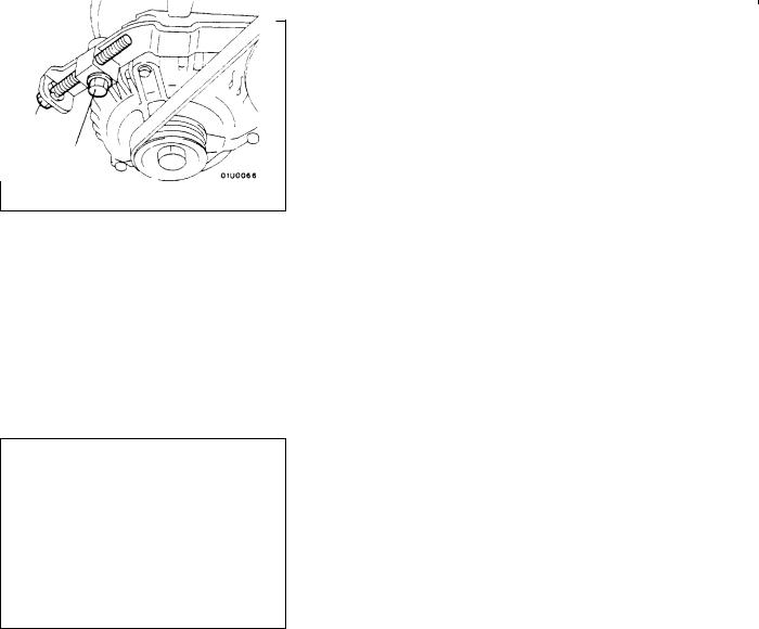
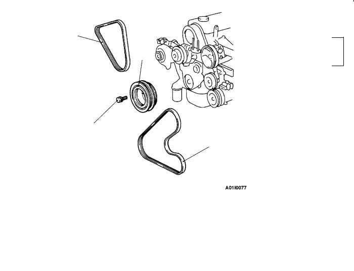
Alternator pulley |
Water pump |
|
pulley |
Crankshaft pulley
Adjusting bolt
Lock bolt
ON-VEHICLE SERVICE |
11100090432 |
DRIVE BELT TENSION CHECK AND ADJUSTMENT
ALTERNATOR DRIVE BELT TENSION CHECK
Use a belt tension gauge to check that the belt tension is at the standard value at a point half-way between the two pulleys as shown in the illustration. In addition, press this section with a force of 98 N and check that the amount of belt deflection is at the standard value.
Standard value:
Tension N |
294490 |
|
|
Deflection (Reference value) mm |
7.7- 12.3 |
|
|
ALTERNATOR DRIVE BELT TENSION ADJUSTMENT
1. |
Loosen the nut of the alternator pivot bolt. |
|||
2. |
Loosen the lock bolt. |
|
|
|
3. |
Use the adjusting bolt to adjust the belt tension and belt |
|||
|
|
deflection to the standard values. |
|
|
|
|
Standard value: |
|
|
|
|
|
|
|
|
|
Items |
When a used |
When a new |
|
|
|
belt is installed |
belt is installed |
|
|
|
|
|
|
|
Tension N |
343441 |
490686 |
|
|
|
|
|
|
|
Deflection (Reference |
8.4- 10.6 |
5.9- 7.7 |
|
|
value) mm |
|
|
|
|
|
|
|
4. |
Tighten the nut of the alternator pivot bolt. |
|||
|
|
Tightening torque: 44 Nm |
|
|
5. |
Tighten the lock bolt. |
|
|
|
|
|
Tightening torque: 22 Nm |
|
|
6. |
Tighten the adjusting bolt. |
|
||
Tightening torque: 10 Nm
ENGINE <4G6> - On-vehicle Service |
11A-7 |
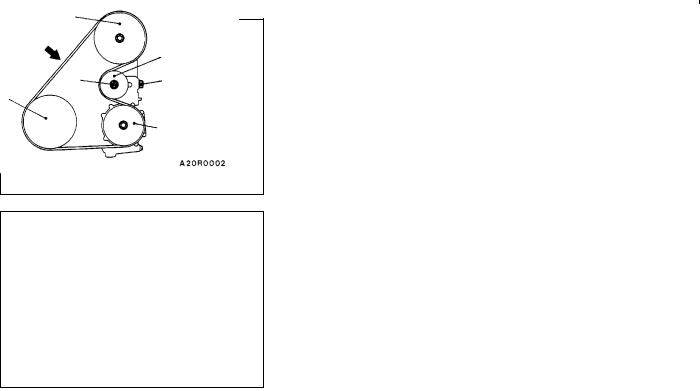
<Vehicles without A/C>
Oil pump pulley
98 N
B
A
Crankshaft pulley
Tensioner pulley
<Vehicles with A/C> |
|
|
Oil pump pulley |
|
|
98 N |
|
Tensioner |
|
|
|
|
|
pulley |
Crankshaft |
A |
B |
pulley |
|
|
A/C compressor pulley
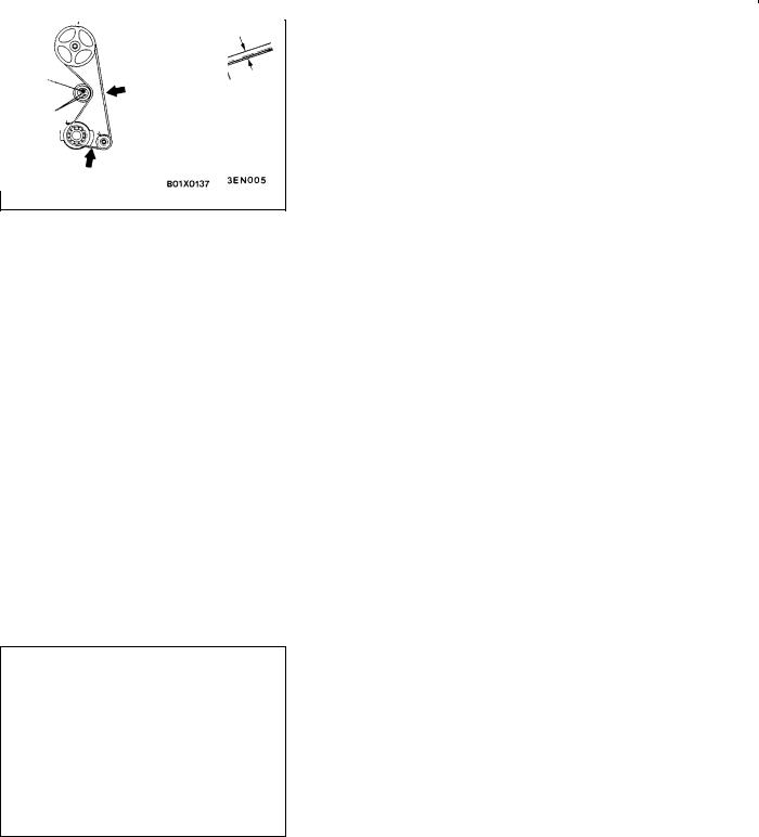
POWER STEERING OIL PUMP AND AIR CONDITIONER COMPRESSOR DRIVE BELT TENSION CHECK AND
ADJUSTMENT |
11100130127 |
1.Use a belt tension gauge to check that the belt tension is at the standard value at a point half-way between the
two pulleys (indicated by an arrow in the illustration). In addition, press this section with a force of 98 N and check that the amount of belt deflection is at the standard value.
Standard value:
Items |
When |
When a |
When a new |
|
checked |
used belt is |
belt is |
|
|
installed |
installed |
|
|
|
|
Tension N |
392588 |
441539 |
637833 |
|
|
|
|
Deflection |
11.7- 15.3 |
12.5- 14.3 |
8.8- 11.0 |
(Reference |
|
|
|
value) mm |
|
|
|
|
|
|
|
2.If the tension or deflection is outside the standard value, adjust by the following procedure.
(1)Loosen tensioner pulley fixing nut A.
(2)Adjust the amount of belt deflection using adjusting bolt B.
(3)Tighten fixing nut A.
Tightening torque: 25 Nm
(4)Check the belt deflection amount and tension, and readjust if necessary.
Caution
Check after turning the crankshaft once or more clockwise (right turn).
IGNITION TIMING CHECK |
11100170297 |
1.Before inspection, set the vehicle to the pre-inspection condition.
2.Connect the MUT-II to the diagnosis connector.
3.Set up a timing light.
4.Start the engine and run at idle.
5.Check that engine idle speed is within the standard value.
Standard value: 750 ± 100 r/min
6.Select No.17 of the MUT-II Actuator test.

11A-8 |
ENGINE <4G6> - On-vehicle Service |
7.Check that basic ignition timing is within the standard value.
Standard value: 5_ BTDC±2_
8.If the basic ignition timing is outside the standard value, inspect the MPI system while referring to GROUP 13A
-Troubleshooting.
9.Press the MUT-II clear key (Select a forced driving cancel mode) to release the Actuator test.
Caution
If the test is not cancelled, a forced driving will continue for 27 minutes. Driving under this condition may damage the engine.
10.Check that ignition timing is at the standard value.
Standard value: approx. 10_BTDC
NOTE
1.Ignition timing is variable within about ± 7_, even under normal operating.
2.And it is automatically further advanced by about 5_ from standard value at higher altitudes.
IDLE SPEED CHECK |
11100350066 |
1.Before inspection, set the vehicle to the pre-inspection condition.
2.Turn the ignition switch to OFF and connect the MUT-II to the diagnosis connector.
3.Check the basic ignition timing.
Standard value: 5_ BTDC±2_
4.Run the engine at idle for 2 minutes.
5.Check the idle speed. Select item No. 22 and take a reading of the idle speed.
Standard value: 750 ± 100 r/min
NOTE
The idle speed is controlled automatically by the idle speed control (ISC) system.
6.If the idle speed is outside the standard value, inspect the MPI components by referring to GROUP 13A - Troubleshooting.
IDLE MIXTURE CHECK |
11100210418 |
1.Before inspection, set the vehicle to the pre-inspection condition.
2.Turn the ignition switch to OFF and connect the MUT-II to the diagnosis connector.
3.Check that the basic ignition timing is within the standard value.
Standard value: 5_ BTDC±2_
4.Run the engine at 2,500 r/min for 2 minutes.

ENGINE <4G6> - On-vehicle Service |
11A-9 |
5.Set the CO, HC tester.
6.Check the CO contents and the HC contents at idle.
Standard value
CO contents: 0.5% or less
HC contents: 100 ppm or less
7.If there is a deviation from the standard value, check the following items:
D Diagnosis output
D Closed-loop control (When the closed-loop control is normal, the output signal of the oxygen sensor changes between 0 - 400 mV and 600 - 1,000 mV at idle.)
DFuel pressure
DInjector
DIgnition coil, spark plug cable, spark plug
DLeak in the EGR system and in the EGR valve
DEvaporative emission control system
DCompression pressure
NOTE
Replace the three way catalyst when the CO and HC contents are not within the standard value, even though the result of the inspection is normal on all items.
COMPRESSION PRESSURE CHECK |
11100260499 |
1.Before inspection, check that the engine oil, starter and battery are normal. In addition, set the vehicle to the pre-inspection condition.
2.Disconnect the spark plug cables.
3.Remove all of the spark plugs.
4.Disconnect the crank angle sensor connector.
NOTE
Doing this will prevent the engine-ECU from carrying out ignition and fuel injection.
5.Cover the spark plug hole with a shop towel etc., and after the engine has been cranked, check that no foreign material is adhering to the shop towel.
Caution
1.Keep away from the spark plug hole when cranking.
2.If compression is measured with water, oil, fuel, etc., that has come from cracks inside the cylinder, these materials will become heated and will gush out from the spark plug hole, which is dangerous.

11A-10 |
ENGINE <4G6> - On-vehicle Service |
Compression gauge
Vacuum gage
6.Set compression gauge to one of the spark plug holes.
7.Crank the engine with the throttle valve fully open and measure the compression pressure.
Standard value (at engine speed of 250 - 400 r/min): 1,400 kPa
Limit (at engine speed of 250 - 400 r/min): Min. 1,060 kPa
8.Measure the compression pressure for all the cylinders, and check that the pressure differences of the cylinders are below the limit.
Limit: Max. 100 kPa
9.If there is a cylinder with compression or a compression difference that is outside the limit, pour a small amount of engine oil through the spark plug hole, and repeat the operations in steps 7 and 8.
(1)If the compression increases after oil is added, the cause of the malfunction is a worn or damaged piston ring and/or cylinder inner surface.
(2)If the compression does not rise after oil is added, the cause is a burnt or defective valve seat, or pressure is leaking from the gasket.
10.Connect the crank angle sensor connector.
11.Install the spark plugs and spark plug cables.
12.Use the MUT-II to erase the diagnosis codes.
NOTE
This will erase the diagnosis code resulting from the crank angle sensor connector being disconnected.
MANIFOLD VACUUM CHECK |
11100270409 |
1.Start the engine and allow it to warm up until the temperature of the engine coolant reaches 80 to 95_C.
2.Connect a tachometer.
3.Attach a three-way union to the vacuum hose between the fuel pressure regulator and the air intake plenum, and connect a vacuum gauge.
4.Start the engine and check that idle speed is within standard value. Then read off the vacuum gauge.
Limit: Min. 69 kPa
ENGINE <4G6> - On-vehicle Service |
11A-11 |
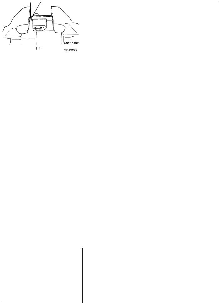
LASH ADJUSTER CHECK |
11100290344 |
If an abnormal noise (knocking) that seems to be coming from the lash adjuster is heard after starting the engine and does not stop, carry out the following check.
NOTE
(1)The abnormal noise which is caused by a problem with the lash adjusters is generated after the engine is started, and will vary according to the engine speed. However, this noise is not related to the actual engine load.
Because of this, if the noise does not occur immediately after the engine is started, if it does not change in accordance with the engine speed, or if it changes in accordance with the engine load, the source of the noise is not the lash adjusters.
(2)If there is a problem with the lash adjusters, the noise will almost never disappear, even if the engine has been run at idle to let it warm up.
The only case where the noise might disappear is if the oil in the engine has not been looked after properly and oil sludge has caused the lash adjusters to stick.
1.Start the engine.
2.Check that the noise occurs immediately after the engine is started, and that the noise changes in accordance with changes in the engine speed.
If the noise does not occur immediately after the engine is started, or if it does not change in accordance with the engine speed, the problem is not being caused y the lash adjusters, so check for some other cause of the problem. Moreover, if the noise does not change in accordance with the engine speed, the cause of the problem is probably not with the engine. (In these cases, the lash adjusters are normal.)
3.While the engine is idling, check that the noise level does not change when the engine load is varied (for example, by shifting from N ® D).
If the noise level changes, the cause of the noise is probably parts striking because of worn crankshaft bearings or connecting rod bearings. (In such cases, the lash adjusters are normal.)
4.After the engine has warmed up, run it at idle and check if any noise can be heard.
If the noise has become smaller or has disappeared, the cause of the noise was probably that oil sludge had caused the lash adjusters to become stuck. If this happens, carry out the following check. If the noise level does not change, go to step 5.
(1)Let the engine cool down sufficiently.
(2)Turn the crankshaft two full revolutions.

11A-12 |
ENGINE <4G6> - On-vehicle Service |
(3)Carry out lash adjuster simple check. (Refer to P.11A-13.)
D If any of the rocker arms can be pushed down easily during the lash adjuster simple check, replace the corresponding lash adjusters.
D If the lash adjuster simple check has been carried out but all lash adjusters are normal (if none of the rocker arms could be pushed down easily), check for some other cause of the problem.
NOTE
You can check whether the lash adjusters are normal or not by carrying out a leak-down test. (Refer to the Engine Workshop Manual.)
Caution
Make sure that the air has been fully bled before installation of a new lash adjuster. (Refer to the Engine Workshop Manual.)
5.Bleed the air from the lash adjusters. (Refer to P.11A-13.)
6.If the noise does not disappear even after the air has been bled from the lash adjusters, carry out the following check.
Carry out lash adjuster simple check. (Refer to P.11A-13.) D If one of the rocker arms can be pushed down easily during the lash adjuster simple check, replace the
corresponding lash adjuster.
D If two or more of the rocker arms can be pushed down easily during the lash adjuster simple check, the cause may be that the oil passage to the cylinder head is blocked.
Check for blockages in the oil passage, and clear the blockages if any are found. If there are no blockages, replace the lash adjusters.
D If the lash adjuster simple check has been carried out but all lash adjusters are normal (if none of the rocker arms could be pushed down easily), check for some other cause of the problem.
NOTE
You can check whether the lash adjusters are normal or not by carrying out a leak-down test. (Refer to the Engine Workshop Manual.)
Caution
Make sure that the air has been fully bled before installation of a new lash adjuster. (Refer to the Engine Workshop Manual.)
7.Start the engine and check that the abnormal noise has disappeared. If necessary, bleed the air from the lash adjusters. (Refer to P.11A-13.)
ENGINE <4G6> - On-vehicle Service |
11A-13 |
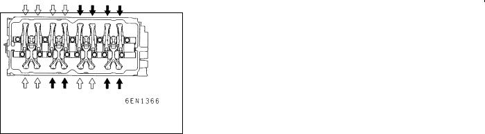
<LASH ADJUSTER SIMPLE CHECK>
1.Stop the engine.
2.Remove the rocker cover.
3.Set the No.1 cylinder to the compression top dead centre position.
4.Check the rocker arms indicated by white arrows in the illustration by the procedures given below.
<Checking an intake-side rocker arm>
Check whether the rocker arm moves downwards when the part of the rocker arm which touches the top of the lash adjuster is pushed.
D If the rocker arm moves down easily when it is pushed, make a note of which is the corresponding lash adjuster.
D If the rocker arm feels extremely stiff when it is pushed and does not move down, the lash adjuster is normal, so check for some other cause of the problem.
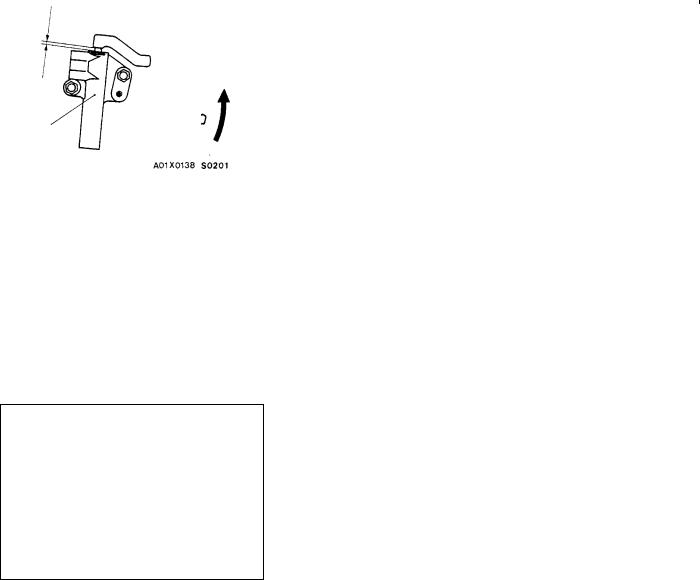
<Checking an exhaust-side rocker arm>
NOTE
It will not be possible to depress the Y-shaped rocker arm at the exhaust valve side if one lash adjuster is defective but the other one is normal. In such cases, carry out the following procedure using a thickness gauge.
(1)Check that a thickness gauge with a thickness of 0.1 - 0.2 mm can be inserted easily between the valve and the lash adjuster.
(2)If the thickness gauge can be inserted easily, make a note of which is the corresponding lash adjuster.
(3)If the thickness gauge cannot be inserted easily, the lash adjuster is normal, so check for some other cause of the problem.
5.Slowly turn the crankshaft 360_ in the clockwise direction.
6.Check the rocker arms indicated by black arrows in the illustration in the same way as explained in step 4.
<LASH ADJUSTER AIR BLEEDING>
NOTE
(1)If the vehicle is parked on a slope for a long period of time, the amount of oil inside the lash adjuster will decrease, and air may get into the high pressure chamber when starting the engine.
(2)After parking the vehicle for long periods, the oil drains out of the oil passage, and it takes time for the oil to be supplied to the lash adjuster, so air can get into the high pressure chamber.
(3)If either of the above situations occur, the abnormal noise can be eliminated by bleeding the air from inside the lash adjusters.
11A-14 |
ENGINE <4G6> - On-vehicle Service |
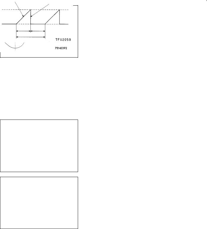
Good
High pressure chamber
Drive pattern for air bleeding
|
Gradually open the |
|
|
Close the throttle |
|
throttle valve. |
|
|
valve. |
|
Approx. |
|
|
|
|
|
|
|
|
3,000 r/min. |
|
|
|
|
Idle speed |
|
|
|
|
15 |
15 |
|
||
|
seconds |
seconds |
||
Once
1. Check the engine oil and replenish or replace the oil if necessary.
NOTE
(1)If there is a only small amount of oil, air will be drawn in through the oil screen and will get into the oil passage.
(2)If the amount of oil is greater than normal, then the oil will being mixed by the crankshaft and a large amount of air may get mixed into the oil.
(3)If the oil is degenerated, air and oil will not separate easily in oil, and the amount of air mixed into the oil will increase.
(4)If the air which has been mixed in with the oil due to any of the above reasons gets into the high pressure chamber of the lash adjuster, the air inside the high pressure chamber will be compressed when the valve is open and the lash adjuster will over-compress, resulting in abnormal noise when the valve closes. This is the same effect as if the valve clearance is adjusted to be too large by mistake. If the air inside the lash adjusters is then released, the operation of the lash adjusters will return to normal.
2.Run the engine at idle for 1 - 3 minutes to let it warm up.
3.With no load on the engine, repeat the drive pattern shown in the illustration at left and check if the abnormal noise disappears. (The noise should normally disappear after 10 - 30 repetitions, but if there is no change in the noise level after 30 repetitions or more, the problem is probably not due to air inside the lash adjusters.)
4.After the noise has disappeared, repeat the drive pattern shown in the illustration at left a further 5 times.
5.Run the engine at idle for 1 - 3 minutes and check that the noise has disappeared.
ENGINE <4G6> - Crankshaft Pulley |
11A-15 |
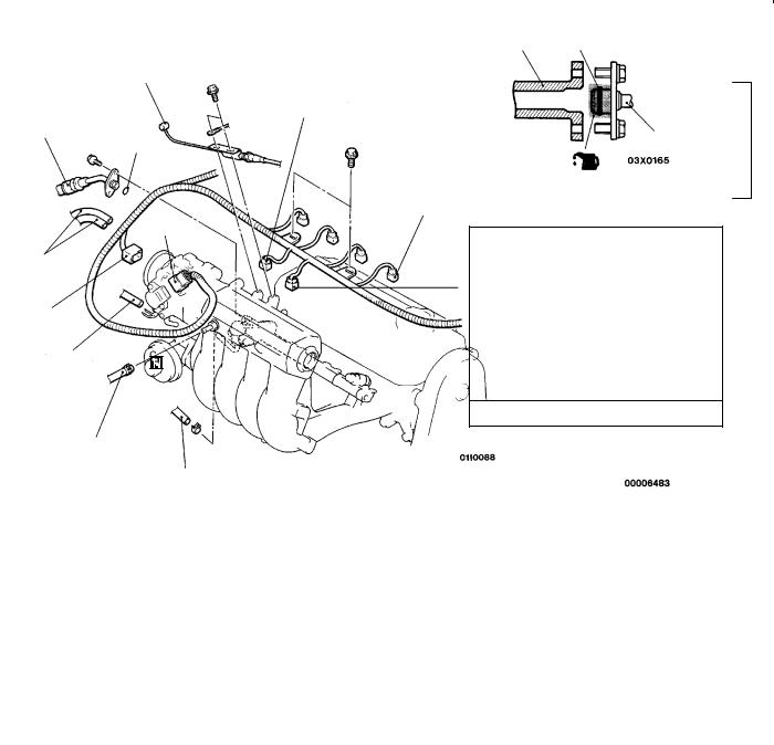
CRANKSHAFT PULLEY
REMOVAL AND INSTALLATION
Pre-removal Operation
DUnder Cover Removal
2
3
25 Nm
Removal steps
1.Drive belt (Power steering and A/C)
11200160303
Post-installation Operation
DDrive Belt Tension Adjustment (Refer to P.11A-6.)
DUnder Cover Installation
1
2.Drive belt (Alternator)
3.Crankshaft pulley

11A-16 ENGINE <4G6> - Camshaft and Camshaft Oil Seal
CAMSHAFT AND CAMSHAFT OIL SEAL |
11200190418 |
REMOVAL AND INSTALLATION
Pre-removal and Post-installation Operation
DAir Cleaner Removal and Installation
DTiming Belt Removal and Installation (Refer to P.11A-26.)
DRelay Box Removal and Installation
10 Nm
1 |
|
|
|
|
|
|
5 |
|
|
|
|
|
|
|
|
|
||
|
|
|
|
|
|
|
|
|
|
|
|
|
|
|
|
|||
|
|
|
|
|
|
2 |
|
|
|
|
|
|
|
|
|
|
|
|
|
|
|
|
|
|
|
|
|
|
|
|
|
|
|
|
|
|
|
|
|
|
|
|
|
4 |
|
|
|
|
|
|
(f 3 ± 1 mm) |
|
|
|
||
|
|
|
|
|
|
|
|
|
|
|
|
|
|
|
|
|
|
|
|
|
|
|
|
|
|
|
|
|
|
|
|
|
|
|
|||
|
|
|
|
|
|
|
|
|
|
|
|
|
|
|
|
|||
14 Nm |
|
|
|
|
3.4 Nm |
|
|
|
|
|
|
|
|
|
|
|
||
Sealant: |
|
|
|
|
|
|
|
|
||||||||||
|
|
|
|
|
|
|
|
|
|
|
|
|
|
|
|
|
||
|
|
|
|
|
|
|
|
|
|
|
|
|
|
|
|
|
||
|
|
|
|
|
|
|
|
|
MITSUBISHI GENUINE PART |
|||||||||
3 |
|
|
|
|
|
MD970389 or equivalent |
||||||||||||
|
|
|
|
|
|
|
|
|
|
|
|
|
|
|
||||
|
|
|
|
|
|
|
|
|
|
|
|
|
|
|
|
|||
|
|
22 Nm |
|
|
|
|
|
|
|
|
|
|
|
|
|
|
||
5 |
|
|
|
|
28 - 34 Nm |
|
|
|
|
|
8 |
|
|
|
|
|
|
|
|
|
|
|
|
|
|
|
|
|
|
|
|
|
|
|
|||
|
|
|
|
|
|
|
|
|
|
|
|
|
|
|
||||
|
|
|
|
|
|
|
|
|
|
|
|
|
Lip section |
|
||||
5 |
|
|
|
|
9 |
11 |
|
|
|
|
|
|
|
|
|
|
|
|
|
|
|
|
|
|
|
|
|
|
|
|
|
|
|
||||
|
|
|
|
|
|
|
|
|
|
|
|
|||||||
|
|
|
|
|
|
|
|
|
|
|
|
|
|
|
|
|||
|
|
|
|
|
|
|
|
|
|
|
|
|
|
|
|
|
|
|
6 |
|
|
|
|
10 |
|
|
|
|
|
|
|
|
|
|
|
||
12 |
|
|
|
|
|
|
|
|
|
|
|
|
|
|
|
|||
|
|
|
|
|
|
|
|
Cam section and |
|
|
|
|
||||||
|
|
|
|
|
|
|
|
|
|
|
|
|
||||||
|
|
|
|
|
|
|
88 Nm |
|
journal section |
|
||||||||
|
|
|
|
|
|
|
|
|
|
|
|
|
|
|
||||
12


 8
8
7
Engine oil
Removal steps |
|
|
|
1. |
Control harness connection |
"BA 8. |
Camshaft oil seal |
2. |
Spark plug cable |
9. |
Spark plug guide oil seal |
3. |
PCV hose connection |
AB" "AA 10. |
Rocker arm and shaft assembly |
4. |
Rocker cover |
|
(intake side) |
5. |
Camshaft position sensor support |
AB" "AA 11. |
Rocker arm and shaft assembly |
6. |
Camshaft position sensing cylinder |
|
(exhaust side) |
AA" "CA 7. Camshaft sprocket |
12. |
Camshaft |
|

ENGINE <4G6> - Camshaft and Camshaft Oil Seal |
11A-17 |
MB990767
MD998719 or
MD998754
MD998443
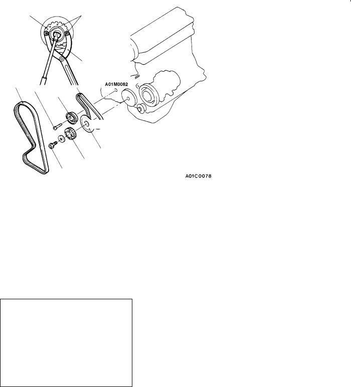
REMOVAL SERVICE POINTS
AA" CAMSHAFT SPROCKET REMOVAL
AB" ROCKER ARM AND SHAFT ASSEMBLY
REMOVAL
Before removing the rocker arm and shaft assembly, install the special tools as shown in the illustration so that the lash adjusters will not fall out.
INSTALLATION SERVICE POINTS
"AA ROCKER ARM AND SHAFT ASSEMBLY
INSTALLATION
1.Temporarily tighten the rocker shaft with the bolt so that all rocker arms on the inlet valve side do not push the valves.
2.Fit the rocker shaft spring from the above and position it so that it is right angles to the plug guide.
NOTE
Install the rocker shaft spring before installing the rocker arm and rocker arm shaft on the exhaust side.
3.Remove the special tool for fixing the lash adjuster.
4.Confirm that the rocker shaft notch is in the direction shown in the diagram.
11A-18 ENGINE <4G6> - Camshaft and Camshaft Oil Seal
"BA CAMSHAFT OIL SEAL INSTALLATION
1.Apply engine oil to the camshaft oil seal lip.
2.Use the special tool to press-fit the camshaft oil seal.
MD998713
"CA CAMSHAFT SPROCKET INSTALLATION
Use the special tool to stop the camshaft sprocket from turning in the same way as was done during removal, and then tighten the bolts to the specified torque.
|
ENGINE <4G6> - Oil Pan |
11A-19 |
||
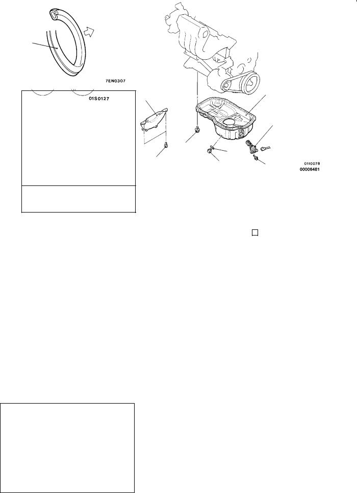
OIL PAN |
|
11200280207 |
||
REMOVAL AND INSTALLATION |
|
|
|
|
|
|
|
|
|
|
Pre-removal and Post-installation Operation |
D Front Exhaust Pipe Removal and Installation (Refer |
|
|
|
D Engine Oil Draining and Supplying (Refer to GROUP |
|
||
|
12 - On-vehicle Service.) |
to GROUP 15.) |
|
|
|
D Oil Level Gauge Removal and Installation |
|
|
|
|
|
|
|
|
5
f 4 ± 1 mm
Groove |
Bolt |
|
hole |
||
|
Sealant:
MITSUBISHI GENUINE PART MD970389 or equivalent
Removal steps
1. |
Drain plug |
|
"AA 2. |
Drain plug gasket |
|
3. |
Bell housing cover |
|
|
|
|
MD998727 |
|
MD998727 |
|
|
|
5
3
4
7 Nm
9 Nm |
1 |
2 |
|
9 Nm |
|
||||
|
|
|||
|
|
|
|
|
|
4. |
Oil level sensor |
||
AA" |
5. |
Oil pan |
||
REMOVAL SERVICE POINT
AA" OIL PAN REMOVAL
After removing the oil pan mounting bolts, remove the oil pan with the special tool and a brass bar.
Caution
Perform this slowly to avoid deformation of the oil pan flange.
Oil pan side
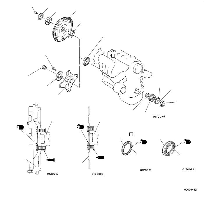
Drain plug gasket
INSTALLATION SERVICE POINT
"AA DRAIN PLUG GASKET INSTALLATION
Install the drain plug gasket in the direction so that it faces as shown in the illustration.
11A-20 |
ENGINE <4G6> - Crankshaft Oil Seal |
CRANKSHAFT OIL SEAL |
|
|
|
|
|
|
|
|
|
|
11200310135 |
|||||||||||||||
REMOVAL AND INSTALLATION |
|
|
|
|
|
|
|
|
|
|
|
|
|
|
||||||||||||
|
|
|
|
|
|
|
|
|
|
|
|
|
|
|
|
|
|
|
|
|
|
|
|
|
|
|
|
|
|
127 - 137 Nm |
7 |
|
<M/T> |
|
|
|
|
|
|
|
|
|
|
|
|
|
|
||||||
|
|
|
|
|
|
|
|
|
|
|
|
|
|
|
|
|
|
|
|
|
|
|||||
|
|
|
|
|
|
|
9 |
|
|
|
|
|
|
|
|
|
|
|
||||||||
|
|
|
|
|
|
8 |
|
|
|
|
|
|
|
|
|
|
|
|
|
|
|
|||||
|
|
|
|
|
|
|
|
|
|
|
|
|
11 |
|
|
|
|
|
|
|
|
|
|
|||
|
|
|
|
|
127 - 137 Nm |
12 |
|
|
|
|
|
|
|
|
|
|
||||||||||
|
|
|
|
|
|
|
|
|
|
|
|
|
|
|
||||||||||||
|
|
|
|
|
|
|
|
|
|
|
|
|
|
|
|
|
|
|
||||||||
|
|
|
|
|
|
|
|
|
|
|
|
|
|
|
|
|
|
|
|
|
|
|
|
|
|
|
|
|
|
|
|
|
|
|
|
<A/T> |
|
|
|
|
|
|
|
|
|
|
|
|
|
|
|||
6 |
|
|
|
|
|
|
|
|
|
|
|
|
|
|
|
|
|
|
|
2 |
|
|
|
|||
|
|
|
|
|
|
|
|
|
|
|
|
|
|
|
|
|
|
|
|
|
|
|||||
|
|
|
|
|
|
|
|
|
|
|
|
|
|
|
|
|
|
|
|
|
|
|
|
|
|
|
|
|
|
|
|
|
8 |
|
|
|
|
|
|
|
|
|
|
|
|
|
|
|
|
4 |
|
|
|
|
|
|
|
|
|
|
|
|
|
|
|
|
|
|
|
|
|
|
|
|
|
|
|
|
|
|
|
|
|
|
|
|
10 |
|
|
|
|
|
|
|
|
|
|
|
|
|
1 |
|
|
||||
|
|
|
|
|
|
|
|
|
|
|
|
|
|
|
|
|
|
|
|
|
|
|
|
|
||
|
|
|
|
|
|
|
|
|
|
|
|
|
|
|
|
|
|
|
|
|
|
|
|
|
||
|
|
|
<M/T> |
|
|
|
|
|
<A/T> |
|
|
|
|
|
|
|
5 |
3 |
|
|
|
|
|
|||
|
|
|
|
|
|
|
|
|
|
|
|
|
|
|
|
|
|
|
|
|
|
|
|
|
||
|
|
|
|
|
|
|
|
|
|
|
|
|
|
|
|
|
|
|
|
|
|
|
|
|
|
|
|
|
|
|
|
|
|
Crankshaft |
|
|
|
|
Crankshaft |
|
|
|
|
|
|
|
|
|
|
||||
|
|
|
|
|
|
|
|
|
|
|
|
|
|
|
|
|
|
|
|
|
|
|
|
|
|
|
|
|
|
|
|
|
|
|
|
|
|
|
|
|
|
|
|
|
|
|
|
|
|
|
|
|
|
|
|
|
|
|
|
|
|
|
|
|
(Engine oil: |
|
|
12 |
|
|
|
|
5 |
|
|
|
||||
|
|
|
|
|
|
|
|
|
|
|
bolt washer |
|
|
|
|
|
|
|
|
|
||||||
|
|
(Engine oil: |
|
|
|
|
|
|
surface) |
|
|
|
|
|
|
|
|
|
|
|
|
|
|
|||
|
|
bolt wash- |
|
|
|
|
|
|
|
|
|
|
|
|
|
|
|
|
|
|
|
|
|
|
||
|
|
|
|
|
|
|
|
|
|
|
|
|
|
|
|
|
|
|
|
|
|
|
|
|||
|
|
er surface) |
|
|
|
|
|
|
|
|
|
|
|
|
|
|
|
|
|
|
|
|
|
|
||
|
|
|
|
|
|
|
|
|
|
|
|
|
|
|
|
|
|
|
|
|
|
|
|
|
|
|
|
|
|
|
|
|
|
|
|
|
|
|
|
|
|
|
|
|
|
|
|
|
|
||||
|
9 |
|
|
|
|
|
|
|
|
|
|
|
|
|
|
|
|
|
|
|
|
Lip section |
|
|
||
|
|
|
|
|
|
|
|
|
|
|
|
|
|
|
|
|
|
Lip section |
|
|
||||||
|
|
|
|
|
|
|
|
|
|
|
|
|
10 |
|
|
|
|
|
|
|
|
|
|
|||
|
|
|
|
|
|
|
|
|
|
|
|
|
|
|
|
|
|
|
|
|
|
|
||||
|
|
|
|
|
|
|
|
|
|
|
|
|
|
|
|
|
|
|
|
|
|
|
||||
|
Sealant: 3M Stud locking 4170 or equivalent |
|
Engine oil |
|
|
|
|
|
|
|||||||||||||||||
|
|
|
|
|
|
|
|
|
|
|
|
|
|
|
|
|
|
|
|
|
|
|
|
|
|
|
Crankshaft front oil seal removal steps
DTiming belt (Refer to P.11A-26.)
DCrank angle sensor (Refer to GROUP 16.)
1.Crankshaft sprocket
2.Flange
3.Crankshaft sprocket B
4.Key
"CA 5. Crankshaft front oil seal
Crankshaft rear oil seal removal steps
DOil pan (Refer to P.11A-19.) AA" D Transmission assembly
DClutch cover and disc <M/T>
6.Crankshaft bushing
AB" "BA 7. Plate <M/T> AB" "BA 8. Adapter plate AB" "BA 9. Flywheel <M/T> AB" "BA 10. Drive plate <A/T>
AB" "BA 11. Adapter plate <M/T> "AA 12. Crankshaft rear oil seal
ENGINE <4G6> - Crankshaft Oil Seal |
11A-21 |
<M/T>
Flywheel
Bolt
MD998781
Crankshaft |
|
rear oil seal |
Crankshaft |
|
|
MD990938 |
|
MD998776
REMOVAL SERVICE POINTS
AA" TRANSMISSION ASSEMBLY REMOVAL
<M/T>:
Refer to GROUP 22.
Caution
Do not remove the flywheel mounting bolt shown by the arrow. If this bolt Is removed, the flywheel will become out of balance and damaged.
<A/T>:
Refer to GROUP 23.
AB" PLATE <M/T>/ADAPTER PLATE/FLYWHEEL
<M/T>/DRIVE PLATE <A/T> REMOVAL
Use the special tool to secure the flywheel or drive plate, and remove the bolts.
INSTALLATION SERVICE POINTS
"AA CRANKSHAFT REAR OIL SEAL INSTALLATION
1.Apply a small mount of engine oil to the entire circumference of the oil seal lip.
2.Install the oil seal by tapping it as far as the chamfered position of the oil seal case as shown in the illustration.
"BA DRIVE PLATE <A/T>/FLYWHEEL <M/T>/ADAPTER
PLATE/PLATE <M/T> INSTALLATION
1.Clean off all sealant, oil and other substances which are adhering to the threaded bolts, crankshaft thread holes and the flywheel or drive plate.
2.Apply oil to the bearing surface of the flywheel or drive plate bolts.
3.Apply oil to the crankshaft thread holes.
4.Apply sealant to the threaded mounting holes.
Specified sealant: 3M Stud locking 4170 or equivalent
5.Use the special tool to hold the flywheel or drive plate in the same manner as removal, and install the bolt.
"CA CRANKSHAFT FRONT OIL SEAL INSTALLATION
1.Apply a small amount of engine oil to the entire circumference of the oil seal lip.
2.Press-fit the oil seal unit it is flush with the oil seal case.
11A-22 |
ENGINE <4G6> - Cylinder Head Gasket |
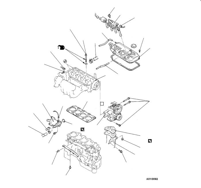
CYLINDER HEAD GASKET
REMOVAL AND INSTALLATION
Pre-removal Operation
DFuel Discharge Prevention (Refer to GROUP 13A
-On-vehicle Service.)
DEngine Oil Draining (Refer to GROUP 12 - On-vehicle Service.)
DThermostat Case Assembly Removal (Refer to GROUP 14 - Water Hose and Water Pipe.)
1
9
10
5
2
6
4
3
11
Removal steps
1.Accelerator cable connection
2.Vacuum hose connection
3.Brake booster vacuum hose connection
4.Vacuum hose connection
5.Throttle position sensor connector
6.Idle speed control connector
11200400542
Post-installation Operation
DThermostat Case Assembly Installation (Refer to GROUP 14 - Water Hose and Water Pipe.)
DEngine Oil Supplying (Refer to GROUP 12 - On-vehicle Service.)
DAccelerator Cable Adjustment (Refer to GROUP 17 - On-vehicle Service.)
Delivery pipe |
|
O-ring |
10
7Engine oil
8
7.Injector connector
8.Purge control solenoid valve connector
9.EGR solenoid valve connector
"CA 10. High-pressure fuel hose connection 11. Fuel return hose connection
|
ENGINE <4G6> - Cylinder Head Gasket |
11A-23 |
|
10 Nm |
|
|
15 |
|
<Cold engine> |
14 |
|
78 Nm ® 0 Nm ® 20 Nm ® + 90_ ® + 90_
16
|
|
27 |
|
3.4 Nm |
|
|
|
12 |
|
|
|
|
|
|
|
|
|
|
(Engine oil) |
|
|||
|
|
26 |
|||
17 |
|
|
|||
|
|
||||
|
|
|
|
|
|
19
28 13
22 |
18 |
29 |
|
49 Nm |
|
|
|||
|
|
|
|
20
21
24
24 Nm
|
|
|
|
|
44 Nm |
|
|
|
|
|
25 |
|
23 |
|
|
34 Nm |
|
|
|
|
|
|
|
|
|
|
|
|
|
|
|
31 Nm |
|
|
|
|
|
|
|
21. |
Heater hose connection |
12. |
Radiator upper hose connection |
|
|||
13. |
PCV hose |
|
22. |
Thermostat case assembly |
|
14. |
Ignition coil connector |
|
23. |
Water hose connection |
|
15. |
Ignition coil assembly |
AA" |
24. |
Power steering oil pump and |
|
16. |
Breather hose |
|
|
bracket assembly |
|
17. |
Engine coolant temperature sensor |
|
25. |
Front exhaust pipe connection |
|
|
connector |
|
26. |
Rocker cover |
|
18. |
Engine coolant temperature gauge |
|
D |
Timing belt (Refer to P.11A-26.) |
|
|
unit connector |
AB" "BA 27. |
Cylinder head bolt |
||
19. |
Camshaft position sensor |
|
28. |
Cylinder head assembly |
|
20. |
Water hose connection |
|
"AA 29. |
Cylinder head gasket |
|
11A-24 |
ENGINE <4G6> - Cylinder Head Gasket |
Intake side |
|
Front of engine |
|
|
|
|
|
||
3 |
5 |
10 |
8 |
2 |
1 |
7 |
9 |
6 |
4 |
Exhaust side |
|
|
|
|
|
|
|
|
|
|
Burred side |
Head bolt |
|
|
|
||
|
Head bolt |
(Engine |
|
|
oil) |
||
A |
washer |
||
|
|||
|
|
||
|
Cylinder |
|
|
|
head |
|
|
|
|
|
REMOVAL SERVICE POINTS
AA" POWER STEERING OIL PUMP AND BRACKET
ASSEMBLY REMOVAL
Remove the power steering oil pump and bracket assembly from the engine with the hose attached.
NOTE
Place the removed power steering oil pump in a place where it will not be a hindrance when removing and installing the cylinder head assembly, and tie it with a cord.
AB" CYLINDER HEAD BOLT REMOVAL
Loosen the bolts in 2 or 3 steps in order of the numbers shown in the illustration, and remove the cylinder head assembly.
Caution
Because the plug guides cannot be replaced by themselves, be careful not to damage or deform the plug guides when removing the cylinder head bolts.
INSTALLATION SERVICE POINTS
"AA CYLINDER HEAD GASKET INSTALLATION
1.Wipe off all oil and grease from the gasket mounting surface.
2.Install so that the shapes of the cylinder head holes match the shapes of the respective cylinder head gasket holes.
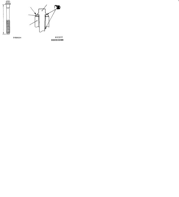
"BA CYLINDER HEAD BOLT INSTALLATION
1.When installing the cylinder head bolts, the length below the head of the bolts should be within the limit.
If it is outside the limit, replace the bolts.
Limit (A): 99.4 mm
2.The head bolt washer should be installed with the burred side caused by tapping out facing upwards.
3.Apply a small amount of engine oil to the thread section and the washer of the cylinder head bolt.

ENGINE <4G6> - Cylinder Head Gasket |
11A-25 |
Intake side |
|
Front of engine |
|
|
|
|
|
||
8 |
6 |
1 |
3 |
9 |
10 |
4 |
2 |
5 |
7 |
Exhaust side |
|
|
|
|
|
|
|
|
|
|
|
|
|
|
Step 4 |
|
|
Step 5 |
|
90_ |
|
|
|
90_ |
Painted mark |
|
Painted mark |
||
|
|
|
|
|
4. Tighten the bolts by the following procedure.
Step |
Operation |
Remarks |
|
|
|
1 |
Tighten to 78 Nm. |
Carry out in the order |
|
|
shown in the illustration. |
|
|
|
2 |
Fully loosen. |
Carry out in the reverse |
|
|
order of that shown in the |
|
|
illustration. |
|
|
|
3 |
Tighten to 20 Nm. |
Carry out in the order |
|
|
shown in the illustration. |
|
|
|
4 |
Tighten 90_ of a turn. |
In the order shown in the |
|
|
illustration. Mark the head |
|
|
of the cylinder head bolt |
|
|
and cylinder head by paint. |
|
|
|
5 |
Tighten 90_ of a turn. |
In the order shown in the |
|
|
illustration. Check that the |
|
|
painted mark of the head |
|
|
bolt is lined up with that of |
|
|
the cylinder head. |
|
|
|
Caution
1.Always make a tightening angle just 90_. If it is less than 90_, the head bolt will be loosened.
2.If it is more than 90_, remove the head bolt and repeat the procedure from step 1.
"CA HIGH-PRESSURE FUEL HOSE INSTALLATION
1.Apply a small amount of new engine oil to the O-ring.
Caution
Do not let any engine oil get into the delivery pipe.
2.While turning the high-pressure fuel hose to the right and left, install the delivery pipe, while being careful not to damage the O-ring. After installing, check that the hose turns smoothly.
3.If the hose does not turn smoothly, the O-ring is probably being clamped. Disconnect the high-pressure fuel hose and check the O-ring for damage. After this, re-insert the delivery pipe and check that the hose turns smoothly.
11A-26 |
ENGINE <4G6> - Timing Belt |
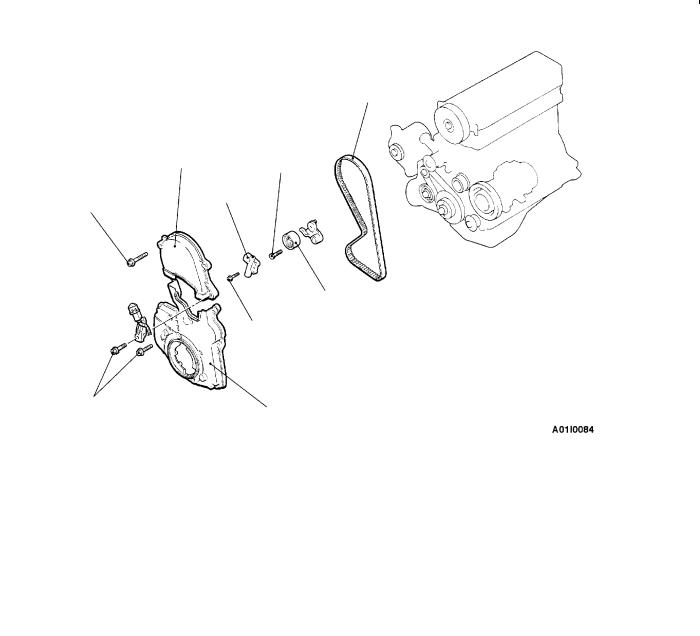
TIMING BELT |
11200430473 |
REMOVAL AND INSTALLATION
Pre-removal and Post-installation Operation
DCrankshaft Pulley Removal and Installation (Refer to P.11A-15.)
DEngine Mount Bracket Removal and Installation (Refer to GROUP 32 - Engine Mounting.)
3
1
48 Nm
5
10 - 12 Nm
4
24 Nm
9 Nm
2
Removal steps
1.Timing belt upper cover
2.Timing belt lower cover
"CA D Timing belt tension adjustment AA" "BA 3. Timing belt
4. Tension pulley "AA 5. Auto tensioner
ENGINE <4G6> - Timing Belt |
11A-27 |
|
Timing mark (Top |
Timing mark |
|||||||
|
of cylinder head) |
Camshaft sprocket |
|||||||
|
|
Timing mark |
Timing mark |
||||||
|
|
|
|
|
|
|
|
||
|
Timing mark |
Oil pump |
|||||||
|
Crankshaft |
sprocket |
|||||||
|
|
|
|
|
|
|
|||
|
sprocket |
|
|
|
|
|
|
||
|
|
|
|
|
|
|
|
|
|
|
|
|
|
|
|
|
|
|
|
|
|
|
|
|
|
|
|
|
|
|
|
|
|
|
|
Centre bolt |
|||
|
|
|
|
|
|
|
|
|
|
|
|
|
|
|
|
|
|
|
|
|
|
|
|
|
|
|
|
||
|
|
|
98N - 196N |
||||||
|
|
B |
|
|
|
|
|
||
|
A |
|
|
|
Movement |
|
|||
|
|
|
|
|
|
|
|
|
|
|
|
|
|
|
|
||||
|
|
|
|
|
Push rod |
|
|||
|
Auto tensioner |
|
|
|
|
|
|
|
|
|
|
|
|
|
|
||||
|
|
|
|
|
|
|
|
|
|
|
|
|
|
|
|
|
|
|
|
A B
REMOVAL SERVICE POINT
AA" TIMING BELT REMOVAL
1.Turn the crankshaft clockwise (right turn) to align each timing mark and to set the No. 1 cylinder at compression top dead centre.
Caution
The crankshaft should always be turned only clockwise.
2.Loosen the tension pulley centre bolt.
3.Move the tension pulley to the water pump side, and then remove the timing belt.
Caution
If the timing belt is to be re-used, use chalk to mark (on its flat side) an arrow indicating the clockwise direction.
INSTALLATION SERVICE POINTS
"AA AUTO TENSIONER INSTALLATION
1.Apply 98 - 196 N force to the auto tensioner by pressing it against a metal (cylinder block, etc.), and measure the movement of the push rod.
Standard value: Within 1 mm
A:Length when it is free (not pressed)
B:Length when it is pressed
A - B: Movement
2. If it is out of the standard value, replace the auto tensioner.
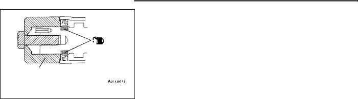
3.Use a press or vice to gently compress the auto tensioner push rod until pin hole A of the push rod and pin hole B of the tensioner cylinder are aligned.
Caution
If the compression speed is too fast, the rod may become damaged, so be sure to carry out this operation slowly.
11A-28 |
ENGINE <4G6> - Timing Belt |
Set pin
Timing mark (Top |
|
Timing mark |
||
of cylinder head) |
|
Camshaft sprocket |
||
Timing mark |
Timing mark |
|||
|
|
|
||
Timing mark |
|
|
Oil pump |
|
Crankshaft |
|
|
sprocket |
|
|
|
|
|
|
sprocket |
|
|
|
|
|
|
|
|
|
|
|
|
|
|
|
|
60 mm or |
8 mm |
|
Plug |
|
more |
|
|
|
|
|
|
|
|
|
|
|
Screwdriver |
|
Counter- |
|
|
|
|
balance |
|
Cylinder |
|
|
shaft |
|
||
|
|
block |
||
|
|
|
|
|
|
|
|
|
|
Fixing bolt
Belt tension side
Pin hole
Belt tension side
4.Once the holes are aligned, insert the set pin.
NOTE
When replacing the auto tensioner with a new part, the pin will be in the auto tensioner.
5.Install the auto tensioner to the engine.
"BA TIMING BELT INSTALLATION
1.Align the timing marks on the camshaft sprocket, crankshaft sprocket and oil pump sprocket.
2.After aligning the timing mark on the oil pump sprocket, remove the cylinder block plug and insert a Phillips screwdriver with a diameter of 8 mm, and check to be sure that the screwdriver goes in 60 mm or more. If the screwdriver will only go in 20 - 25 mm before striking the counterbalance shaft, turn the sprocket once, realign the timing mark and check that the screwdriver goes in 60 mm or more. The screwdriver should not be taken out until the timing belt is installed.
3.Install the belt to the crankshaft sprocket, oil pump sprocket and camshaft sprocket in that order, so that there is no slackness in the belt tension.
Caution
If the timing belt is re-used, install so that the arrow marked on it at time of removal is pointing in the clockwise direction.
4.Set the tension pulley so that the pin holes are at the top, press the tension pulley lightly against the timing belt, and then provisionally tighten the fixing bolt.
5.Adjust the timing belt tension.
ENGINE <4G6> - Timing Belt |
11A-29 |
|
|
|
|
|
|
|
50 Nm |
|
|
|
|
|
|
Tension |
|
|
|
|
|
|
|
|
|
direction |
|
MD998767 |
|
||
|
|
|
||
|
|
|
|
|
|
|
|
|
|
A
Auto tensioner
"CA TIMING BELT TENSION ADJUSTMENT
1.After turning the crankshaft 1/4 of a revolution in the anticlockwise direction, turn it in the clockwise direction until the timing marks are aligned.
2.Loosen the tension pulley fixing bolt, and then use the special tool and a torque wrench to tighten the fixing bolt to the specified torque while applying tension to the timing belt.
Standard value: 3.5 Nm <Timing belt tension torque>
Caution
When tightening the fixing bolt, make sure that the tension pulley does not turn with the bolt.
3.Turn the crankshaft two revolutions in the clockwise direction so that the timing marks are aligned. After leaving it for 15 minutes, measure the amount of protrusion of the auto tensioner.
Standard value (A): 3.8 - 4.5 mm
4.If the amount of protrusion is outside the standard value, repeat the operation in steps (1) to (3).
5.Check again to be sure that the timing marks of each sprocket are aligned.
11A-30 |
ENGINE <4G6> - Timing Belt B |
TIMING BELT B |
11200460106 |
REMOVAL AND INSTALLATION
5
1
19 Nm
4
3
2
|
|
|
108 - 127 Nm |
|
|
|
|
Removal steps |
|
|
|
||
|
1. |
Timing belt (Refer to P.11A-26.) |
4. |
Timing belt B |
tensioner |
|
AA" "CA |
2. |
Crankshaft sprocket |
AB" "AA 5. |
Timing belt B |
|
|
"BA |
3. |
Flange |
|
|
|
|
Crankshaft |
MD998719 or MD998754 |
sprocket |
MB990767
REMOVAL SERVICE POINTS
AA" CRANKSHAFT SPROCKET REMOVAL
AB" TIMING BELT B REMOVAL
Caution
If timing belt “B” is to be re-used, use chalk to mark it with an arrow on its flat side indicating the turning direction (to the right).
 Loading...