


35A
Table of contents
 Loading...
35A-1
SERVICE BRAKES
CONTENTS
BASIC BRAKE SYSTEM 35A.........................................
ANTI-SKID BRAKING SYSTEM (ABS) <2WD> 35B......................
ANTI-SKID BRAKING SYSTEM (ABS) <4WD> 35C......................
NOTE
THE GROUPS MARKED BY ARE NOT IN THIS MANUAL
35109000159

35A-2
BASIC BRAKE
SYSTEM
CONTENTS
GENERAL INFORMATION 3..................
SERVICE SPECIFICATIONS 4.................
LUBRICANTS 5..............................
SEALANTS 5................................
SPECIAL TOOLS 5..........................
ON-VEHICLE SERVICE 6.....................
Brake Pedal Check and Adjustment 6...........
Stop Lamp Switch Check 7.....................
Brake Booster Operating Test 7.................
Check Valve Operation Check 8.................
Proportioning Valve Function Test 9.............
Brake Fluid Level Sensor Check 9..............
Bleeding 10....................................
35109000302
Disc Brake Pad Check and Replacement 10.....
Disc Brake Rotor Check 12.....................
Brake Lining Thickness Check 14...............
Brake Drum Inside Diameter Check 14..........
Brake Lining and Brake Drum Connection
Check 14......................................
BRAKE PEDAL 15.......................... MASTER CYLINDER AND BRAKE
BOOSTER 16...............................
Master Cylinder 18.............................
DISC BRAKE 19............................
REAR DRUM BRAKE 24....................
Wheel Cylinder 26.............................
PROPORTIONING VALVE 28.................
BASIC BRAKE SYSTEM -
General Information
35A-3
GENERAL INFORMATION
35100010182
The brake system offers high dependability and durability along with improved braking performance and
brake sensitivity.
Items Specifications
Master cylinder Type Tandem type (with level sensor)
I.D. mm 23.8
Brake booster Type Vacuum type, single
Effective dia. of power cylinder mm 230
Boosting ratio 6.0
Proportioning valve Type Dual type
Decompression ratio 0.25
Front brakes Type Floating caliper, 1-piston, ventilated disc
Disc effective dia.´thickness mm 256´24
Wheel cylinder I.D. mm 60.3
Pad thickness mm 10.0
Clearance adjustment Automatic
Rear disc brakes Type Floating caliper, 1-piston, solid disc
Disc effective dia.´thickness mm 262´24
Wheel cylinder I.D. mm 34.9
Pad thickness mm 10.0
Clearance adjustment Automatic
Rear drum brakes Type Leading trailing
Drum I.D. mm 203
Wheel cylinder I.D. mm 20.6
Lining thickness mm 4.4
Clearance adjustment Automatic
Brake fluid DOT3 or DOT4
35A-4
BASIC BRAKE SYSTEM -
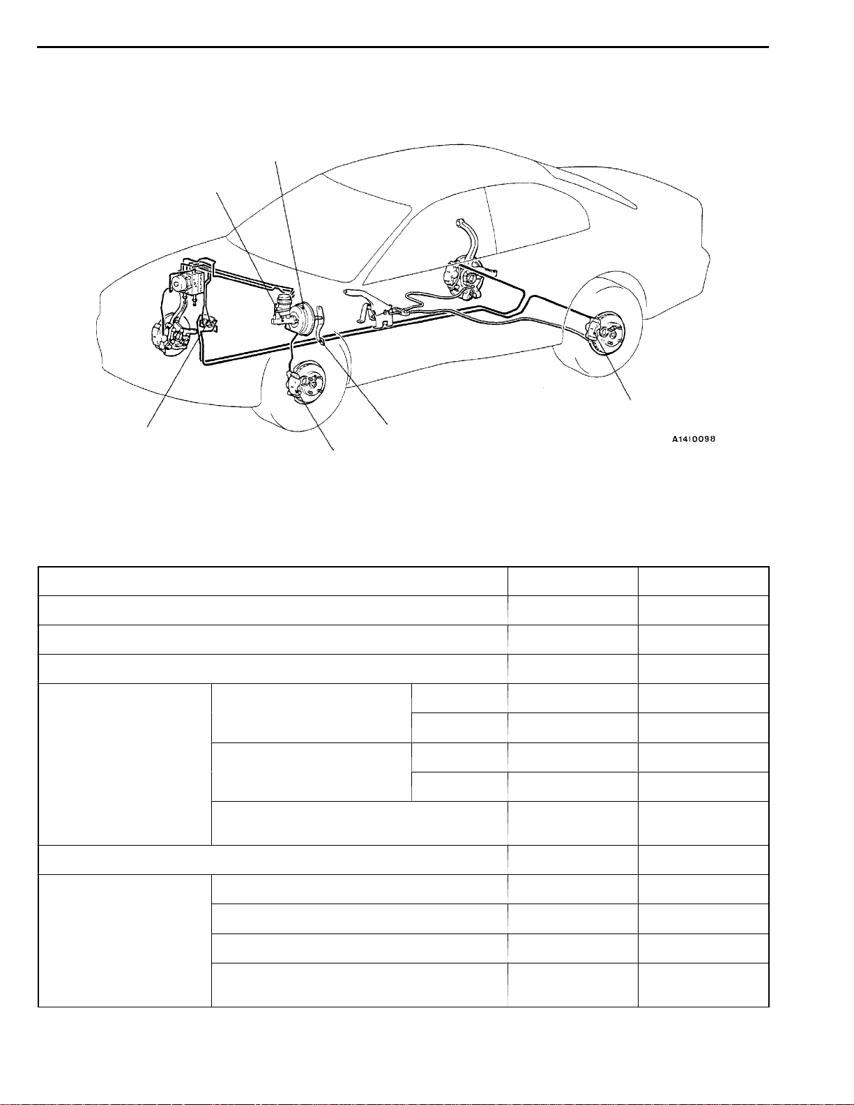
CONSTRUCTION DIAGRAM
Brake booster
Master cylinder
General Information/
ServiceSpecifications
Rear brake
Proportioningvalve
Front brake
Brake pedal
SERVICE SPECIFICATIONS
Items Standard value Limit
Brake pedal height mm 162.8 - 165.8 Brake pedal free play mm 3-8 Brake pedal to floor board clearance mm 90 or more Proportioning valve Split point MPa Sedan 2.94±0.25 -
Wagon 3.43±0.25 -
Output fluid pressure Sedan 4.66±0.39 (9.81) (Input fluid pressure) MPa
Wagon 5.80±0.39 (9.81) -
Output fluid pressure difference between left
and right MPa
- 0.39
35100030201
Brake booster push rod protruding length mm 9.65 -9.90 Front disc brake Pad thickness mm 10.0 2.0
Disc thickness mm 24.0 22.4
Disc runout mm - 0.06
Dragforce (tangential forceof wheelmounting
bolts) N
69 or less -
Service Specifications/Lubricants/
BASIC BRAKE SYSTEM -
Items Standard value Limit
Rear disc brake Pad thickness mm 10.0 2.0
Disc thickness mm 10.0 8.4
Disc runout mm - 0.08
Sealants/Special Tools
35A-5
Drag force (tangential force of wheel mounting
bolts) N
Rear drum brake Lining thickness mm 4.4 1.0
Drum inside diameter mm 203 205
69 or less -
LUBRICANTS
Items Specified Lubricant
Brake fluid DOT3 or DOT4
Brake piston seal Repair kit grease (orange)
Slide pin boot and slide pin bush inner surfaces
Brake piston boot inner surfaces
Piston boot mounting grooves
Rear brake shoe and backing plate contact surfaces Brake grease SAE J310, NLGI No.1
Shoe assembly and auto adjuster assembly contact
surfaces
Shoe and lever assembly and auto adjuster assembly
contact surfaces
35100040082
SEALANTS
Items Specified sealant Remarks
Thread part fitting 3M ATD Part No. 8661 or equivalent Semi-drying sealant
V acuum switch
SPECIAL TOOLS
Tool Number Name Use
MB990964
MB990520
MB990619
MB990998 Front hub remover
Brake tool set D Pushing-in of the disc brake piston
D Installation of drum brake wheel cylinder
piston cup
Provisional holding of the wheel bearing
and installer
35100050153
35100060071
35A-6
BASIC BRAKE SYSTEM -
On-vehicle Service
Operating
rod
Operating
rod lock nut
Pedal down
Pedal up
Lock nut
Stop lamp
switch
Lock nut
Outer case
0.5 - 1.0 mm
ON-VEHICLE SERVICE
35100090186
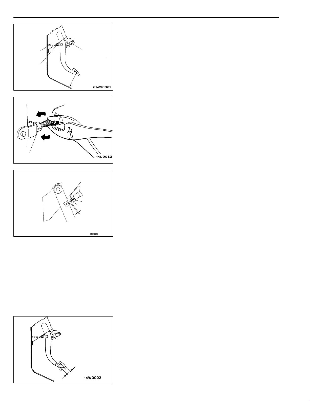
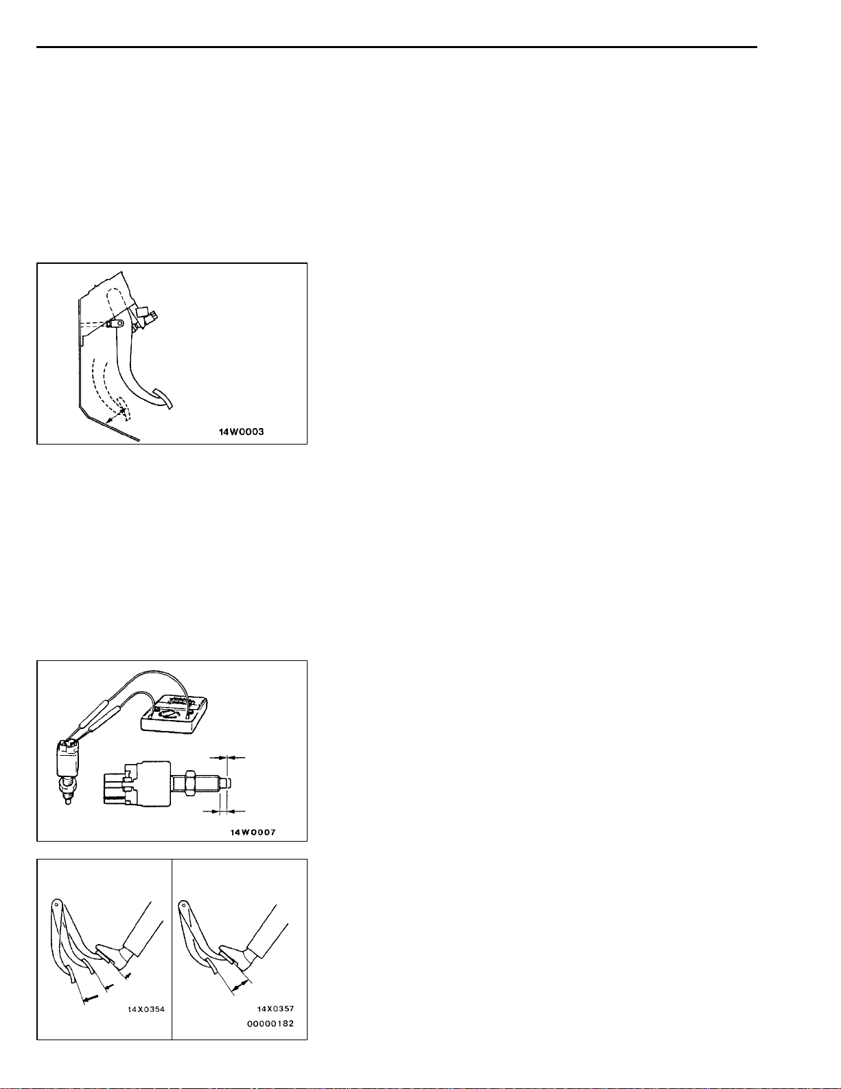
BRAKE PEDAL CHECK AND ADJUSTMENT
BRAKE PEDAL HEIGHT
1. Turn up the carpet, etc under the brake pedal.
2. Measure the brake pedal height as illustrated. If the brake
pedal height is not within the standard value, follow the
procedure below.
Standard value: 162.8 - 165.8 mm
(1) Disconnect the stop lamp switch connector.
(2) Adjust the brake pedal height by turning the operating
rod with pliers (with the operating rod lock nut
loosened), until the correct brake pedal height is
obtained.
(3) Secure by tightening the lock nut of the operating
rod.
(4) Push the stop lamp switch in the direction of the
pedal stroke until it stops. (The switch will slide if
it is pushed firmly.)
(5) Lift up the pedal until the operating rod is fully
extended, and then slide the stop lamp switch back
to the required position. Adjust the position of the
switch by turning it until the distance shown in the
illustration is correct.
(6) Connect the connector of the stop lamp switch.
(7) Check that the stop lamp is not illuminated with the
brake pedal unpressed.
3. Return the carpet etc.
BRAKE PEDAL FREE PLAY
With the engine stopped, depress the brake pedal two or
three times. After eliminating the vacuum in the power brake
booster, press the pedal down by hand, and confirm that
the amount of movement before resistance is met (the free
play) is within the standard value range.
BASIC BRAKE SYSTEM -
Standard value: 3–8 mm
If the free play exceeds the standard value, it is probably
due to excessive play between the retaining ring bolt and
brake pedal arm.
Check for excessive clearance and replace faulty parts as
required.
CLEARANCE BETWEEN BRAKE PEDAL AND FLOOR
BOARD
1. Turn back the carpet etc. under the brake pedal.
2. Start the engine, depress the brake pedal with
approximately 490 N of force, and measure the clearance
between the brake pedal and the floorboard.
Standard value: 90 mm or more
3. If the clearance is outside the standard value, check for
air trapped in the brake line, clearance between the lining
and the drum and dragging in the parking brake.
Adjust and replace defective parts as required.
On-vehicle Service
35A-7
No continuity
Good No good
Continuity
4mm
4. Return the carpet etc.
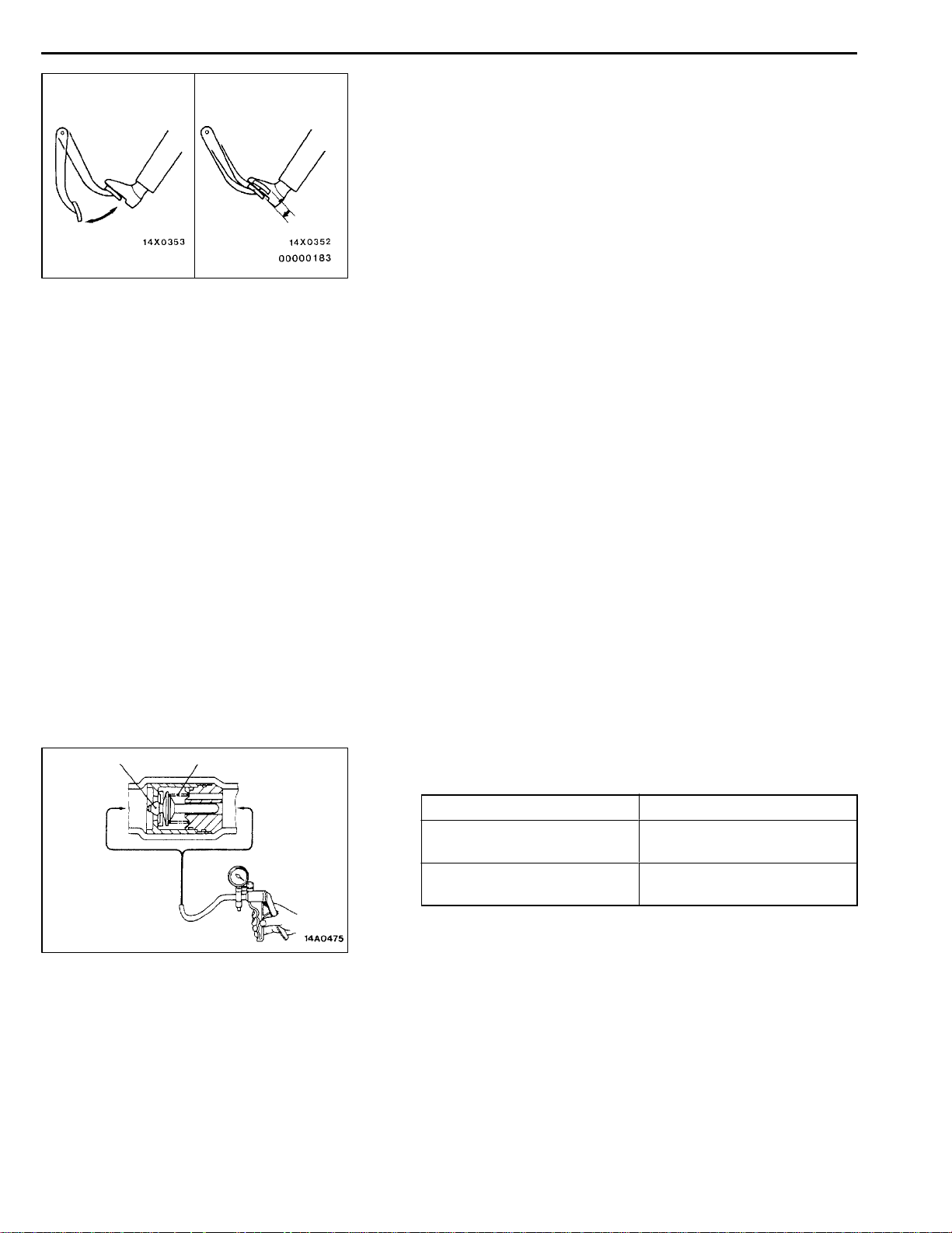
STOP LAMP SWITCH CHECK
35100890120
Connect a circuit tester to the stop lamp switch, and check
whether or not there is continuity when the plunger of the
stop lamp switch is pushed in and when it is released. The
stop lamp switch is in good condition if there is no continuity
when the plunger is pushed in to a depth of within 4 mm
from the outer case edge surface, and if there is continuity
when it is released.
BRAKE BOOSTER OPERATING TEST
35100100117
For simple checking of the brake booster operation, carry
out the following tests:
1. Run the engine for one or two minutes, and then stop
it.
If the pedal depresses fully the first time but gradually
becomes higher when depressed succeeding times, the
booster is operating properly, if the pedal height remains
unchanged, the booster is defective.
35A-8
BASIC BRAKE SYSTEM -
On-vehicle Service
When engine is
stopped
When engine is
started
2. With the engine stopped, step on the brake pedal several
times.
Then step on the brake pedal and start the engine.
If the pedal moves downward slightly, the booster is in
good condition. If there is no change, the booster is
defective.
3. With the engine running, step on the brake pedal and
then stop the engine.
Hold the pedal depressed for 30 seconds. If the pedal
height does not change, the booster is in good condition,
if the pedal rises, the booster is defective.
If the above three tests are okay, the booster performance
can be determined as good.
If one of the above three tests is not okay at last, the
check valve, vacuum hose, or booster will be defective.
Valve
Booster
side
Spring
AB
Intake
manifold
side
CHECK VALVE OPERATION CHECK
35100900151
1. Remove the vacuum hose. (Refer to P.35A-16.)
Caution
The check valve should not be removed from the
vacuum hose.
2. Check the operation of the check valve by using a vacuum
pump.
V acuum pump connection Accept/reject criteria
Connection at the brake
booster side (A)
Connection at the intake
manifold side (B)
A negative pressure (vacuum) is created and held.
A negative pressure (vacuum) is not created.
Caution
If the check valve is defective, replace it as an
assembly unit together with the vacuum hose.
BASIC BRAKE SYSTEM -
On-vehicle Service
35A-9
Output
pressure
Pressure gauge
Proportioning valve
Split point
Input pressure
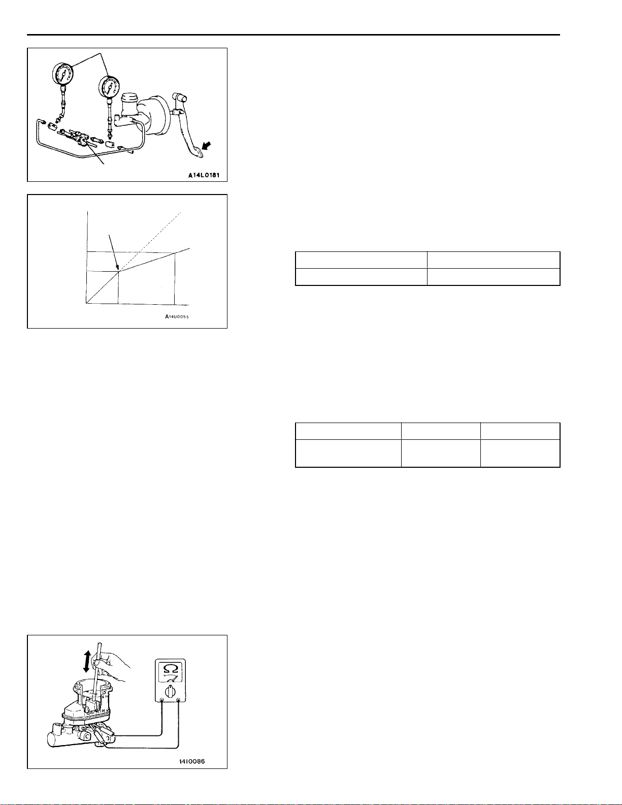
PROPORTIONING VALVE FUNCTION TEST
35100110172
1. Connect two pressure gauges, one each to the input
side and output side of the proportioning valve, as shown.
2. Bleed the air in the brake line and the pressure gauge.
3. While gradually depressing the brake pedal, make the
following measurements and check to be sure that the
measured values are within the allowable range.
(1) Output pressure begins to drop relative to input
pressure (split point).
Standard value:
MPa
Sedan Wagon
2.94±0.25 3.43±0.25
(2) Check to be sure that the output fluid pressure is
at the standard value when the pedal depression
force is increased so that the input fluid pressure
is at the values shown in the table below.
Standard value:
MPa
Sedan Wagon
Output fluid pressure
(Input fluid pressure)
4.66±0.39
(9.81)
5.80±0.39
(9.81)
(3) Output pressure difference between left and right
brake lines.
Limit: 0.39 MPa
4. If the measured pressures are not within the permissible
ranges, replace the proportioning valve.
BRAKE FLUID LEVEL SENSOR CHECK
35100910123
The brake fluid level sensor is in good condition if there is
no continuity when the float surface is above “MIN” and if
there is continuity when the float surface is below “MIN”.
35A-10
BASIC BRAKE SYSTEM -
On-vehicle Service
BLEEDING
35100140089
Caution
Use the specified brake fluid. Avoid using a mixture of
the specified brake fluid and other fluid.
Specified brake fluid: DOT3 or DOT4
MASTER CYLINDER BLEEDING
The master cylinder used has no check valve, so if bleeding
is carried out by the following procedure, bleeding of air from
the brake pipeline will become easier. (When brake fluid is
not contained in the master cylinder.)
(1) Fill the reserve tank with brake fluid.
(2) Keep the brake pedal depressed.
(3) Have another person cover the master cylinder outlet
with a finger.
(4) With the outlet still closed, release the brake pedal.
(5) Repeat steps (2)- (4) three or four times to fill the inside
of the master cylinder with brake fluid.
4 (2)
2 (4)
( ): R.H. drive vehicles
When new When worn
Pad
Wear indicator
Brake disc
1 (3)
3 (1)
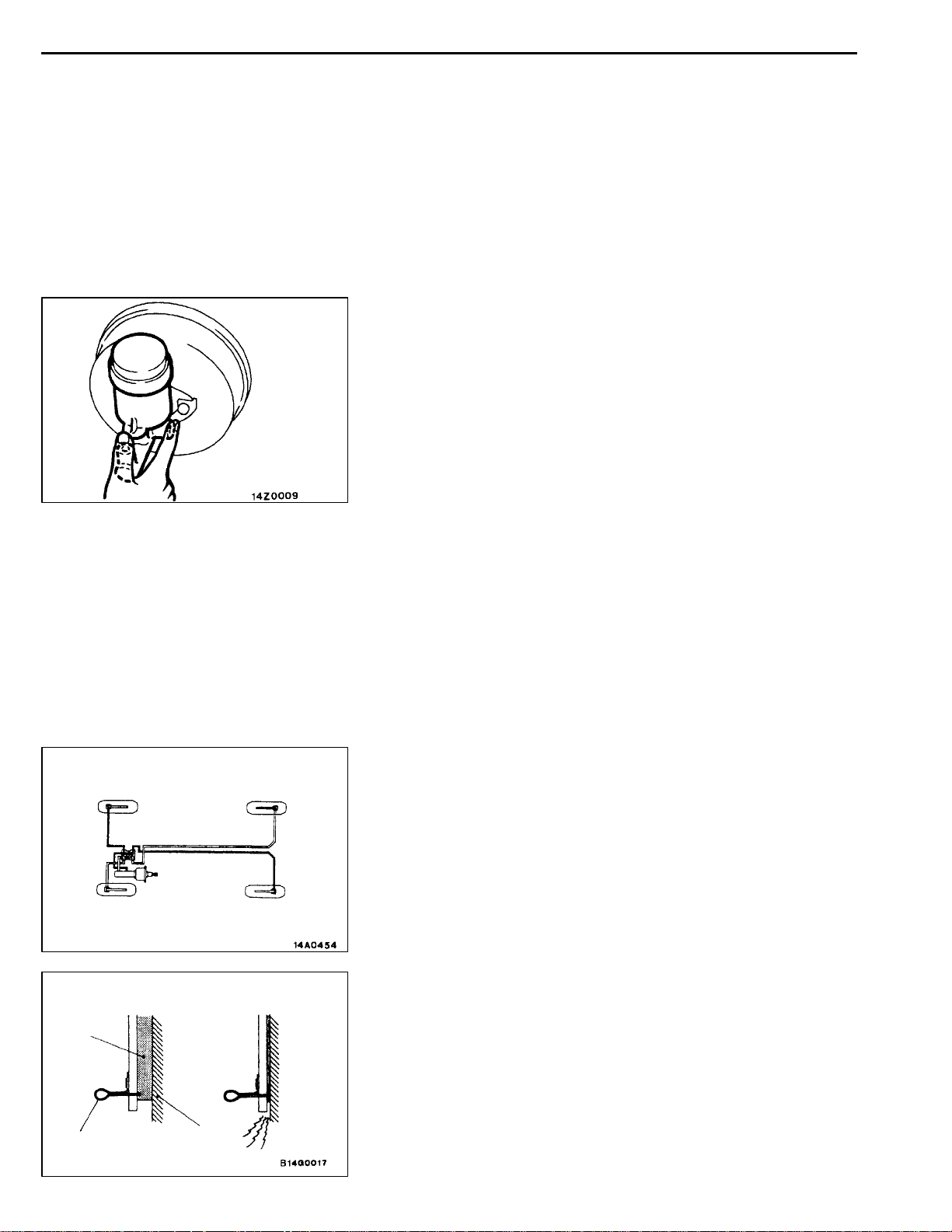
BRAKE PIPE LINE BLEEDING
Bleed the air in the sequence shown in the figure.
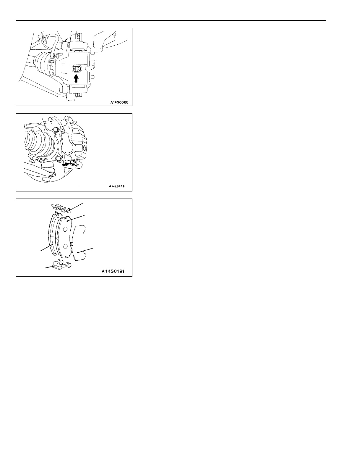
DISC BRAKE PAD CHECK AND
REPLACEMENT
NOTE
The left side outer brake pad has a wear indicator.
The wear indicator contacts the brake disc when the brake
pad thickness becomes 2 mm and emit a squealing sound
to warn the driver.
35100230014
BASIC BRAKE SYSTEM -
1. Check brake pad thickness through caliper body check
port.
Standard value: 10 mm
Limit: 2.0 mm
Caution
1. When the limit is exceeded, replace the pads at
both sides, and also the brake pads for the wheels
on the opposite side at the same time.
2. If there is a significant difference in the thickness
of the pads on the left and right sides, check the
sliding condition of the piston and guide pin.
2. Remove the guide pin. Lift caliper assembly and retain
with wires.
Caution
Do not wipe off the special grease that is on the guide
pin or allow it to contaminate the guide pin.
On-vehicle Service
35A-11
3
2
1
3
4
3. Remove the following parts from caliper support.
(1) Pad and wear indicator assembly <L.H.>, and pad
assembly <R.H.>
(2) Pad assembly
(3) Pad liner
(4) Outer shim
4. In order to measure the brake drag force after pad
installation, measure the rotary-sliding resistance of the
hub with the pads removed. (Refer to P.35A-19.)
5. Install the pads and the caliper assembly, and then check
the brake drag force. (Refer to P.35A-19.)
35A-12
BASIC BRAKE SYSTEM -
On-vehicle Service
DISC BRAKE ROTOR CHECK
35100290012
Caution
When servicing disc brakes, it is necessary to exercise caution to keep the disc brakes within
the allowable service values in order to maintain normal brake operation.
Before re-finishing or re-processing the brake disc surface, the following conditions should be checked.
Inspection items Remarks
D
Scratches, rust, saturated lining materials
and wear
Run-out or drift Excessive run-out or drift of the discs will increase the pedal depression
Change in thickness (parallelism) If the thickness of the disc changes, this will cause pedal pulsation,
Inset or warping (flatness) Overheating and improper handling while servicing will cause inset or
If the vehicle is not driven for a certain period, the sections of
the discs that are not in contact with lining will become rusty, causing
noise and shuddering.
D
If grooves resulting from excessive disc wear and scratches are
not removed prior to installing a new pad assembly, there will
momentarily be inappropriate contact between the disc and the
lining (pad).
resistance due to piston knock-back.
shuddering and surging.
warping.
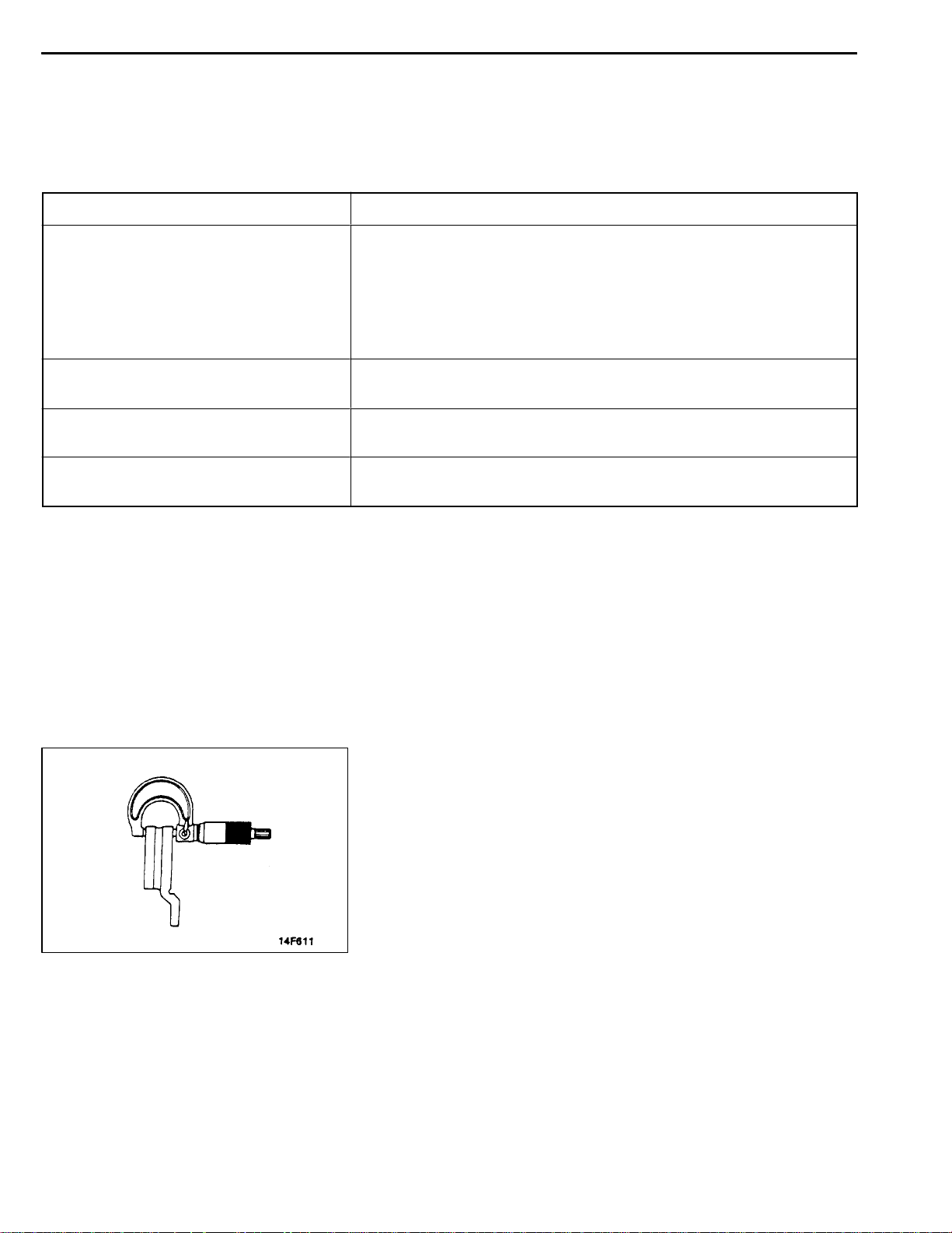
THICKNESS CHECK
35100240017
1. Using a micrometer, measure disc thickness at eight
positions, approximately 45_apart and 10 mm in from
the outer edge of the disc.
Brake disc thickness
Standardvalue: 24.0 mm <Front>, 10.0 mm<Rear>
Limit: 22.4 mm <Front>, 8.4 mm <Rear>
Thickness variation (at least 8 positions)
The difference between any thickness measurements
should not be more than 0.015 mm.
2. If the disc is beyond the limits for thickness, remove it
and install a new one. If thickness variation exceeds the
specification, replace the brake disc or turn rotor with
on the car type brake lathe (“MAD, DL-8700PF” or
equivalent).
BASIC BRAKE SYSTEM -
On-vehicle Service
35A-13
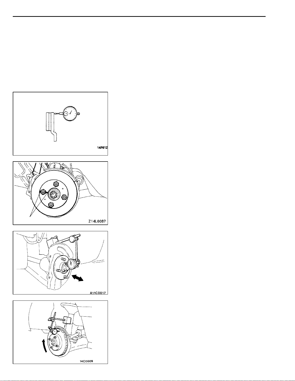
RUN-OUT CHECK
35100250010
1. Remove the caliper support; then raise the caliper
assembly upward and secure by using wire.
2. Inspect the disc surface for grooves, cracks and rust.
Clean the disc thoroughly and remove all rust.
3. Place a dial gauge approximately 5 mm from the outer
circumference of the brake disc, and measure the run-out
of the disc.
Limit:
0.06 mm or less <Front>
0.08 mm or less <Rear>
NOTE
Tighten the nuts in order to secure the disc to the hub.
RUN-OUT CORRECTION
35100180081
1. If the run-out of the brake disc is equivalent to or exceeds
the limit specification, change the phase of the disc and
hub, and then measure the run-out again.
(1) Before removing the brake disc, chalk both sides
of the wheel stud on the side at which run-out is
greatest.
Chalk mark
(2) Remove the brake disc, and then place a dial gauge
as shown in the illustration; then move the hub in
the axial direction and measure the play.
Limit: 0.05 mm
If the play is equivalent to or exceeds the limit,
disassemble the hub knuckle and check each part.
(3) If the play does not exceed th e limit specification,
install the brake disc at a position 180_ away from
the chalk mark, and then check the run-out of the
brake disc once again.
2. If the run-out cannot be corrected by changing the phase
of the brake disc, replace the disc or turn rotor with on
the car type brake lathe (“MAD, DL-8700PF” or
equivalent).
35A-14
BASIC BRAKE SYSTEM -
On-vehicle Service
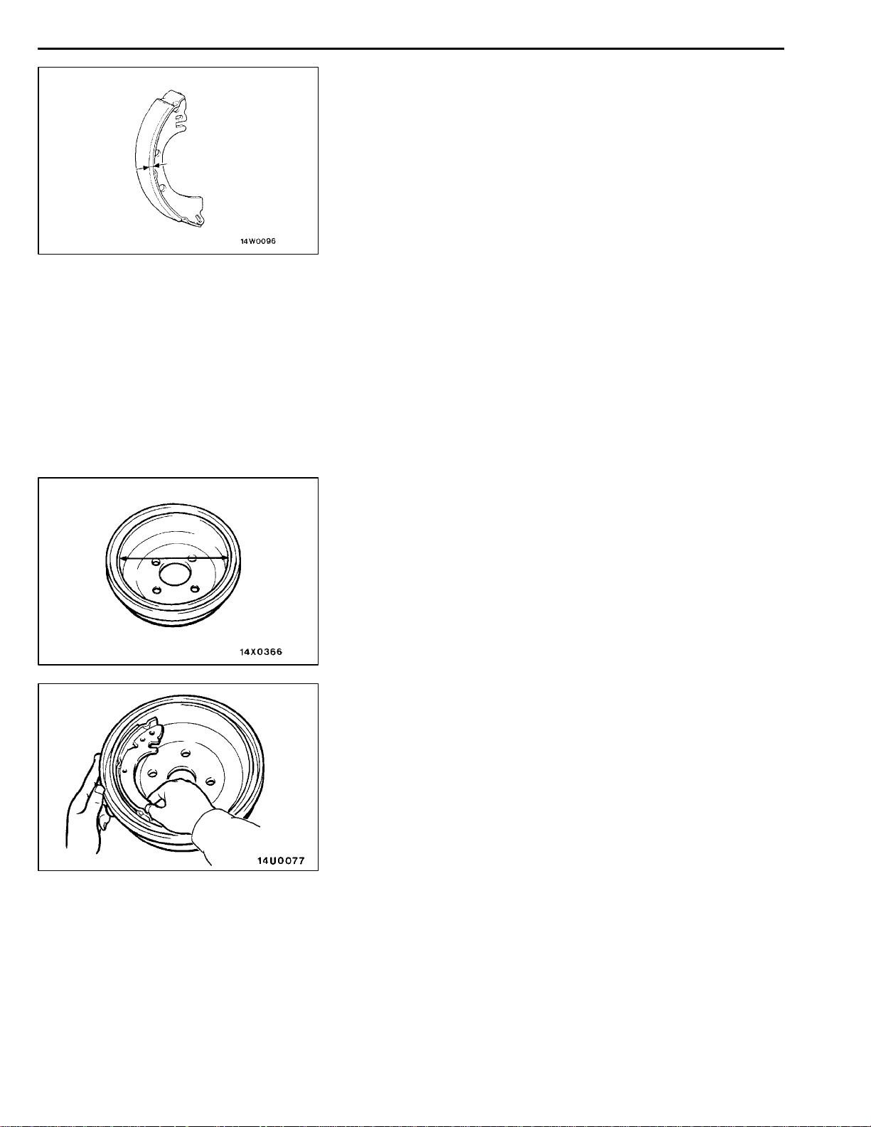
BRAKE LINING THICKNESS CHECK
1. Remove the brake drum.
2. Measure the wear of the brake lining at the place worn
the most.
Standard value: 4.4 mm
Limit: 1.0 mm
Replace the shoe and lining assembly if brake lining
thickness is less than the limit or if it is not worn evenly.
For information concerning the procedures for installation
of the shoe and lining assembly, refer to P.35A-24.
Caution
1. Whenever the shoe and lining assembly is
replaced, replace both R.H. and L.H. assemblies
as a set to prevent car from pulling to one side
when braking.
2. If there is a significant difference in the thickness
of the shoe and lining assemblies on the left and
right sides, check the sliding condition of the
piston.
35100300166
BRAKE DRUM INSIDE DIAMETER CHECK
35100320148
1. Remove the brake drum.
2. Measure the inside diameter of t he brake drum at two
or more locations.
Standard value: 203 mm
Limit: 205 mm
3. Replace brake drums, shoe and lining assembly when
wear exceeds the limit value or is badly imbalanced.
BRAKE LINING AND BRAKE DRUM
CONNECTION CHECK
1. Remove the brake drum.
2. Remove the shoe and lining assembly.
(Refer to P.35A-24.)
3. Chalk inner surface of brake drum and rub with shoe
and lining assembly.
4. Replace shoe and lining assembly or brake drums if there
are any irregular contact area.
NOTE
Clean off chalk after check.
35100310169
BASIC BRAKE SYSTEM -
Brake Pedal
35A-15
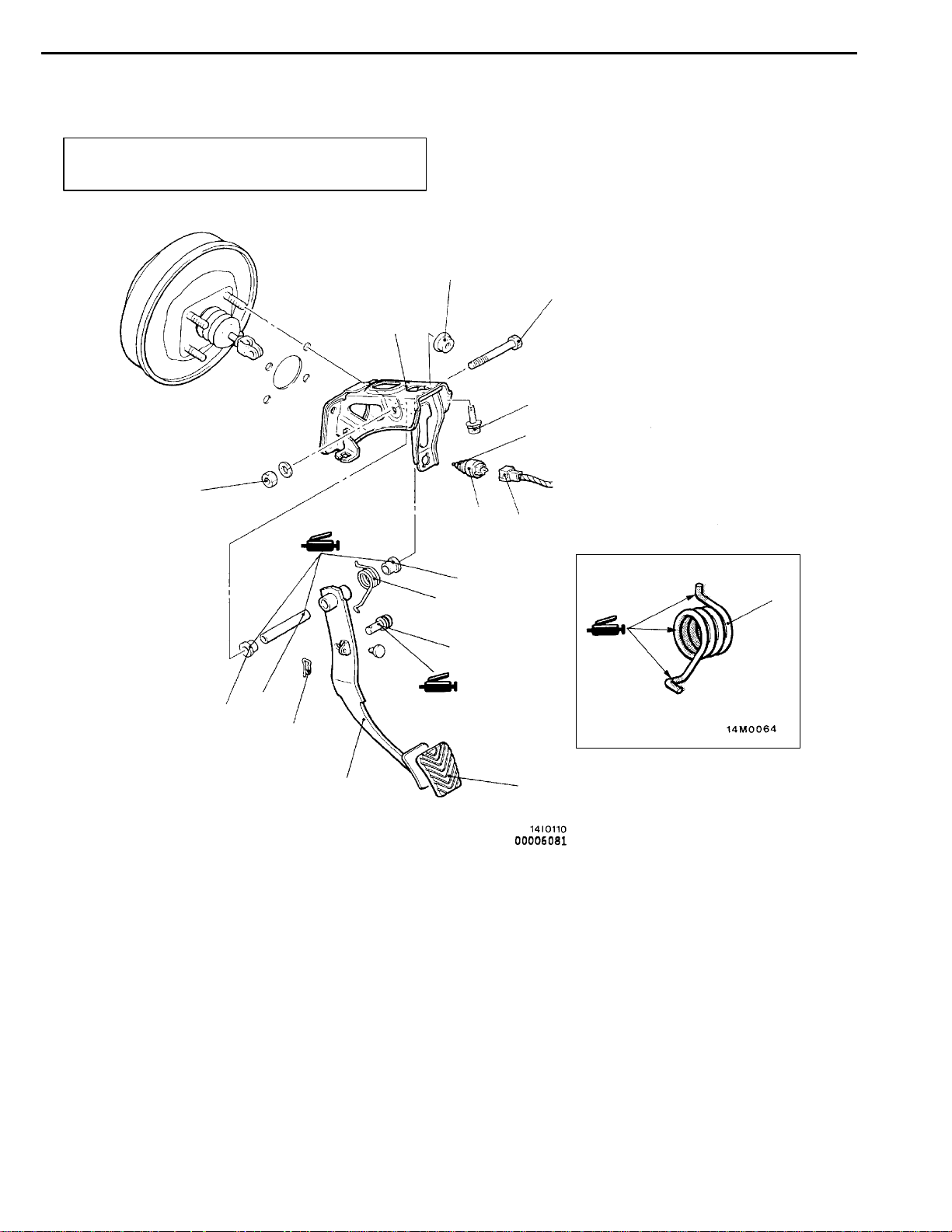
BRAKE PEDAL
REMOVAL AND INSTALLATION
Post-installation Operation
Brake Pedal Adjustment (Refer to P.35A-6.)
29 Nm
11
14 Nm
35100340243
5
12 Nm
13 Nm
2
1
10
9
3
6
Removal steps
1. Stop lamp switch connector
2. Stop lamp switch
3. Snap pin
4. Pin assembly
5. Brake pedal shaft bolt
6. Brake pedal
9
8
8
4
7
7. Brake pedal pad
8. Brake pedal return spring
9. Bushing
10. Pipe
11. Pedal support member
35A-16
BASIC BRAKE SYSTEM -
Master Cylinder and Brake Booster
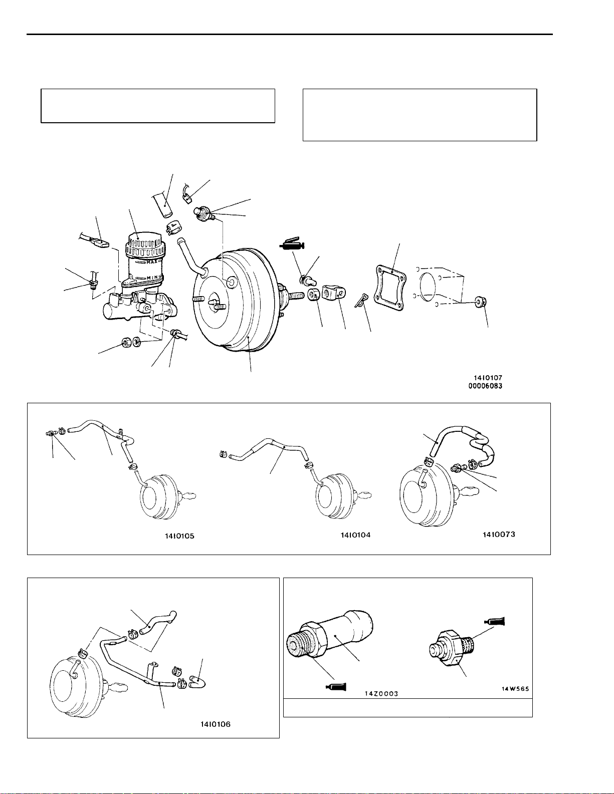
MASTER CYLINDER AND BRAKE BOOSTER
REMOVAL AND INSTALLATION
Pre-removal Operation
Brake Fluid Draining
2
15 Nm
1
6
3
11
12
20 - 25 Nm
Post-installation Operation
D Brake Fluid Supplying
D Brake Line Bleeding (Refer to P.35A-10.)
D Brake Pedal Adjustment (Refer to P.35A-6.)
9
22 Nm
10
8
35100370242
14
14 Nm
10 Nm
15 Nm
1
<L.H. drive vehicles - 4G6,6A1>
7
15 Nm
<R.H. drive vehicles - 4D6>
6
4
13
<L.H. drive vehicles - 4D6>
4
<R.H. drive vehicles - 4G6,6A1>
6
7
15 Nm
4
7
12
5
Sealant: 3M ATD Part No.8661 or equivalent
BASIC BRAKE SYSTEM -
Removal steps
1. Brake pipe connection
2. Brake fluid level sensor connector
3. Master cylinder assembly
"BADPush rod protruding length check and
adjustment
4. Vacuum hose <4D6>
5. Vacuum pipe <4D6>
"AA 6. Vacuum hose
(with built-in check valve)
INSTALLATION SERVICE POINTS
"AA
Insert securely and completely until the vacuum hose at the
engine side contacts the edge of the hexagonal part of the
fitting, and then secure by using the hose clip.
Master Cylinder and Brake Booster
7. Fitting
8. Snap pin
9. Pin assembly
10. Clevis
11. Vacuum switch connector <4D6>
12. Vacuum switch <4D6>
13. Brake booster
14. Sealer
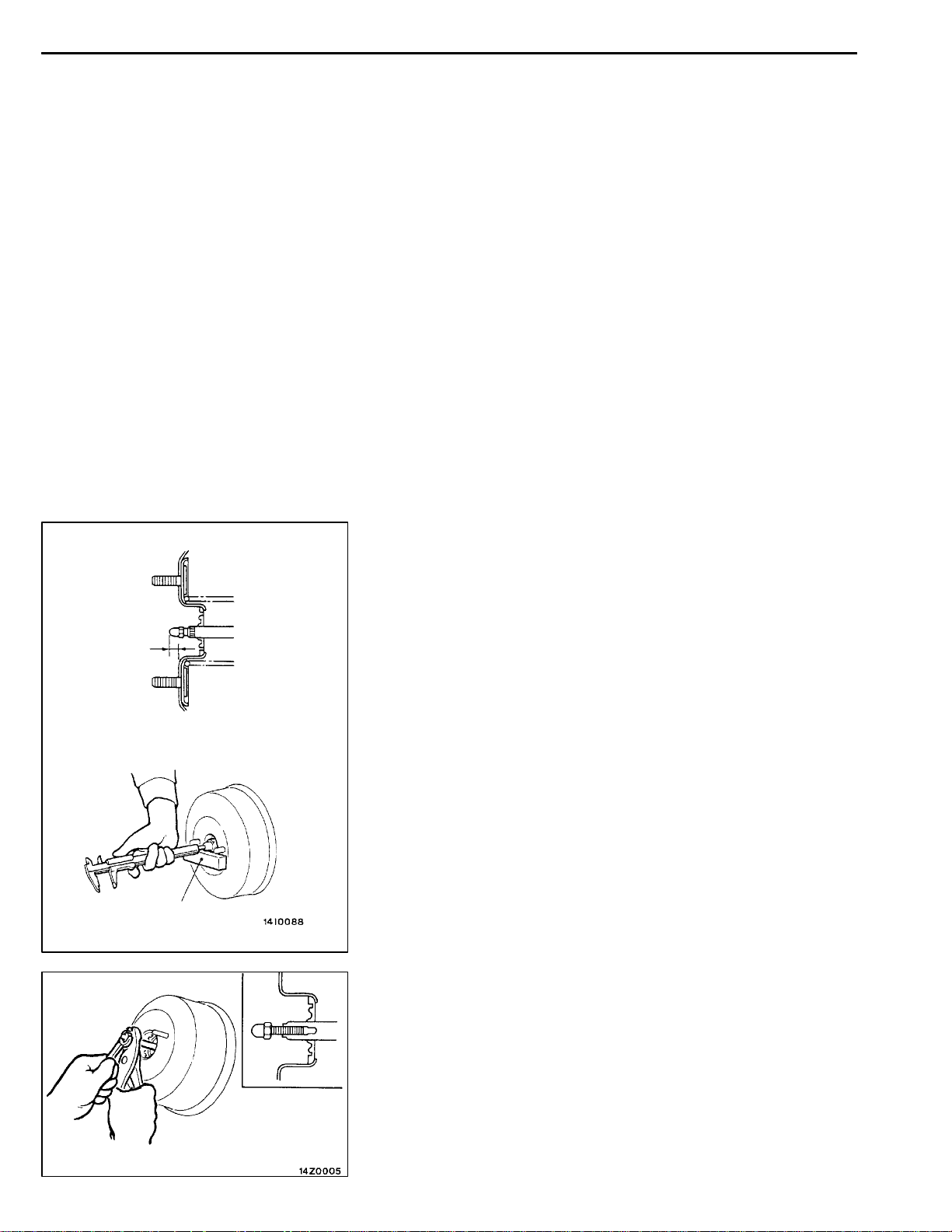
VACUUM HOSE CONNECTION
35A-17
A
Measuring dimension A
Block gauge
"BA
PUSH ROD PROTRUDING LENGTH CHECK AND
ADJUSTMENT
1. Measure dimension A.
Standard value: 9.65 - 9.90 mm
2. If the protruding length is not within the standard value
range, adjust by changing the push rod length by turning
the end of the push rod.
35A-18
BASIC BRAKE SYSTEM -
Master Cylinder and Brake Booster
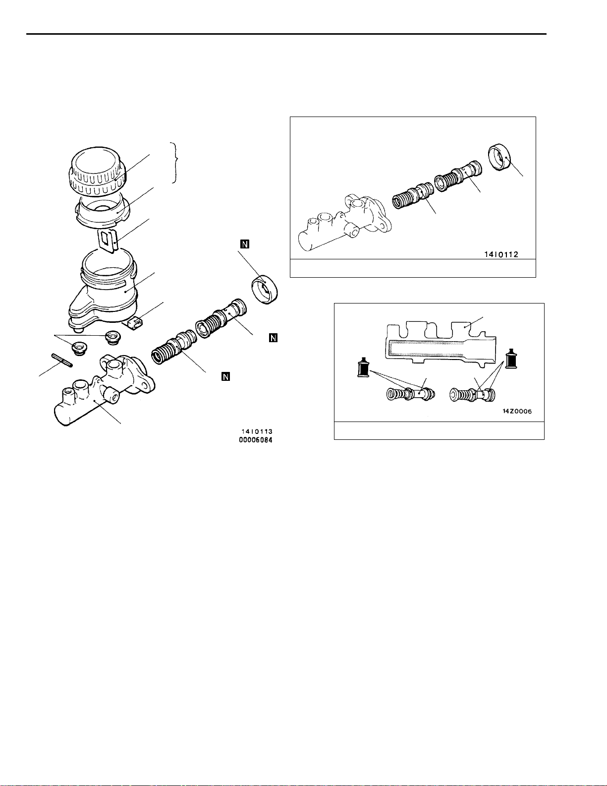
MASTER CYLINDER
DISASSEMBLY AND REASSEMBLY
2
5
8
1
3
9
7
4
35100420145
9
10
11
Master cylinder kit
12
10
6
12
Disassembly steps
1. Reservoir cap assembly
2. Reservoir cap
3. Diaphragm
4. Brake fluid level indicator assembly
5. Float
6. Spring pin
11
Brake fluid: DOT3 or DOT4
7. Reservoir tank
8. Reservoir seal
9. Piston retainer
10. Primary piston assembly
11. Secondary piston assembly
12. Master cylinder body
11
10
Loading...