


 Loading...
EN
9
DLP™ PROJECTOR
MODEL
XD600U/XD600U-G WD620U/WD620U-G
User Manual
XD600U
XD600U-G WD620U WD620U-G
This User Manual is important to you.
Please read it before using your projector.
ENGLISH
CAUTION
RISK OF ELECTRIC SHOCK
DO NOT OPEN
CAUTION : TO REDUCE THE RISK OF ELECTRIC
SHOCK,
DO NOT REMOVE COVER (OR BACK)
NO USER-SERVICEABLE PARTS INSIDE
REFER SERVICING TO QUALIFIED
SERVICE PERSONNEL.
The lightning flash with arrowhead symbol within an equilateral triangle is intended to alert the user to the presence of uninsulated "dangerous voltage" within the product’s enclosure that may be of sufficient magnitude to constitute a risk of electric shock.
The exclamation point within an equilateral triangle is intended to alert the user to the presence of important operating and maintenance (servicing) instructions in the literature accompanying the appliance.
WARNING:
TO PREVENT FIRE OR SHOCK HAZARD, DO NOT EXPOSE THIS APPLIANCE TO RAIN OR MOISTURE.
CAUTION:
TO PREVENT ELECTRIC SHOCK, DO NOT USE THIS (POLARIZED) PLUG WITH AN EXTENSION CORD, RECEPTACLE OR OTHER OUTLET UNLESS THE BLADES CAN BE FULLY INSERTED TO PREVENT BLADE EXPOSURE.
NOTE:
SINCE THIS PROJECTOR IS PLUGGABLE EQUIPMENT, THE SOCKET-OUTLET SHALL BE INSTALLED NEAR THE EQUIPMENT AND SHALL BE EASILY ACCESSIBLE.
WARNING
Use the attached specified power supply cord. If you use another power supply cord, it may cause interference with radio and television reception.
Use the attached RGB cable and the shielded LAN cable with this equipment so as to keep interference within the limits of an FCC Class B device.
This apparatus must be grounded.
DO NOT LOOK DIRECTLY INTO THE LENS WHEN THE PROJECTOR IS IN THE POWER ON MODE.
When using the projector in Europe: COMPLIANCE NOTICE
This Projector complies with the requirements of the EC Directive 2004/108/EC "EMC Directive" and 2006/95/EC "Low Voltage Directive".
The electro-magnetic susceptibility has been chosen at a level that gains proper operation in residential areas, on business and light industrial premises and on small-scale enterprises, inside as well as outside of the buildings. All places of operation are characterized by their connection to the public low voltage power supply system.
CAUTION
Not for use in a computer room as defined in the Standard for the Protection of Electronic Computer/Data Processing Equipment, ANSI/NFPA 75.
The attached power cord is to be used exclusively for this product. Never use it for other products.
WARNING
Use the attached RGB cable and the shielded LAN cable with this equipment so as to keep interference within the limits of an EN55022 Class B device.
Please follow WARNING instructions.
Note: This symbol mark is for EU countries only.
This symbol mark is according to the directive 2002/96/EC Article 10 Information for users and Annex IV, and/or to the directive 2006/66/EC Article 20 Information for end-users and Annex II.
Your MITSUBISHI ELECTRIC product is designed and manufactured with high quality materials and components which can be recycled and/or reused.
This symbol means that electrical and electronic equipment, batteries and accumulators, at their end-of-life, should be disposed of separately from your household waste. If a chemical symbol is printed beneath the symbol shown above, this chemical symbol means that the battery or accumulator contains a heavy metal at a certain concentration. This will be indicated as follows:
Hg: mercury (0,0005%), Cd: cadmium (0,002%), Pb: lead (0,004%)
In the European Union there are separate collection systems for used electrical and electronic products, batteries and accumulators.
Please, dispose of this equipment, batteries and accumulators correctly at your local community waste collection/recycling centre.
Please, help us to conserve the environment we live in!
EN-2
Contents
Important safeguards |
................................................................................................................................4 |
Overview................................................................................................................................................... |
6 |
Remote control ......................................................................................................................................... |
8 |
Installation ................................................................................................................................................ |
9 |
Basic connections................................................................................................................................... |
12 |
Preparation ............................................................................................................................................. |
15 |
Basic operation....................................................................................................................................... |
16 |
Menu operation....................................................................................................................................... |
19 |
Image adjustment ................................................................................................................................... |
27 |
Network settings ..................................................................................................................................... |
29 |
Advanced features.................................................................................................................................. |
32 |
Lamp replacement.................................................................................................................................. |
35 |
Troubleshooting ...................................................................................................................................... |
37 |
Indicators ................................................................................................................................................ |
40 |
Specifications ......................................................................................................................................... |
41 |
ENGLISH
Declaration of Conformity
Model Number : |
XD600U/XD600U-G/WD620U/WD620U-G |
Trade Name : |
MITSUBISHI ELECTRIC |
Responsible party : |
Mitsubishi Digital Electronics America, Inc. |
|
9351 Jeronimo Road, Irvine, CA 92618 U.S.A |
Telephone number : |
+1-(949) 465-6000 |
This device complies with Part 15 of the FCC Rules. Operation is subject to the following two conditions:
(1)this device may not cause harmful interference, and
(2)this device must accept any interference received, including interference that may cause undesired operation.
Trademark, Registered trademark
Macintosh is registered trademark of Apple Computer Inc.
DLPTM, Digital Micromirror Device, DMD, and BrilliantColorTM are all trademarks of Texas Instruments.
HDMI, the HDMI logo and High-Definition Multimedia Interface are trademarks or registered trademarks of HDMI Licensing LLC.
Microsoft, Windows, Windows 2000, Windows XP, Windows Vista, and Internet Explorer are registered trademarks, trademarks, or trade names of Microsoft Corporation in the U.S. and/or other countries.
Other brand or product names are trademarks or registered trademarks of their respective holders.
EN-3

Important safeguards
Please read all these instructions regarding your projector and retain them for future reference. Follow all warnings and instructions marked on the projector.
1.Read instructions
All the safety and operating instructions should be read before the appliance is operated.
2.Retain instructions
The safety and operating instructions should be retained for future reference.
3.Warnings
All warnings on the appliance and in the operating instructions should be adhered to.
4.Instructions
All operating instructions must be followed.
5.Cleaning
Unplug this projector from the wall outlet before cleaning it. Do not use liquid aerosol cleaners. Use a damp soft cloth for cleaning.
6.Attachments and equipment
Never add any attachments and/or equipment without the approval of the manufacturer as such additions may result in the risk of fire, electric shock or other personal injury.
7.Water and moisture
Do not use this projector near water or in contact with water.
8.Accessories
Do not place this projector on an unstable cart, stand, tripod, bracket or table. Use only with a cart, stand, tripod bracket, or table recommended by the manufacturer or sold with the projector. Any mounting of the appliance should follow the manufacturer’s instructions and should use a mounting accessory recommended by the manufacturer.
An appliance and cart combination should be moved with care. Quick stops, excessive force and uneven surfaces may cause the appliance and cart combination to overturn.
9.Ventilation
Slots and openings in the cabinet are provided for ventilation, ensuring reliable operation of the projector and to protect it from overheating. Do not block these openings or allow them to be blocked by placing the projector on a bed, sofa, rug, or bookcase. Ensure that there is adequate ventilation and that the manufacturer’s instructions have been adhered to.
10.Power sources
This projector should be operated only from the type of power source indicated on the marking label. If you are not sure of the type of power, please consult your appliance dealer or local power company.
11.Power-cord protection
Power-supply cords should be routed so that they are not likely to be walked on or pinched by items placed upon or against them. Pay particular attention to cords at plugs, convenience receptacles, and points where they exit from the appliance. Do not put the power cord under a carpet.
12.Overloading
Do not overload wall outlets and extension cords as this can result in a fire or electric shock.
13.Objects and liquids
Never push objects of any kind through openings of this projector as they may touch dangerous voltage points or short-out parts that could result in a fire or electric shock. Never spill liquid of any kind on the projector.
14.Servicing
Do not attempt to service this projector yourself. Refer all servicing to qualified service personnel.
15.Damage requiring service
Unplug this projector from the wall outlet and refer servicing to qualified service personnel under the following conditions:
(a)If the power-supply cord or plug is damaged.
(b)If liquid has been spilled, or objects have fallen into the projector.
(c)If the projector does not operate normally after you follow the operating instructions. Adjust only those controls that are covered by the operating instructions. An improper adjustment of other controls may result in damage and may often require extensive work by a qualified technician to restore the projector to its normal operation.
(d)If the projector has been exposed to rain or water.
(e)If the projector has been dropped or the cabinet has been damaged.
(f)If the projector exhibits a distinct change in performance - this indicates a need for service.
16.Replacement parts
When replacement parts are required, be sure that the service technician has used replacement parts specified by the manufacturer or parts having the same characteristics as the original part. Unauthorized substitutions may result in fire, electric shock or other hazards.
17.Safety check
Upon completion of any service or repair to this projector, ask the service technician to perform safety checks determining that the projector is in a safe operating condition.
EN-4

WARNING:
Unplug immediately if there is something wrong with your projector.
Do not operate if smoke, strange noise or odor comes out of your projector. It may cause fire or electric shock. In this case, unplug immediately and contact your dealer.
Never remove the cabinet.
This projector contains high voltage circuitry. An inadvertent contact may result in an electric shock. Except as specifically explained in User Manual, do not attempt to service this product by yourself. Please contact your dealer when you want to fix, adjust, or inspect the projector.
Do not modify the projector.
It can lead to fire or electric shock.
Do not keep using the damaged projector.
If the projector is dropped and the cabinet is damaged, unplug the projector and contact your dealer for inspection. It may lead to fire if you keep using the damaged projector.
Do not face the projection lens to the sun.
It can lead to fire.
Use correct voltage.
If you use incorrect voltage, it can lead to fire.
Do not place the projector on uneven surface.
Place the projector on a level and stable surface only.
Do not look into the lens when the projector is operating.
It may hurt your eyes. Never let children look into the lens when the projector is on.
Do not unplug the power cord during operation.
It can lead to lamp breakage, fire, electric shock or other trouble. Wait for the fan to stop before unplugging the power cord.
Do not touch the air outlet grilles and bottom plate.
Do not touch them or put other equipment close to the air outlet grilles because they become hot during operation. The heated air outlet grilles and bottom plate may cause injury or damage to other equipment. Also, do not put the projector on a desk that is easily affected by heat.
Do not look into the air outlet grilles when projector is operating.
Heat, dust, etc. may blow out of them and hurt your eyes.
Do not block the air inlet and outlet grilles.
If they are blocked, heat may be generated inside the projector, causing deterioration in the projector quality and fire.
Do not use flammable solvents (benzene, thinner, etc.) and flammable aerosols near the projector.
Flammable substances may ignite causing fire or breakdown because the temperature inside the projector rises very high while the lamp is illuminating.
Do not use the projector with condensation on it.
It can lead to breakdown or other failure.
Place of installation
For safety’s sake, do not use the projector at any place subjected to high temperature and high humidity. Please maintain an operating temperature, humidity, and altitude as specified below.
•Operating temperature: between +41°F (+5°C) and +95°F (+35°C)
•Operating humidity: between 30% and 90%
•Never put any heat-producing device under the projector to prevent the projector from being overheated.
•Do not install the projector at a place that is unstable or subject to vibration.
•Do not install the projector near any equipment that produces a strong magnetic field. Also refrain from installing the projector near any cable carrying a large amount of current.
•Place the projector on a solid, vibration-free surface. Otherwise it may fall, causing serious injury or damage.
•Do not stand the projector on its end. It may fall, causing serious injury or damage.
•Slanting the projector more than ±10° (right and left) or ±15° (front and rear) may cause trouble or explosion of the lamp.
•Do not place the projector near air-conditioning unit, heater, or humidifier to avoid hot or moist air to the exhaust and ventilation hole of the projector.
•Be sure to use this projector at an altitude of less than 1500 meters.
When removing the lamp from the ceiling-mounted projector
Be sure to use the lamp replacement attachment designed specifically for this projector when replacing the lamp with a new one. Lamp fragments may fall from the inside if the lamp were broken.
COMPLIANCE NOTICE OF FCC
This equipment has been tested and found to comply with the limits for a Class B digital device, pursuant to Part 15 of the FCC Rules. These limits are designed to provide reasonable protection against harmful interference in a residential installation. This equipment generates, uses and can radiate radio frequency energy and, if not installed and used in accordance with the instructions, may cause harmful interference to radio communications. However, there is no guarantee that interference will not occur in a particular installation. If this equipment does cause harmful interference to radio or television reception, which can be determined by turning the equipment off and on, the user is encouraged to try to correct the interference by one or more of the following measures:
•Reorient or relocate the receiving antenna.
•Increase the separation between the equipment and receiver.
•Connect the equipment into an outlet on a circuit different from that to which the receiver is connected.
•Consult the dealer or an experienced Radio / TV technician for help.
Changes or modifications not expressly approved by Mitsubishi could void the user’s authority to operate this equipment.
COMPLIANCE NOTICE OF INDUSTRY CANADA
This Class B digital apparatus complies with Canadian ICES-003.
ENGLISH
EN-5
Overview
11 |
3 1 2 |
4 |
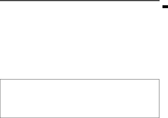
1 |
FOCUS ring |
|
|
|
2 |
ZOOM ring |
|
|
|
3 |
Control panel |
|
|
|
4 |
Air inlet grille |
|
|
|
5 |
Remote control sensor (Front) |
|
|
|
6 |
Air outlet grille |
|
|
|
7 |
Terminal board |
|
|
|
8 |
Speaker |
|
|
|
9 |
Adjustment feet |
|
|
|
10 |
Lock bar |
|
|
|
11 |
Lamp cover |
|
|
Caution: |
|
|
Do not replace the lamp immediately after using the pro- |
9 |
5 8 10 |
jector because the lamp would be extremely hot and it |
may cause burns. |
6
7
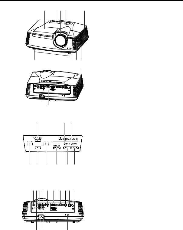
Control panel
6 |
4 |
2 |
7 |
8 |
9 |
5 |
3 |
1 |
1Power button
2POWER indicator
3MENU button
4STATUS indicator
5KEYSTONE/ENTER button
6AUTO POSITION / S button
7COMPUTER / W button
8T button
9VIDEO/ X button
Important:
•While the menu or the screen for the keystone adjustment or password entry is being displayed, the COM-
PUTER, VIDEO, and AUTO POSITION buttons function as the W, X, and S buttons respectively.
•While the menu is on the screen, the KEYSTONE button functions as the ENTER button.
Terminal board
7 5 13 8 14 2 |
3 10 12 4 |
1 |
Power jack |
|
|
2 |
COMPUTER IN terminal (1, 2) (Mini D-SUB 15-pin) |
|
|
3 |
MONITOR OUT terminal (Mini D-SUB 15-pin) |
|
|
4 |
Remote control sensor (Rear) |
|
|
5 |
AUDIO IN-1 terminal (Mini jack) |
|
|
6 |
AUDIO IN-2 terminal (Mini jack) |
|
|
7 |
AUDIO OUT terminal (Mini jack) |
|
|
8 |
S-VIDEO terminal |
|
|
9 |
VIDEO terminal |
|
|
10 |
SERIAL (RS-232C) terminal (Mini DIN) |
|
|
11 |
Kensington Lock |
|
|
12 |
LAN terminal (RJ-45) |
6 1 9 |
11 |
13 |
AUDIO IN-3 terminals (L/R) |
|
|
14 |
HDMI terminal (HDMI 19-pin) |
Kensington Lock
This projector has a Kensington Security Standard connector for use with Kensington MicroSaver Security System.
Refer to the information that came with the Kensington System for instructions on how to use it to secure the projector. Please contact Kensington Technology Group below.
Kensington Technology Group 2855 Campus Drive
San Mateo, CA 94403, U.S.A.
Phone: +1- (650)572-2700 Fax: +1- (650)572-9675
EN-6
Overview (continued)
Bottom side
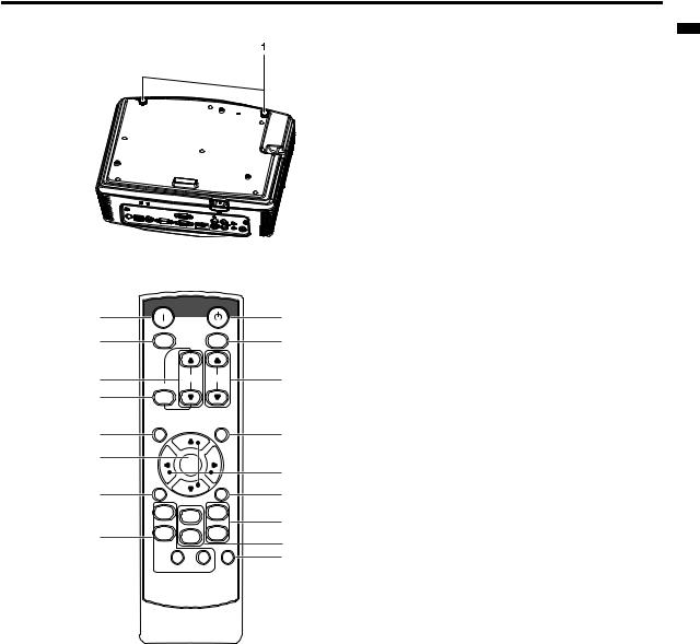
Remote control
|
ON |
|
STANDBY |
1 |
|
|
|
|
MAGNIFY |
|
ASPECT |
2 |
|
|
|
3 |
|
|
UP |
|
VOL |
PAGE |
|
|
|
||
4 |
KEYSTONE |
|
DOWN |
|
|
|
|
|
|
|
AUTO |
5 |
MENU |
|
POSITION |
|
|
|
|
6 |
|
ENTER |
|
|
|
||
|
AV |
|
|
7 |
MUTE |
|
FREEZE |
|
|
|
|
|
VIEWER |
1 |
VIDEO |
|
|
|
|
|
|
COMPUTER |
|
This model does not |
UNPLUG |
2 |
S-VIDEO |
|
|
||
have these functions. |
|
|
|
|
WIRELESS |
DVI HDMI |
|
8
9
This model does not have these functions.
10
11
12
13
14
15
1 Adjustment feet
1ON


2MAGNIFY button
3VOLUME UP, DOWN buttons
4KEYSTONE button
5MENU button
Two types of MENU display are equipped. QUICK MENU appears on the screen when pressing MENU button. In addition, DETAIL MENU appears when selecting DETAIL MENU in this MENU and pressing ENTER button.
6ENTER


7AV (Audio/Video) MUTE button
8OFF button
9ASPECT button
10AUTO POSITION button
11Direction buttons
12FREEZE button
13VIDEO, S-VIDEO buttons
14COMPUTER (1, 2) buttons
15HDMI button
•The UP and DOWN buttons are used in the KEYSTONE adjustment in addition to the volume control.
ENGLISH
EN-7
Remote control
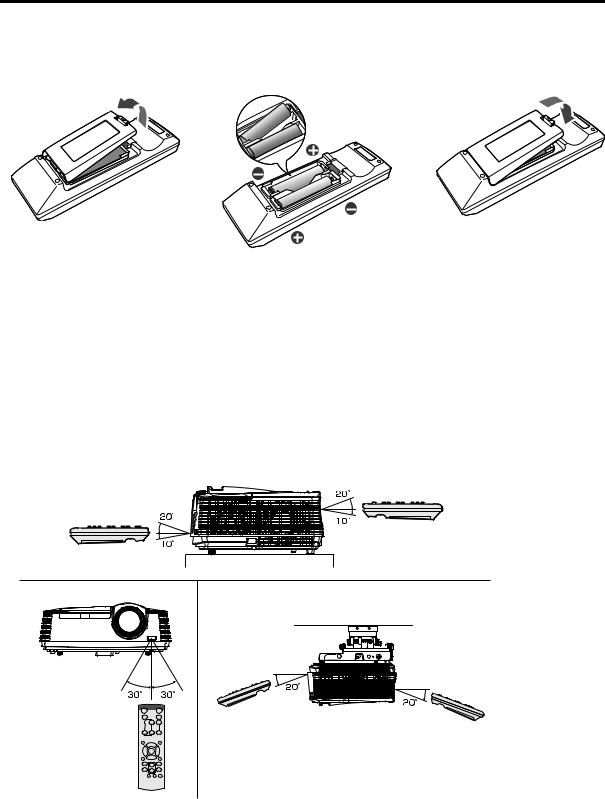
Battery installation
Use two (AA, R6) size batteries.
1.Remove the back cover of the remote control by pushing the battery compartment door in the direction of the arrow.
2.Load the batteries making sure that they are positioned correctly (+ to +, and - to -).
• Load the batteries from - spring side, and make sure to set them tightly.
3.Replace the back cover.
Caution:
•Use of a battery of wrong type may cause explosion.
•Only Carbon-Zinc or Alkaline-Manganese Dioxide type batteries should be used.
•Dispose of used batteries according to your local regulations.
•Batteries may explode if misused. Do not recharge, disassemble, or dispose of in fire.
•Be sure to handle the battery according to the instructions.
•Load the battery with its positive (+) and negative (-) sides correctly oriented as indicated on the remote control.
•Keep batteries out of reach of children and pets.
•Remove the battery, if the remote control is not used for a long time.
•Do not combine a new battery with an old one.
•If the solution of batteries comes in contact with your skin or clothes, rinse with water. If the solution comes in contact with your eyes, rinse them with water and then consult your doctor.
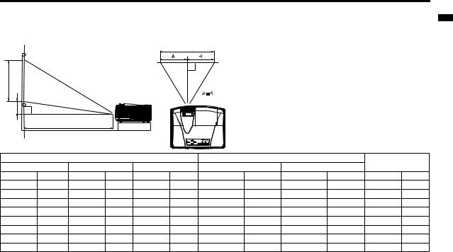
Operation range (of the remote control)
The maximum operation distance of the remote control is about 10 m (or about 32 feet) when the remote control is pointed at the remote control sensor of the projector. When the remote control is pointed to the screen, the distance from the remote control to the projector via the screen should be 5 m or less. However, the operation distance varies depending on the type of the screen used.
Reception angle (vertical)
Reception angle (horizontal) |
Reception angle (vertical), ceiling mount |
Important:
•Do not expose the remote control sensor to direct sunlight or fluorescent. Keep a distance at least 2 m (6.5 feet) between the remote control sensor and the fluorescent light to ensure correct operation of the remote control.
Inverted fluorescent light, if located near the projector, may interfere the remote control.
•When you use the remote control too close to the remote control sensor, the remote control may not work correctly.
EN-8
Installation
Layout of the projector XD600U/XD600U-G
Image size varies depending on the distance between the screen and the projector.
Front projection
|
|
|
|
|
SW |
|
|
|
|
|
|
SH |
|
|
|
|
|
|
|
|
|
|
|
Hd |
|
|
|
|
|
|
|
|
|
|
|
|
|
L |
|
|
|
|
|
|
|
|
|
|
|
|
|
|
|
|
L : Between the screen and the front edge of the projector |
|
|
||
|
|
|
|
|
|
|
Hd : Height of the projected image |
|
|
|
|
|
|
Screen |
|
|
|
|
Distance from the screen : L |
|
|
Hd |
|
Diagonal size |
Width : SW |
Height : SH |
Shortest (WIDE) |
Longest (TELE) |
|
||||||
|
|
||||||||||
inch |
cm |
inch |
cm |
inch |
cm |
inch |
m |
inch |
m |
inch |
cm |
40 |
102 |
32 |
81 |
24 |
61 |
45 |
1.1 |
67 |
1.7 |
3.6 |
9 |
60 |
152 |
48 |
122 |
36 |
91 |
68 |
1.7 |
102 |
2.6 |
5.4 |
14 |
80 |
203 |
64 |
163 |
48 |
122 |
91 |
2.3 |
137 |
3.5 |
7.2 |
18 |
100 |
254 |
80 |
203 |
60 |
152 |
115 |
2.9 |
171 |
4.3 |
9.0 |
23 |
150 |
381 |
120 |
305 |
90 |
229 |
173 |
4.4 |
258 |
6.5 |
13.5 |
34 |
200 |
508 |
160 |
406 |
120 |
305 |
231 |
5.9 |
344 |
8.7 |
18.0 |
46 |
250 |
635 |
200 |
508 |
150 |
381 |
289 |
7.3 |
431 |
10.9 |
22.5 |
57 |
300 |
762 |
240 |
610 |
180 |
457 |
348 |
8.8 |
- |
- |
27.0 |
69 |
•The above figures are approximate and may be slightly different from the actual measurements.
Layout of the projector WD620U/WD620U-G
Image size varies depending on the distance between the screen and the projector.
|
|
Screen Size |
|
|
|
|
Projected Distance : L |
|
|
Hd |
|||
|
|
|
|
|
|
|
|
|
|
|
|
||
16:10 Diagonal Size |
Width : SW |
Height : SH |
Shortest (WIDE) |
Longest (TELE) |
|
|
|
||||||
|
|
|
|
|
|
|
|
|
|
|
|
|
|
inch |
cm |
inch |
|
cm |
inch |
cm |
inch |
m |
inch |
m |
inch |
|
cm |
|
|
|
|
|
|
|
|
|
|
|
|
|
|
40 |
102 |
34 |
|
86 |
21 |
54 |
48 |
1.2 |
72 |
1.8 |
6.2 |
|
16 |
|
|
|
|
|
|
|
|
|
|
|
|
|
|
60 |
152 |
51 |
|
129 |
32 |
81 |
73 |
1.9 |
110 |
2.8 |
9.2 |
|
23 |
|
|
|
|
|
|
|
|
|
|
|
|
|
|
80 |
203 |
68 |
|
172 |
42 |
108 |
98 |
2.5 |
147 |
3.7 |
12.3 |
|
31 |
|
|
|
|
|
|
|
|
|
|
|
|
|
|
100 |
254 |
85 |
|
215 |
53 |
135 |
123 |
3.1 |
184 |
4.7 |
15.4 |
|
39 |
|
|
|
|
|
|
|
|
|
|
|
|
|
|
150 |
381 |
127 |
|
323 |
79 |
202 |
186 |
4.7 |
277 |
7.0 |
23.1 |
|
59 |
|
|
|
|
|
|
|
|
|
|
|
|
|
|
200 |
508 |
170 |
|
431 |
106 |
269 |
248 |
6.3 |
370 |
9.4 |
30.8 |
|
78 |
|
|
|
|
|
|
|
|
|
|
|
|
|
|
250 |
635 |
212 |
|
538 |
132 |
337 |
311 |
7.9 |
463 |
11.8 |
38.5 |
|
98 |
|
|
|
|
|
|
|
|
|
|
|
|
|
|
300 |
762 |
254 |
|
646 |
159 |
404 |
373 |
9.5 |
- |
- |
46.2 |
|
117 |
|
|
|
|
|
|
|
|
|
|
|
|
|
|
•The above figures are approximate and may be slightly different from the actual measurements.
ENGLISH
EN-9
Installation (continued)
When the aspect ratio of the screen is 4:3
When the aspect ratio of the screen is 4:3, the positional relation between the projected image and the screen is as shown on the right. Refer to the following table for installation.
|
|
|
Screen size |
||
|
|
|
|
|
|
|
|
|
|
|
|
SH |
|
|
|
B |
|
|
|
|
|
||
|
|
|
H |
||
|
|
|
|
|
|
|
|
|
|
|
B |
|
|
|
|
|
|
SW=W
When the aspect ratio of the image is 16:10 (WXGA)
|
|
|
Screen Size |
|
|
|
|
Size of Projected Image |
|
|
|
Projected Distance : L |
|
|
|
|||||||
|
|
|
|
|
|
|
|
|
|
|
|
|
|
|
|
|
|
Hd |
||||
4:3 Diagonal |
Width : SW |
Height : SH |
16:10 |
Width : W |
Height : H |
Blank Space : |
Shortest |
Longest |
|
|||||||||||||
|
Size |
Diagonal Size |
|
B |
(Wide) |
(Tele) |
|
|
|
|||||||||||||
|
|
|
|
|
|
|
|
|
|
|
|
|
||||||||||
|
|
|
|
|
|
|
|
|
|
|
|
|
|
|
|
|
|
|
|
|
|
|
inch |
|
cm |
inch |
cm |
inch |
cm |
inch |
cm |
inch |
cm |
inch |
cm |
inch |
|
cm |
inch |
m |
inch |
m |
inch |
|
cm |
|
|
|
|
|
|
|
|
|
|
|
|
|
|
|
|
|
|
|
|
|
|
|
40 |
|
102 |
32 |
81 |
24 |
61 |
38 |
96 |
32 |
81 |
20 |
51 |
2.0 |
|
5 |
45 |
1.1 |
68 |
1.7 |
5.8 |
|
15 |
|
|
|
|
|
|
|
|
|
|
|
|
|
|
|
|
|
|
|
|
|
|
|
60 |
|
152 |
48 |
122 |
36 |
91 |
57 |
144 |
48 |
122 |
30 |
76 |
3.0 |
|
8 |
69 |
1.7 |
103 |
2.6 |
8.7 |
|
22 |
|
|
|
|
|
|
|
|
|
|
|
|
|
|
|
|
|
|
|
|
|
|
|
80 |
|
203 |
64 |
163 |
48 |
122 |
75 |
192 |
64 |
163 |
40 |
102 |
4.0 |
|
10 |
92 |
2.3 |
138 |
3.5 |
11.6 |
|
30 |
|
|
|
|
|
|
|
|
|
|
|
|
|
|
|
|
|
|
|
|
|
|
|
100 |
|
254 |
80 |
203 |
60 |
152 |
94 |
240 |
80 |
203 |
50 |
127 |
5.0 |
|
13 |
116 |
2.9 |
173 |
4.4 |
14.5 |
|
37 |
|
|
|
|
|
|
|
|
|
|
|
|
|
|
|
|
|
|
|
|
|
|
|
150 |
|
381 |
120 |
305 |
90 |
229 |
142 |
359 |
120 |
305 |
75 |
191 |
7.5 |
|
19 |
175 |
4.4 |
261 |
6.6 |
21.8 |
|
55 |
|
|
|
|
|
|
|
|
|
|
|
|
|
|
|
|
|
|
|
|
|
|
|
200 |
|
508 |
160 |
406 |
120 |
305 |
189 |
479 |
160 |
406 |
100 |
254 |
10.0 |
|
25 |
234 |
5.9 |
349 |
8.9 |
29.0 |
|
74 |
|
|
|
|
|
|
|
|
|
|
|
|
|
|
|
|
|
|
|
|
|
|
|
250 |
|
635 |
200 |
508 |
150 |
381 |
236 |
599 |
200 |
508 |
125 |
318 |
12.5 |
|
32 |
293 |
7.4 |
436 |
11.1 |
36.3 |
|
92 |
|
|
|
|
|
|
|
|
|
|
|
|
|
|
|
|
|
|
|
|
|
|
|
300 |
|
762 |
240 |
610 |
180 |
457 |
283 |
719 |
240 |
610 |
150 |
381 |
15.0 |
|
38 |
352 |
8.9 |
- |
- |
43.6 |
|
111 |
|
|
|
|
|
|
|
|
|
|
|
|
|
|
|
|
|
|
|
|
|
|
|
When the aspect ratio of the image is 16:9
|
|
|
Screen Size |
|
|
|
|
|
Size of Projected Image |
|
|
|
Projected Distance : L |
|
|
|
|||||||
|
|
|
|
|
|
|
|
|
|
|
|
|
|
|
|
|
|
|
Hd |
||||
4:3 Diagonal |
Width : SW |
Height : SH |
|
16:9 |
Width : W |
Height : H |
Blank Space : |
Shortest |
Longest |
|
|||||||||||||
|
Size |
Diagonal Size |
|
B |
(Wide) |
(Tele) |
|
|
|
||||||||||||||
|
|
|
|
|
|
|
|
|
|
|
|
|
|||||||||||
|
|
|
|
|
|
|
|
|
|
|
|
|
|
|
|
|
|
|
|
|
|
|
|
inch |
|
cm |
inch |
cm |
inch |
cm |
inch |
|
cm |
inch |
cm |
inch |
cm |
inch |
|
cm |
inch |
m |
inch |
m |
inch |
|
cm |
|
|
|
|
|
|
|
|
|
|
|
|
|
|
|
|
|
|
|
|
|
|
|
|
40 |
|
102 |
32 |
81 |
24 |
61 |
37 |
|
93 |
32 |
81 |
18 |
46 |
3.0 |
|
8 |
44 |
1.1 |
66 |
1.7 |
6.8 |
|
17 |
|
|
|
|
|
|
|
|
|
|
|
|
|
|
|
|
|
|
|
|
|
|
|
|
60 |
|
152 |
48 |
122 |
36 |
91 |
55 |
|
140 |
48 |
122 |
27 |
69 |
4.5 |
|
11 |
67 |
1.7 |
100 |
2.6 |
10.2 |
|
26 |
|
|
|
|
|
|
|
|
|
|
|
|
|
|
|
|
|
|
|
|
|
|
|
|
80 |
|
203 |
64 |
163 |
48 |
122 |
73 |
|
187 |
64 |
163 |
36 |
91 |
6.0 |
|
15 |
90 |
2.3 |
135 |
3.4 |
13.6 |
|
35 |
|
|
|
|
|
|
|
|
|
|
|
|
|
|
|
|
|
|
|
|
|
|
|
|
100 |
|
254 |
80 |
203 |
60 |
152 |
92 |
|
233 |
80 |
203 |
45 |
114 |
7.5 |
|
19 |
113 |
2.9 |
169 |
4.3 |
17.0 |
|
43 |
|
|
|
|
|
|
|
|
|
|
|
|
|
|
|
|
|
|
|
|
|
|
|
|
150 |
|
381 |
120 |
305 |
90 |
229 |
138 |
|
350 |
120 |
305 |
68 |
171 |
11.3 |
|
29 |
170 |
4.3 |
254 |
6.5 |
25.5 |
|
65 |
|
|
|
|
|
|
|
|
|
|
|
|
|
|
|
|
|
|
|
|
|
|
|
|
200 |
|
508 |
160 |
406 |
120 |
305 |
184 |
|
466 |
160 |
406 |
90 |
229 |
15.0 |
|
38 |
228 |
5.8 |
339 |
8.6 |
34.0 |
|
86 |
|
|
|
|
|
|
|
|
|
|
|
|
|
|
|
|
|
|
|
|
|
|
|
|
250 |
|
635 |
200 |
508 |
150 |
381 |
229 |
|
583 |
200 |
508 |
113 |
286 |
18.8 |
|
48 |
285 |
7.2 |
425 |
10.8 |
42.5 |
|
108 |
|
|
|
|
|
|
|
|
|
|
|
|
|
|
|
|
|
|
|
|
|
|
|
|
300 |
|
762 |
240 |
610 |
180 |
457 |
275 |
|
699 |
240 |
610 |
135 |
343 |
22.5 |
|
57 |
342 |
8.7 |
- |
- |
51.1 |
|
130 |
|
|
|
|
|
|
|
|
|
|
|
|
|
|
|
|
|
|
|
|
|
|
|
|
•The above figures are approximate and may be slightly different from the actual measurements.
Front projection, ceiling mounting
For ceiling mounting, you need the ceiling mount kit designed for this projector. Ask a specialist for installation.
For details, consult your dealer.
•The warranty on this projector does not cover any damage caused by use of any non-recommended ceiling mount kit or installation of the ceiling mount kit in an improper location.
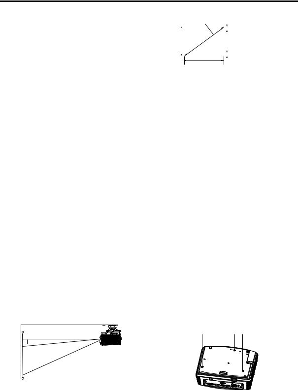
Ceiling Mount Installation
If you wish to install the projector using a ceiling mount, please use the screw holes as the illustration shows.
Important:
•Screws are not included. Please obtain the appropriate screws for your type of ceiling. (M4 diameter)
•It is recommended that you keep a reasonable space between the bracket and the projector to allow for proper heat distribution.
•When using the projector mounted on the ceiling, set IMAGE REVERSE in the INSTALLATION menu to MIRROR INVERT. See page 23.
•When the projector is mounted on the ceiling, images may appear darker than those projected in the case of tabletop mounting. This isn’t a product malfunction.
EN-10
Installation (continued)
Rear projection
Ask a specialist for installation. For details, consult your dealer.
•For rear projection, set IMAGE REVERSE in the INSTALLATION menu to MIRROR. See page 23.
Caution:
•Placing the projector directly on a carpet impairs ventilation by the fans, causing damage or failure. Put a hard board under the projector to facilitate ventilation.
•Place the projector at least 50 cm (or 20 inch) away from the wall to prevent the air inlet grille and the air outlet grilles that emit hot air from being blocked.
•Do not use the projector in the following locations and manners, which may cause fire or electric shock.
•In a dusty or humid place.
•In a sideways or upside-down position.
•Near a heater.
•In an oily, smoky, or damp place such as a kitchen.
•In direct sunlight.
•Where the temperature rises high, such as in a closed car.
•Where the temperature is lower than +41°F (or +5°C) or higher than +95°F (or +35°C ).
Important:
•Do not apply force to the lens, because the lens may be damaged.
•Be sure to use this projector at an altitude of less than 1500 meters.
ENGLISH
EN-11

Basic connections
This projector can be connected with various devices such as a VCR, video camera, videodisc player, and personal computer that have analog RGB output connectors.
Important:
•Make sure that the connected device is turned off before starting connection.
•Plug in the power cords of the projector and the connected devices firmly. When unplugging, hold and pull the plug. Do not pull the cord.
•When the projector and the connected devices are located too close to each other, the projected image may be affected by their interference.
•See the owner’s guide of each device for details about its connections.
Projector + AV device
S-VIDEO IN (option)
VIDEO IN (option)
AUDIO IN-3L (option)
AUDIO IN-3R
to audio output (L)
to audio output (R)
VCR, etc.
to Video output
to S-video output
Important:
•Match the colors of the video and audio plugs on the Audio cable with those of the terminals.
•Speaker output is mono.
Projector + DVD player or HDTV decoder
Some DVD players have an output connector for 3-line fitting (Y, CB, CR). When connecting such DVD player with this projector, use the COMPUTER IN terminal.
Audio cable (option)
DVD player or HDTV decoder
to audio output
BNC - RCA connector (option)
No connection
B  R
R
COMPUTER IN
Mini D-SUB 15-pin - BNC conversion cable (option)
Important:
•The terminal’s names Y, PB, and PR are given as examples of when a HDTV decoder is connected.
•The terminal’s names vary depending on the connected devices.
•Use a Mini D-SUB 15-pin - BNC conversion cable for connection.
•Image may not be projected correctly with some DVD players.
•When connecting a HDTV decoder having RGB output terminals, set COMPUTER INPUT to RGB in the SIGNAL menu.
EN-12
Basic connections (continued)
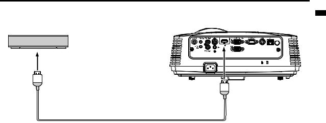
Connection (for video equipment having an HDMI terminal)
Equipment having an
HDMI terminal
to HDMI terminal
HDMI IN
HDMI (with HDMI logo) cable (option)
Important:
•Use a commercially available HDMI (with HDMI logo) cable.
•You don’t have to connect any cable for audio input. You can input video and audio using an HDMI cable only.
•When HDMI audio isn’t output, it may be output by turning off the power of the video equipment with the projector and the video equipment connected to each other and then turning back on the power.
•Some cables may not be connected correctly depending on the size and shape of their connectors.
ENGLISH
EN-13
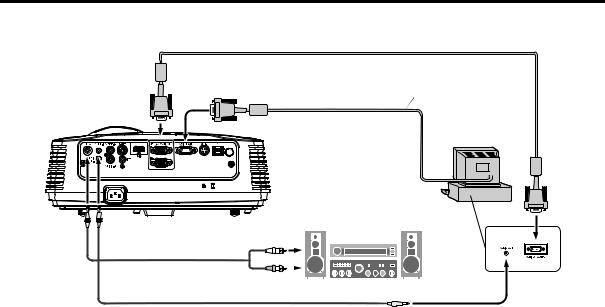
Basic connections (continued)
Projector + Computer
For computer with Mini D-SUB
RGB cable for PC
Necessary when outputting to both a PC monitor and the projector.
COMPUTER IN
RGB cable for PC (option)
MONITOR OUT
Computer
to monitor port
AUDIO |
AUDIO IN-1 |
OUT |
or IN-2 |
Audio cable (option)
|
|
|
|
|
|
PC audio cable (option) |
|
to PC audio output |
|||
|
|||||
|
|||||
For analog connection:
1.Connect one end of the supplied RGB cable to the COMPUTER IN terminal (1, 2) of the projector.
2.Connect the other end of the RGB cable to the monitor port of the computer.
For monitor connection:
Connect the RGB cable from the monitor to the MONITOR OUT terminal of the projector.
•Images may not be displayed correctly depending on the type of the input signal. See the instruction manual of the monitor.
•Signals are coming from the COMPUTER IN terminal (1 or 2) of the projector.
•MONITOR OUT is not output during the STANDBY state.
•When signals are coming from both COMPUTER IN terminals (1, 2), images are projected from the terminal (1 or 2) currently or last selected in the projector's menu.
Important:
•When you use a longer RGB cable instead of the provided cable, the image may not be projected correctly.
•Some computers require additional connectors or analog RGB output adapters to be connected with this projector. Contact your dealer for further information.
•This projector uses stereo mini jack for its audio input. Check the type of the audio output terminal of the connected computer and prepare a proper cable for connection. Some computers don’t have the audio output terminal.
•Speaker output is mono.
•When the audio cable is connected to the AUDIO OUT terminal, the speaker output is muted.
For Macintosh
•If your Macintosh has no video port, a monitor output adapter is required. Contact your dealer for further information.
•Some Macintoshes require a MAC adapter for the RGB cable for connection with this projector. Contact your dealer for further information.
About DDC
The COMPUTER/COMPONENT VIDEO IN-1 terminal of this projector complies with the DDC 1/2B standard. When a computer supporting this standard is connected to this terminal, the computer will automatically load the information from this projector and prepare for output of appropriate images.
•After connecting a computer supporting this standard to this terminal, plug the power cord of the projector in the wall outlet first, and then boot up the computer.
EN-14
Loading...