


WS-65905
Mitsubishi Electronics WS-65905, WS-55905, VS-60805, WT-46805, WS-73905 User Manual
...
THE BIG SCREEN COMPANY
TM
PROJECTION TELEVISION
PROJECTION TELEVISION
OWNER’S GUIDE
OWNER’S GUIDE
1
2
3
5
6
789
0
SQV
QV
4
POWER
PAUSE
REC
FF/FWDREW/REV
PLAY
STOP
TV
AUDIO
CABLE/DBS/DTV
DVD
VOLUME
INPUT
SLEEP
VIDEO
AUDIO
MUTE
CHANNEL
VCR
SUB
CANCEL
MENU
ENTER
GUIDE
PIP/POP
FORMAT
PIP CH
PIP INPUT
EXCH
HOME
INFO
WT-46805
WS-55805
WS-55905
WS-65905
WS-73905
VS-50805
VS-60805
CAUTION: TO REDUCE THE RISK OF ELECTRIC SHOCK, DO NOT REMOVE COVER
(OR BACK).
NO USER-SERVICEABLE PARTS INSIDE.
REFER SERVICING TO QUALIFIED SERVICE PERSONNEL.
The lightning flash with arrowhead symbol within an equilateral triangle is intended to alert
the user to the presence of uninsulated “dangerous voltage” within the product’s enclosure
that may be of sufficient magnitude to constitute a risk of electric shock.
Warning: To avoid permanently imprinting a fixed image onto your TV screen, please do not display the same
stationary images on the screen for more than 15% of your total TV viewing in one week. Examples of stationary
images are letterbox top/bottom bars from DVD disc or other video sources, side bars when showing standard TV
pictures on widescreen TV’s, stock market reports, video game patterns, station logs, web sites or stationary com-
puter images. Such patterns can unevenly age the picture tubes causing permanent damage to the TV. Please see
page 56 for a detailed explanation.
WARNING:
TO REDUCE THE RISK OF FIRE OR ELECTRIC SHOCK, DO NOT EXPOSE THIS APPLIANCE TO RAIN OR
MOISTURE.
CAUTION:
TO PREVENT ELECTRIC SHOCK, MATCH WIDE BLADE OF PLUG TO WIDE SLOT, FULLY INSERT.
NOTE TO CATV SYSTEM INSTALLER:
THIS REMINDER IS PROVIDED TO CALL THE CATV SYSTEM INSTALLER’S ATTENTION TO ARTICLE 820-40 OF
THE NEC THAT PROVIDES GUIDELINES FOR PROPER GROUNDING AND, IN PARTICULAR, SPECIFIES THAT
THE CABLE GROUND SHALL BE CONNECTED TO THE GROUNDING SYSTEM OF THE BUILDING, AS CLOSE
TO THE POINT OF CABLE ENTRY AS PRACTICAL.
RISK OF ELECTRIC SHOCK
DO NOT OPEN
Note: This equipment has been tested and found to comply with the limits for a Class B digital
device, pursuant to part 15 of the FCC Rules. These limits are designed to provide reasonable
protection against harmful interference in a residential installation. This equipment generates, uses
and can radiate radio frequency energy and, if not installed and used in accordance with the instruc-
tions, may cause harmful interference to radio communications. However, there is no guarantee that
interference will not occur in a particular installation. If this equipment does cause harmful interfer-
ence to radio or television reception, which can be determined by turning the equipment off and on,
the user is encouraged to try to correct the interference by one or more of the following measures:
• Reorient or relocate the receiving antenna
• Increase the separation between the equipment and receiver
• Connect the equipment into an outlet on a circuit different from
that to which the receiver is connected
• Consult the dealer or an experienced radio/TV technician for help
Changes or modifications not expressly approved by Mitsubishi could void the user’s authority to operate
this equipment.
CAUTION
The exclamation point within an equilateral triangle is intended to alert the user to the
presence of important operating and maintenance (servicing) instructions in the literature
accompanying the appliance.

Contents
Important Safeguards __________________________________________________ 5
Instructions on safety and proper handling of your Mitsubishi television
Special Features _______________________________________________________ 7
Distinctive features, items included with your Mitsubishi television and hookup guidelines
Shortcuts _____________________________________________________________ 8
A quick reference list
Connections___________________________________________________________ 9
Basic hookups to an antenna, cable, components, IR emitter and HDTV receiver
Remote Control Functions _____________________________________________ 18
Features of the remote control, programming to work with other audio and video products,
explanation of buttons, controlling the sleep timer
The Menu System ______________________________________________ 25
Explanation of the on-screen menu system and all menu screens and how to use the menus
Special Remote Control Functions ______________________________________ 59
Using the remote with other products, using the PIP (Picture-in-Picture), Side-by-side
and POP (Picture-outside-Picture) features, Formats, Mitsubishi’s Active AV Network
and Home Theater IR system control
Control Panel Functions________________________________________________ 68
Explanation of the front control panel buttons and the back panel terminals
Troubleshooting _______________________________________________________ 73
Common problems, notes on caring and cleaning for your Mitsubishi television and how to obtain
service
Appendices____________________________________________________________ 77
Diamond Shield
TM
removal and installation, remote control programming codes, bypassing
the parent lock, INPUT-3 component video and HDTV video connection compatibility

5
Important Safeguards
Please read all these instructions regarding your television set and retain for future refer-
ence. Follow all warnings and instructions marked on the television.
1. Read, Retain and Follow Instructions
Read all safety and operating instructions before operating the appliance. Retain the safety and operating
instructions for future reference. Follow all operating and use instructions.
2. Heed Warnings
Adhere to all warnings on the appliance and in the operating instructions.
3. Cleaning
Unplug this TV receiver from the wall outlet before cleaning. Do not use liquid or aerosol cleaners.
Cleaners can permanently damage the cabinet or screen. Use a damp cloth for cleaning.
4. Attachments and Equipment
Never add any attachments and/or equipment without approval of the manufacturer as such additions
may result in the risk of fire, electric shock or other personal injury.
5. Water and Moisture
Do not use this TV receiver where contact with or immersion in water is possible. Do not use near bath
tubs, wash bowls, kitchen sinks, laundry tubs, swimming pools, etc.
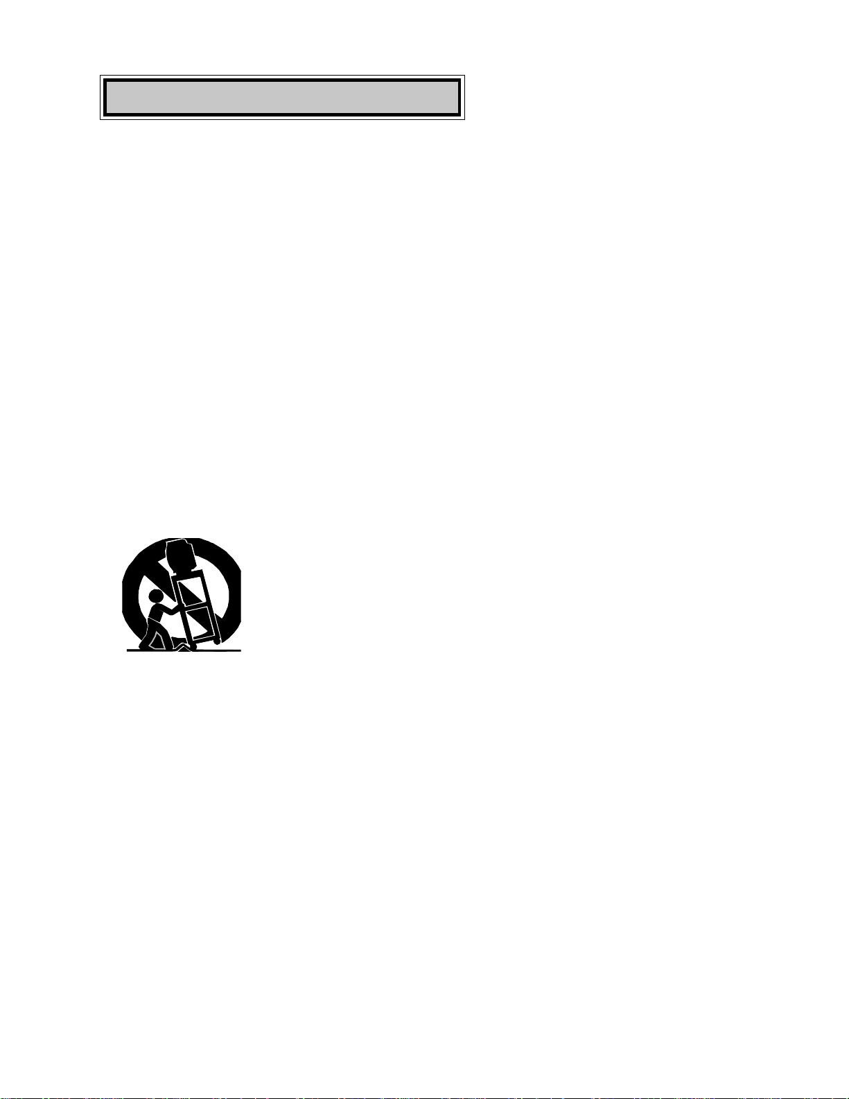
6. Accessories
Do not place this TV receiver on an unstable cart, stand, tripod, bracket, or table. The TV receiver may
fall, causing serious injury to a child or adult, and serious damage to the appliance. Use only
with a cart, stand, tripod, bracket, or table recommended by the manufacturer, or sold
with the TV receiver. Any mounting of the appliance should follow the manufacturer’s
instructions, and should use a mounting accessory recommended by the manufacturer.
An appliance and cart combination should be moved with care. Quick stops, excessive
force, and uneven surfaces may cause the appliance and cart combination to overturn.
7. Ventilation
Slots and openings in the cabinet are provided for ventilation and to ensure reliable operation of the TV
receiver and to protect it from overheating. Do not block these openings or allow them to be blocked
by placing the TV receiver on a bed, sofa, rug, or other similar surface. Nor should it be placed over a
radiator or heat register. If the TV receiver is to be placed in a rack or bookcase, ensure that there is
adequate ventilation and that the manufacturer’s instructions have been adhered to.
8. Power Source
This TV receiver should be operated only from the type of power source indicated on the marking label.
If you are not sure of the type of power supplied to your home, consult your appliance dealer or local
power company.
9. Grounding or Polarization
This TV receiver is equipped with a polarized alternating current line plug having one blade wider than
the other. This plug will fit into the power outlet only one way. If you are unable to insert the plug fully
into the outlet, try reversing the plug. If the plug should still fail to fit, contact your electrician to replace
your obsolete outlet. Do not defeat the safety purpose of the polarized plug.
10. Power-Cord Protection
Power-supply cords should be routed so that they are not likely to be walked on or pinched by items
placed upon or against them, paying particular attention to cords at plugs, convenience receptacles, and
the point where they exit from the appliance.
6
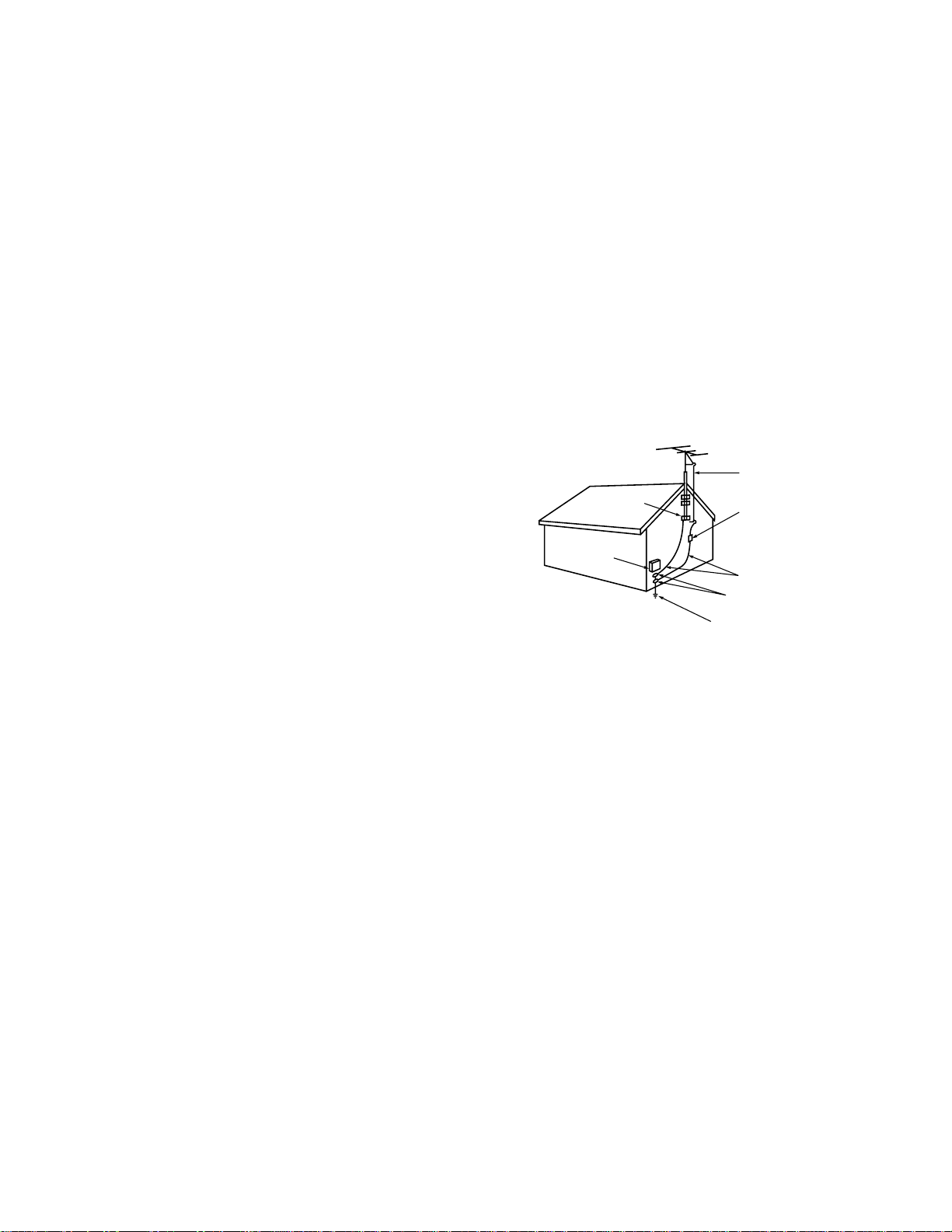
ANTENNA
LEAD IN WIRE
ANTENNA
DISCHARGE UNIT
(NEC SECTION 810-20)
GROUNDING
CONDUCTORS
(NEC SECTION 810-21)
GROUND CLAMPS
POWER SERVICE GROUNDING
ELECTRODE SYSTEM
(NEC ART 250, PART H)
GROUND CLAMP
ELECTRIC
SERVICE
EQUIPMENT
NEC — NATIONAL ELECTRICAL CODE
EXAMPLE OF ANTENNA GROUNDING
11. Lightning
For added protection for this TV receiver during a lightning storm, or when it is left unattended and unused for
long periods of time, unplug it from the wall outlet and disconnect the antenna or cable system. This will prevent
damage to the TV receiver due to lightning and power-line surges.
12. Power Lines
An outside antenna system should not be located in the vicinity of overhead power lines or other electric light
or power circuits, or where it can fall into such power lines or circuits. When installing an outside antenna
system, extreme care should be taken to keep from touching such power lines or circuits as contact with them
might be fatal.
13. Overloading
Do not overload wall outlets and extension cords as this can result in a risk of fire or electric shock.
14. Object and Liquid Entry
Never push objects of any kind into this TV receiver through openings as they may touch dangerous voltage
points or short-out parts that could result in a fire or electric shock. Never spill liquid of any kind on the TV
receiver.
15. Outdoor Antenna Grounding
If an outside antenna or cable system is connected to the TV
receiver, be sure the antenna or cable system is grounded so as
to provide some protection against voltage surges and built-up
static charges.
Section 810 of the National Electrical Code, ANSI/NFPA No. 70-
1984, provides information with respect to proper grounding of
the mast and supporting structure, grounding of the lead in wire
to an antenna discharge unit, size of grounding conductors,
location of antenna discharge unit, connection to grounding
electrodes, and requirements for the grounding electrode.
16. Servicing
Do not attempt to service this TV receiver yourself as opening or removing covers may expose you to danger-
ous voltage or other hazards. Refer all servicing to qualified service personnel.
17. Damage Requiring Service
Unplug this TV receiver from the wall outlet and refer servicing to qualified service personnel under the follow-
ing conditions: (a)
When the power-supply cord or plug is damaged. (b) If
liquid has been spilled, or objects have fallen into the TV receiver. (c) If the TV
receiver has been exposed to rain or water. (d) If the TV
receiver does not operate normally by following the operating instructions, adjust only those controls that are
covered by the operating instructions as an improper adjustment of other controls may result in damage and will
often require extensive work by a qualified technician to restore the TV receiver to its normal operation.
(e) If the TV receiver has been dropped or the cabinet has been damaged. (f)
When the TV receiver exhibits a distinct change in performance — this indicates a need for service.
18. Replacement Parts
When replacement parts are required, be sure the service technician has used replacement parts specified by the
manufacturer or have the same characteristics as the original part. Unauthorized substitutions may result in fire,
electric shock or other hazards.
19. Safety Check
Upon completion of any service or repairs to this TV receiver, ask the service technician to perform safety
checks to determine that the TV receiver is in safe operating condition.
7
Special Features
IMPORTANT
IMPORTANT
To maximize your system for its best
performance, your dealer can help you
customize hookups and sell you any addi-
tional connection accessories that may be
needed for your individual equipment.
Choosing a Hookup
The connections shown in this book are general. Cable systems as well as individual audio and/
or video components can vary from those shown here. The first diagrams show basic connec-
tions to antenna or cable systems. After you have completed these, you can then connect any
additional components (stereo, DVD, AV receiver, etc.).
◊ HDTV Upgradeable - with the use of an optional HDTV receiver,
your television can display High Definition pictures
◊ Wide Screen Television
- displays pictures in a widescreen 16:9 aspect
ratio for models WT-46805, WS-55805, WS-55905, WS-65905 and WS-73905
◊ Wide Screen Formats
- for displaying anamorphic DVDs on models
VS-50805 and VS-60805
◊␣ IRIS™ - room sensor that automatically adjusts brightness and contrast
◊ Multibrand Remote Control - use one remote control for many
audio/video components
1
2
3
5
6
789
0
SQV
QV
4
POWER
HOME
PAUSE
REC
FF/FWDREW/REV
PLAY
STOP
VOLUME
INFO
CANCEL
MENU
PIP/POP
FORMAT
PIP CH
INPUT
SLEEP
VIDEO
AUDIO
MUTE
CHANNEL
ENTER
PIP INPUT
EXCH
GUIDE
TV
AUDIO
CABLE/DBS/DTV
DVD
VCR
SUB
2 AAA
batteries
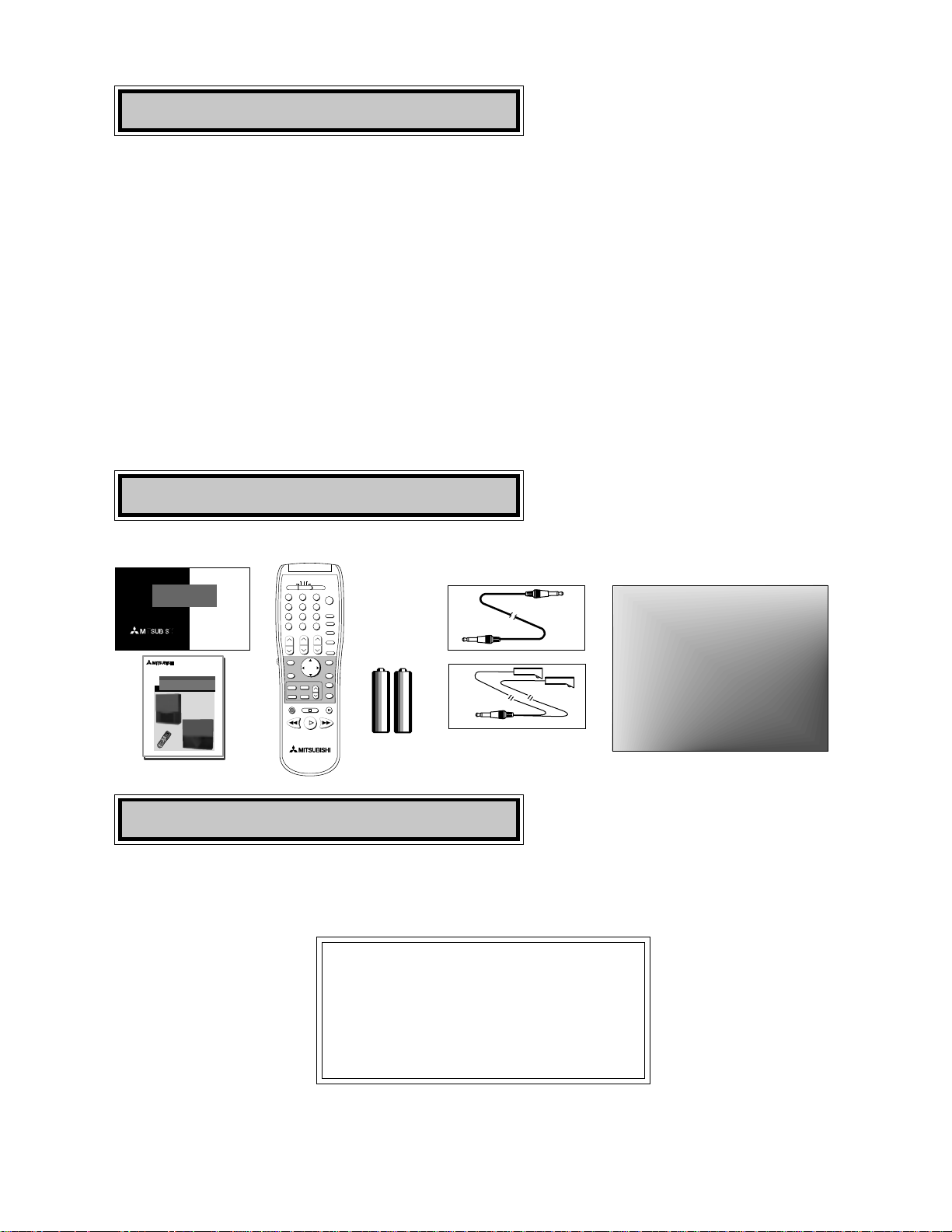
Unpacking Your TV
Diamond Shield (may already be installed)
The following items are included with your new TV:
THE BIG SCREEN COMPANY
TM
PRODUCT
REGISTRATION
Send this
card in to
register your
purchase
THE BIG SCREEN COMPANY
TM
PROJECTION TELEVISION
OWNER'S GUIDE
PROJECTION TELEVISION
OWNER'S GUIDE
VS-50805
VS-60805
WT-46805
WS-55805
WS-55905
WS-65905
WS-73905
1
2
3
5
6
789
0
S
Q
V
Q
V
4
P
O
W
E
R
P
A
U
S
E
R
E
C
F
F
/
F
W
D
R
E
W
/
R
E
V
P
L
A
Y
S
T
O
P
TV
AUDIO
C
A
B
L
E
/
D
B
S
/
D
T
V
D
V
D
V
O
L
U
M
E
I
N
P
U
T
S
L
E
E
P
V
ID
E
O
A
U
D
I
O
M
U
T
E
C
H
A
N
N
E
L
VCR
S
U
B
CANCEL
MENU
ENTER
GUIDE
PIP/POP
FORMAT
PIP CH
PIP INPUT
EXCH
H
O
M
E
I
N
F
O
Active A/V Network Cable
IR Emitter Cable

8
Shortcuts
◊ Connecting the TV to an antenna or wall outlet cable - page 9
◊ Connecting an HD-1080 receiver - page 15
◊ Remote control functions - pages 18-19
◊ Menu screen summaries - pages 26-28
◊ Setup Menu - pages 29-35
◊ Setting the V-Chip parent lock - pages 44-48
◊ Using PIP and POP features - page 60
◊ Troubleshooting - page 73
◊ DVD component video and HDTV video connection
compatibility - page 83
9
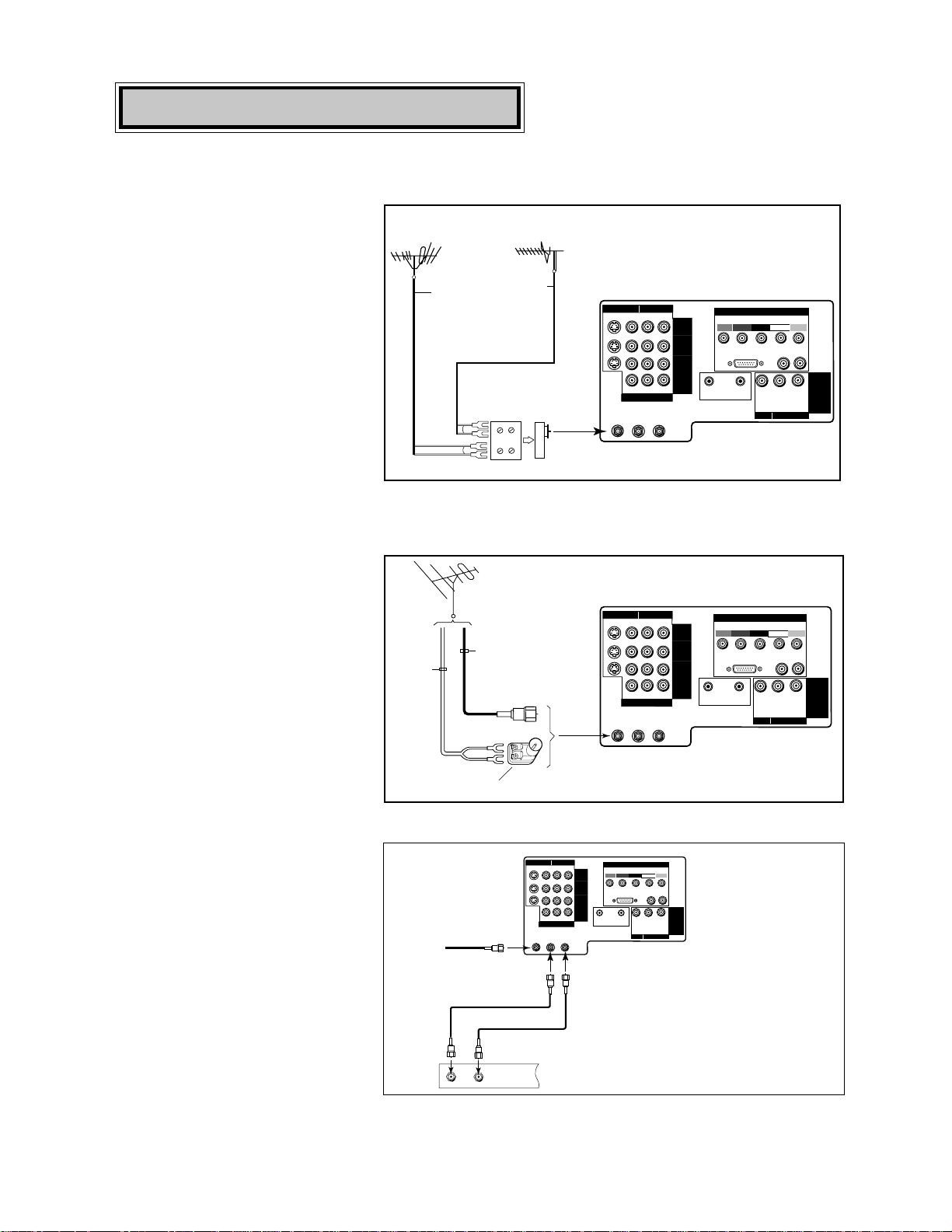
For antenna with twin flat leads
External
Antenna
or Cable
Back
Side
Flat Twin Lead
UHF Antenna
(Channels 14-69)
VHF Antenna
(Channels 2-13)
300 Ohm to
75 Ohm
Combiner
Flat Twin Lead
TV back panel
UHF
VHF
ANT-B
LOOP
OUT
ANT-A
S-VIDEO V L
R
(MONO)
YCrCb
VIDEO AUDIO
INPUT-1
INPUT-2
INPUT-3
HDTV VIDEO
Y
Pr
H V
HDTV CONTROL
HDTV AUDIO
LR
(MONO)
VL
R
(MONO)
IR
HOME
THEATER
ACTIVE A/V
NETWORK
MONITOR
OUTPUT
VIDEO AUDIO
DVD VIDEO
HIGH-DEFINITION INTERFACE
Pb
Separate UHF and VHF antennas
1. Connect the UHF and VHF
antenna leads to the UHF/VHF
combiner.
2. Push the combiner onto ANT-A
on the TV back panel.
300 Ohm Flat
Twin Lead
Optional 300 Ohm to 75 Ohm
Matching Transformer
75 Ohm
Coaxial Cable
TV back panel
ANT-B
LOOP
OUT
ANT-A
S-VIDEO V L
R
(MONO)
YCrCb
VIDEO AUDIO
INPUT-1
INPUT-2
INPUT-3
HDTV VIDEO
Y
Pr
H V
HDTV CONTROL
HDTV AUDIO
LR
(MONO)
VL
R
(MONO)
IR
HOME
THEATER
ACTIVE A/V
NETWORK
MONITOR
OUTPUT
VIDEO AUDIO
DVD VIDEO
HIGH-DEFINITION INTERFACE
Pb
Twin lead antenna or wall outlet cable
For cable or antenna with
coaxial lead
TV to Antenna or Wall Outlet Cable
Connections
1. Connect the incoming cable to
ANT-A on the TV back panel.
2. Connect two coaxial cables as
follows:
• One from LOOP-OUT on the TV
back panel to IN on the back of
the cable box.
• One from OUT on the back of
the cable box to ANT-B on the
TV back panel.
ANT-B
LOOP
OUT
ANT-A
S-VIDEO V L
R
(MONO)
YCrCb
VIDEO AUDIO
INPUT-1
INPUT-2
INPUT-3
HDTV VIDEO
Y
Pr
H V
HDTV CONTROL
HDTV AUDIO
LR
(MONO)
VL
R
(MONO)
IR
HOME
THEATER
ACTIVE A/V
NETWORK
MONITOR
OUTPUT
VIDEO AUDIO
DVD VIDEO
HIGH-DEFINITION INTERFACE
Pb
OUT
Cable Box
back panel section
TV back panel
IN
Incoming
Cable
1. Connect the 300 ohm twin leads
to the transformer.
2. Push the 75 ohm side of the
transformer onto ANT-A on the
TV back panel.
Connect the incoming cable
to ANT-A on the TV back
panel.
Connection of TV to Cable Box
10
Audio Video Connections
1. Connect a video cable from
VIDEO,
OUT on the VCR back panel to VIDEO,
INPUT-1 or INPUT-2 on the TV back
panel.
• If you have a S-VHS VCR, follow the
same steps, using the S-Video terminals
on the VCR and TV.
2. Connect a set of audio cables from
AUDIO, OUT on the VCR back panel
to AUDIO, INPUT-1or INPUT-2 on the
TV back panel. The red cable connects
to the R (right) channel and the white
cable connects to the L (left). If your
VCR is non-stereo, connect only the L
(left) cable.
ANT-B
LOOP
OUT
ANT-A
S-VIDEO V L
R
(MONO)
YCrCb
VIDEO AUDIO
INPUT-1
INPUT-2
INPUT-3
HDTV VIDEO
Y
Pr
H V
HDTV CONTROL
HDTV AUDIO
LR
(MONO)
VL
R
(MONO)
IR
HOME
THEATER
ACTIVE A/V
NETWORK
MONITOR
OUTPUT
VIDEO AUDIO
DVD VIDEO
HIGH-DEFINITION INTERFACE
Pb
TV back panel
IN
OUT
Antenna
AUDIO OUT
AUDIO IN
VIDEO OUT
(Y/C)
MONITOR
1
L
R
L
R
1
2
VCR back panel
If your VCR has a video channel ON/OFF switch, set to OFF.
White
Red
W
h
i
t
e
R
e
d
Attach
only
one
cable
type
Attach
only
one
cable
type
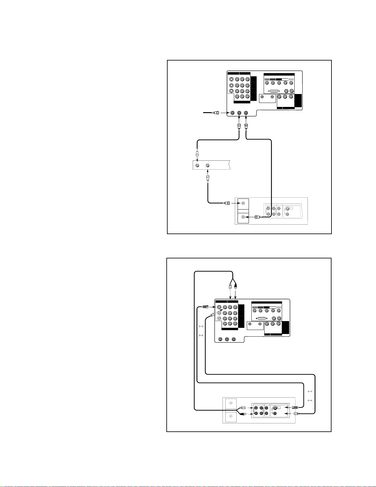
Connection of TV to VCR and Cable Box
ANT-B
LOOP
OUT
ANT-A
S-VIDEO V L
R
(MONO)
YCrCb
VIDEO AUDIO
INPUT-1
INPUT-2
INPUT-3
HDTV VIDEO
Y
Pr
H V
HDTV CONTROL
HDTV AUDIO
LR
(MONO)
VL
R
(MONO)
IR
HOME
THEATER
ACTIVE A/V
NETWORK
MONITOR
OUTPUT
VIDEO AUDIO
DVD VIDEO
HIGH-DEFINITION INTERFACE
Pb
TV back panel
Incoming Cable
Cable Box
Rear Terminals
OUT
IN
IN
OUT
Antenna
AUDIO OUT
AUDIO IN
VIDEO OUT
(Y/C)
MONITOR
1
L
R
L
R
1
2
VCR back panel
If your VCR has a video channel
ON/OFF switch, set to OFF.
1. Connect the incoming cable to ANT-A
on the TV back panel.
2. Connect three coaxial cables as fol-
lows:
• One from LOOP-OUT on the TV back
panel to IN on the back of the cable
box.
• One from OUT on the back of the
cable box to ANTENNA IN on the
VCR back panel.
• One from ANTENNA OUT on the
VCR back panel to ANT-B on the TV
back panel.
11
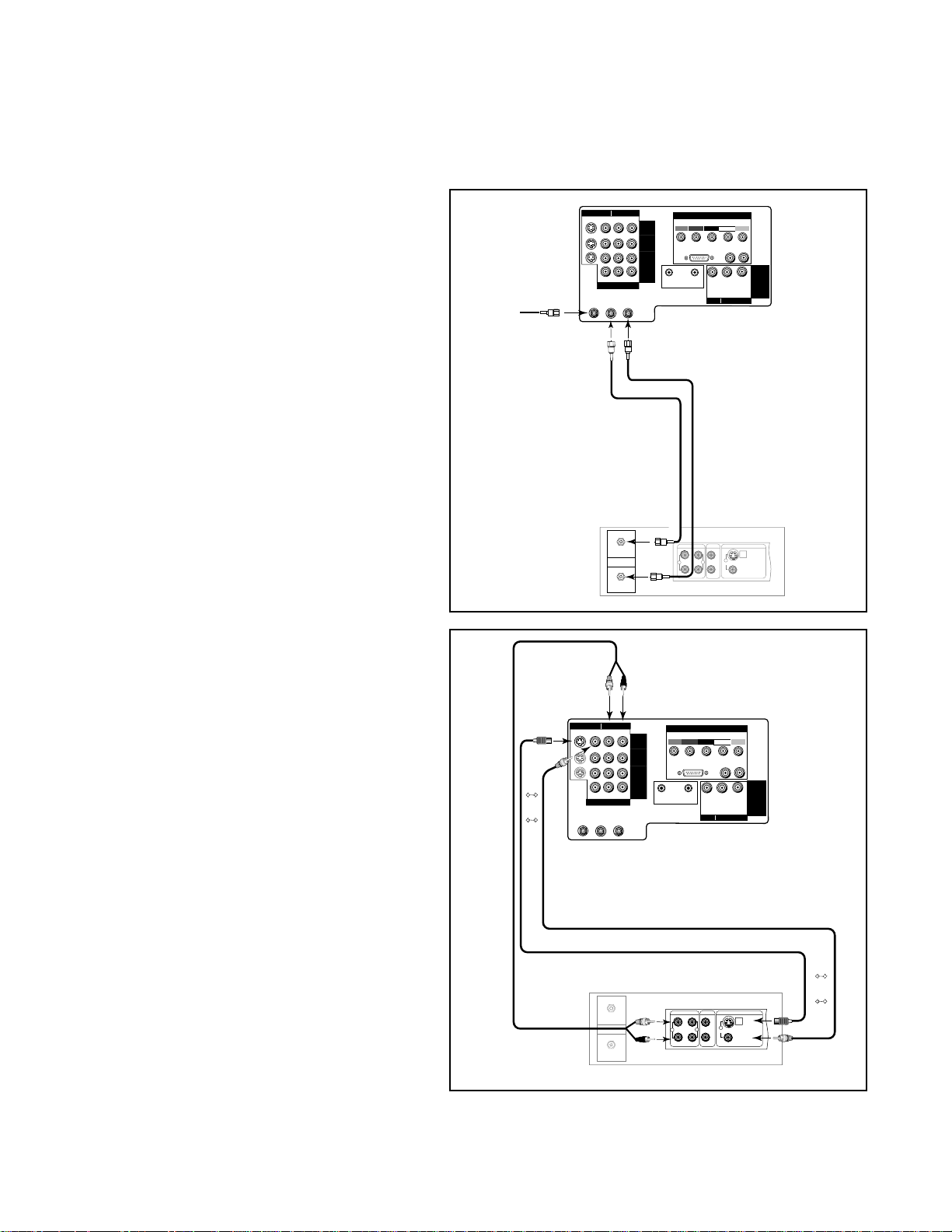
Connection of TV to VCR and Antenna or
Wall Outlet Cable
ANT-B
LOOP
OUT
ANT-A
S-VIDEO V L
R
(MONO)
YCrCb
VIDEO AUDIO
INPUT-1
INPUT-2
INPUT-3
HDTV VIDEO
Y
Pr
H V
HDTV CONTROL
HDTV AUDIO
LR
(MONO)
VL
R
(MONO)
IR
HOME
THEATER
ACTIVE A/V
NETWORK
MONITOR
OUTPUT
VIDEO AUDIO
DVD VIDEO
HIGH-DEFINITION INTERFACE
Pb
TV back panel
Incoming Cable
IN
OUT
Antenna
AUDIO OUT
AUDIO IN
VIDEO OUT
(Y/C)
MONITOR
1
L
R
L
R
1
2
VCR back panel
If your VCR has a video channel
ON/OFF switch, set to OFF.
Audio/Video Connections
1. Connect a video cable from VIDEO, OUT
on the VCR back panel to VIDEO, INPUT-1
or INPUT-2 on the TV back panel (INPUT-
1 shown).
• If you have a S-VHS VCR, follow the same
steps, using the S-Video terminals on the
VCR and TV.
2. Connect a set of audio cables from AU-
DIO OUT on the VCR back panel to
AUDIO, INPUT-1 or INPUT-2 on the TV
back panel. The red cable connects to the
R (right) channel and the white cable
connects to the L (left). If your VCR is
non-stereo, only connect the L (left) cable
(Input-1 shown).
Antenna/Cable Connections
1. Connect the incoming cable to ANT-A on
the TV back panel.
2. Connect two coaxial cables as follows:
• One from LOOP-OUT on the TV back
panel to ANTENNA IN on the VCR back
panel.
• One from VCR back panel ANTENNA OUT
to ANT-B on the TV back panel.
ANT-B
LOOP
OUT
ANT-A
S-VIDEO V L
R
(MONO)
YCrCb
VIDEO AUDIO
INPUT-1
INPUT-2
INPUT-3
HDTV VIDEO
Y
Pr
H V
HDTV CONTROL
HDTV AUDIO
LR
(MONO)
VL
R
(MONO)
IR
HOME
THEATER
ACTIVE A/V
NETWORK
MONITOR
OUTPUT
VIDEO AUDIO
DVD VIDEO
HIGH-DEFINITION INTERFACE
Pb
TV back panel
IN
OUT
Antenna
AUDIO OUT
AUDIO IN
VIDEO OUT
(Y/C)
MONITOR
1
L
R
L
R
1
2
VCR back panel
If your VCR has a video channel ON/OFF switch, set to OFF.
White
Red
W
h
i
t
e
R
e
d
Attach
only
one
cable
type
Attach
only
one
cable
type
12
ANT-B
LOOP
OUT
ANT-A
S-VIDEO V L
R
(MONO)
YCrCb
VIDEO AUDIO
INPUT-1
INPUT-2
INPUT-3
HDTV VIDEO
Y
Pr
H V
HDTV CONTROL
HDTV AUDIO
LR
(MONO)
VL
R
(MONO)
IR
HOME
THEATER
ACTIVE A/V
NETWORK
MONITOR
OUTPUT
VIDEO AUDIO
DVD VIDEO
HIGH-DEFINITION INTERFACE
Pb
Red Lead
White Lead
Red Lead
Audio system back panel section
OUTOUT
OUT
ININININ
SUBWOOFER
(MONO)
CD
AUX TAPE
1
TAPE
2
L
R
TV back panel
White Lead
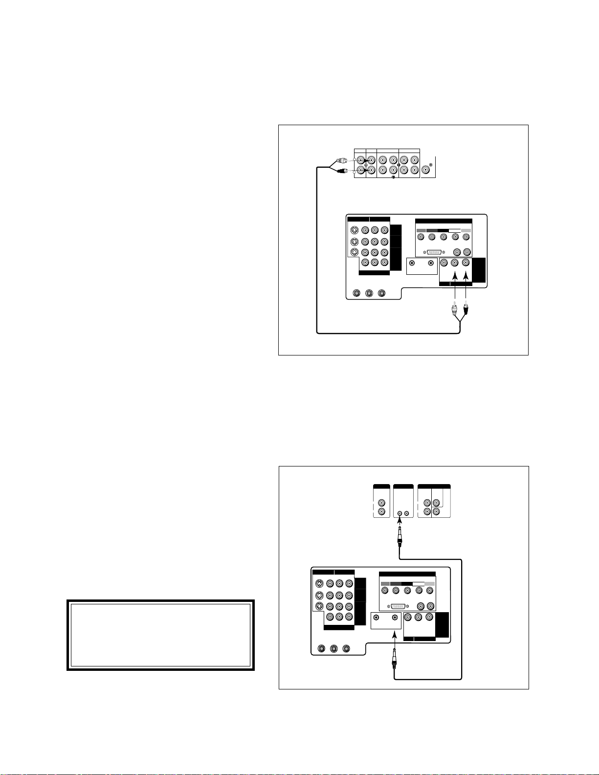
Connection of TV to Stereo Audio System
1. Connect the audio cables from AUDIO,
MONITOR OUTPUT on the TV back panel to
TV IN or AUX IN terminals on the back of the
audio system. The red cable connects to the R
(right) channel and the white cable connects to
the L (left) channel.
2. Turn off the TV’s speakers through the AV
CONNECTION Menu (pages 32-34).
3. Set the audio system’s input to the TV or AUX
position to hear the TV's audio through your
stereo system.
Connection of TV to the Active A/V Network
To control your Mitsubishi audio and/or video products with one remote control
Connect the A/V network cable from ACTIVE
A/V NETWORK on the TV back panel to IN
on the back of a Mitsubishi VCR that has A/V
network terminal.
Turn the ACTIVE A/V NETWORK on through
the AV CONNECTION menu (pages 32-34).
ANT-B
LOOP
OUT
ANT-A
S-VIDEO V L
R
(MONO)
YCrCb
VIDEO AUDIO
INPUT-1
INPUT-2
INPUT-3
HDTV VIDEO
Y
Pr
H V
HDTV CONTROL
HDTV AUDIO
LR
(MONO)
VL
R
(MONO)
IR
HOME
THEATER
ACTIVE A/V
NETWORK
MONITOR
OUTPUT
VIDEO AUDIO
DVD VIDEO
HIGH-DEFINITION INTERFACE
Pb
Mitsubishi Component back panel section
PREOUT
A/V NETWORK
INPUT
REAR CENTER
SUB
WOOFER
IN OUT
L
R
L
R
TV back panel
IMPORTANT IMPORTANT
IMPORTANT IMPORTANT
IMPORTANT
IMPORTANT IMPORTANT
IMPORTANT IMPORTANT
IMPORTANT
Check the Owner's Guide of your
added Mitsubishi components to
ensure the best possible connections.
13
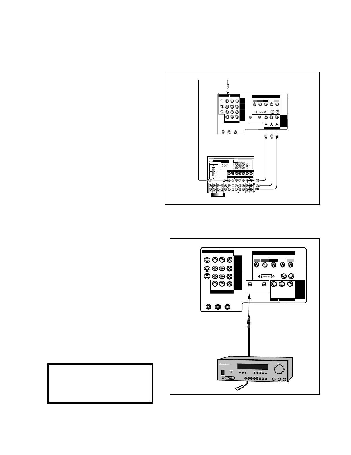
Connection of TV to a Mitsubishi AV Receiver Infrared
Emitter (IR) for Home Theater Control
1. Connect the IR emitter cable to IR HOME
THEATER on the back of the television.
2. Place the IR emitter cable under or along side
of the AV receiver. Place the IR lens directly
in front of the infrared location of the AV
receiver. Infrared locations are usually on the
front glass section of the receiver.
3. Place the unused transmitter in an out-of-the-
way location.
4. For permanent installation of the IR emitter
cable, use the included adhesive tape to
secure the bottom of the emitter to the
anchoring object you choose.
TV back panel
Mitsubishi
AV Receiver
ANT-B
LOOP
OUT
ANT-A
S-VIDEO V L
R
(MONO)
YCrCb
VIDEO AUDIO
INPUT-1
INPUT-2
INPUT-3
HDTV VIDEO
Y
Pr
H V
HDTV CONTROL
HDTV AUDIO
LR
(MONO)
VL
R
(MONO)
IR
HOME
THEATER
ACTIVE A/V
NETWORK
MONITOR
OUTPUT
VIDEO AUDIO
DVD VIDEO
HIGH-DEFINITION INTERFACE
Pb
ANTENNA
OFF
ON
AUTO
STANDBY
S - VIDEO
CDAUX
TAPE
1
TAPE
2
AM
300Ω
FM
R
VCR 1 VCR 2 TV DVD
OUT
IN
PRE OUT
AUDIO
AVIS
RISQUE DE CHOC ELECTRIQUE
NE PAS ENLEVER
U
L
R
U
L
R
C
AUDIO EQUIPMENT
UL FILE No. E51519
LISTED
857C
ININ IN OUT IN OUT IN OUT IN IN IN
MONITOR VCR2 TV DVDVCR 1
OUT IN OUT IN IN IN
MONITOR VCR2 TV DVDVCR 1
OUT
OUT IN OUT IN IN INOUT
VIDEO
75Ω
GND
L
R
SUR.
FRONT
CENTER
SUB
REC
SOURCE
LINE OUT
WOOFER
RISK OF ELECTRIC SHOCK
DO NOT OPEN
WARNING
AV Receiver back panel section
L
R
ANT-B
LOOP
OUT
ANT-A
S-VIDEO V L
R
(MONO)
YCrCb
VIDEO AUDIO
INPUT-1
INPUT-2
INPUT-3
HDTV VIDEO
Y
Pr
H V
HDTV CONTROL
HDTV AUDIO
LR
(MONO)
VL
R
(MONO)
IR
HOME
THEATER
ACTIVE A/V
NETWORK
MONITOR
OUTPUT
VIDEO AUDIO
DVD VIDEO
HIGH-DEFINITION INTERFACE
Pb
1. Connect a video cable from VIDEO,
MONITOR OUT on the back of the AV
Receiver to VIDEO, INPUT-1 on the TV
back panel using a VIDEO cable.
2. Connect a video cable from VIDEO,
MONITOR OUTPUT on the TV back
panel to VIDEO TV IN on the back of the
AV Receiver.
3. Connect a set of audio cables from AUDIO,
MONITOR OUTPUT on the TV back panel
to AUDIO TV IN on the back of the AV
Receiver. The red cable connects to the R
(right) channel and the white cable con-
nects to the L (left) channel.
IMPORTANT IMPORTANT
IMPORTANT IMPORTANT
IMPORTANT
IMPORTANT IMPORTANT
IMPORTANT IMPORTANT
IMPORTANT
See pages 67-68 for details on using
the TV's IR emitter to control a
Mitsubishi AV receiver.
Connection of TV to AV Receiver
14
Warning:
Don’t display the same stationary images on the screen for more than 15% of your total TV viewing in
one week. Examples of stationary images are letterbox top/bottom bars from DVD disc or other video sources, side
bars when showing standard TV pictures on widescreen TV’s, stock market reports, video game patterns, station logos,
web sites or stationary computer images. Such patterns can unevenly age the picture tubes causing permanent
damage to the TV. Please see page 74 for a detailed explanation.
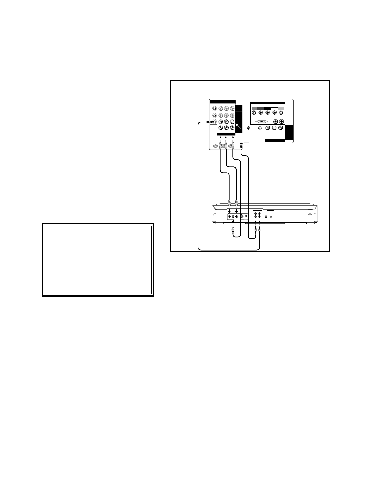
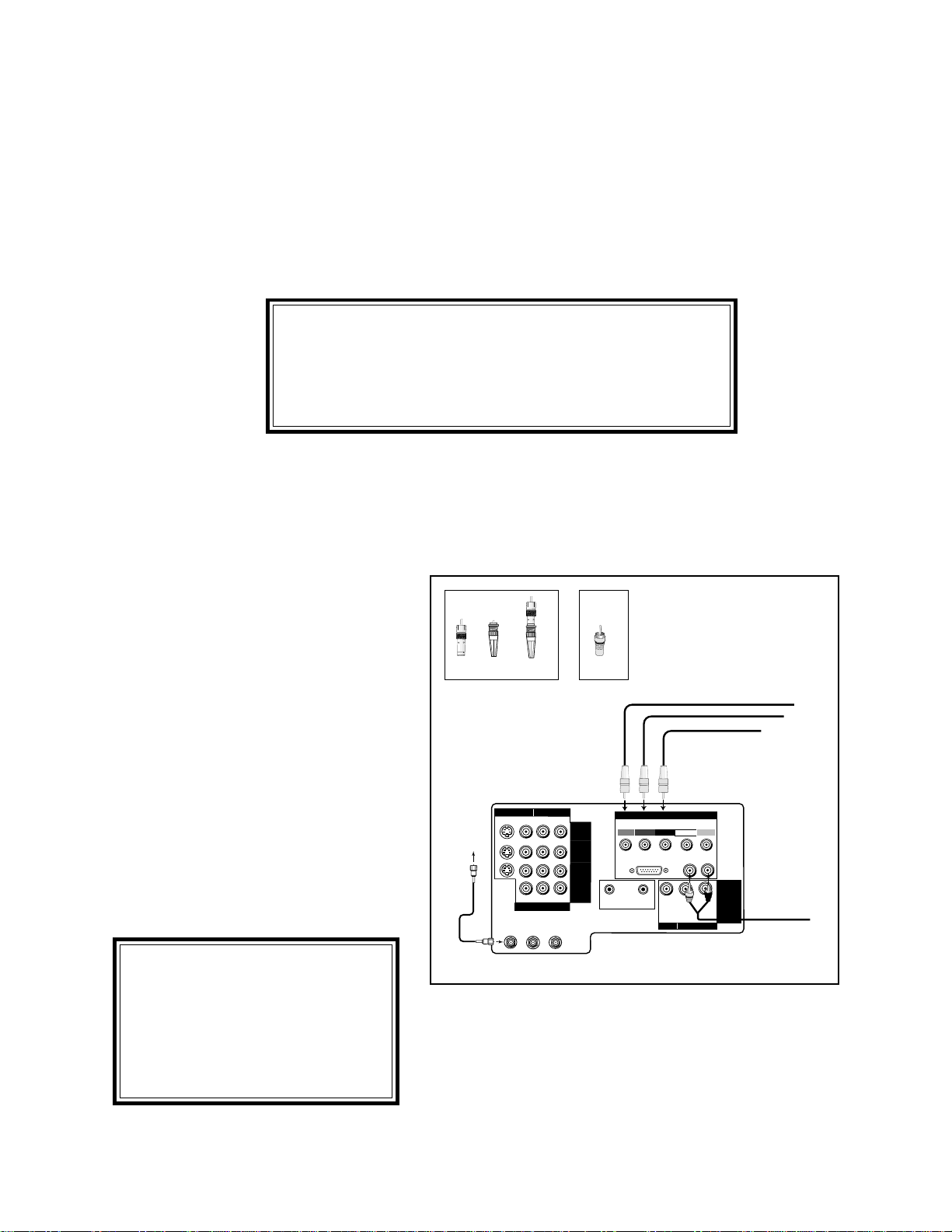
Connection of TV to DVD with Component Video Outputs
1. Connect the Component Video cables from
VIDEO OUT on the back of the DVD player
to DVD VIDEO input on the TV back panel,
matching the correct components:
• Y to Y,
• Cr to Cr,
• Cb to Cb.
2. Connect a set of audio cables from AUDIO
OUT on the back of the DVD player to
AUDIO, INPUT-3 on the TV back panel. The
red cable connects to the R (right) channel
and the white cable connects to the L (left)
channel.
R
L
ANALOG
VIDEO OUT
Y
Cb
Cr
1
2
AUDIO OUT
DVD back panel
TV back panel
ANT-B
LOOP
OUT
ANT-A
S-VIDEO V L
R
(MONO)
YCrCb
VIDEO AUDIO
INPUT-1
INPUT-2
INPUT-3
HDTV VIDEO
Y
Pr
H V
HDTV CONTROL
HDTV AUDIO
LR
(MONO)
VL
R
(MONO)
IR
HOME
THEATER
ACTIVE A/V
NETWORK
MONITOR
OUTPUT
VIDEO AUDIO
DVD VIDEO
HIGH-DEFINITION INTERFACE
Pb
IMPORTANT IMPORTANT
IMPORTANT IMPORTANT
IMPORTANT
IMPORTANT IMPORTANT
IMPORTANT IMPORTANT
IMPORTANT
1. See Appendix 4 for component
video signal compatibility
information.
2. For Digital Audio connections,
see the Owner's Guides of your
DVD Player and AV receiver.
15
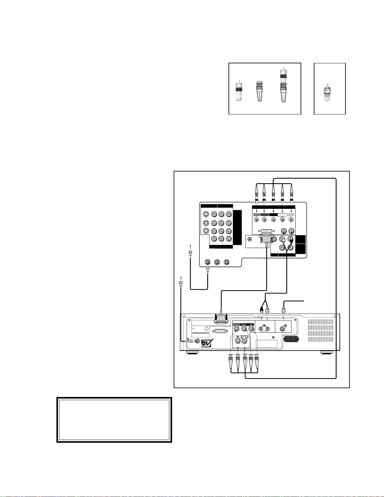
1. Connect the outside antenna to ANT
on the optional HD-1080 receiver.
2. Connect the incoming cable to ANT-A
on the television back panel.
3. Connect the HDTV cable to HDTV
CONTROL on the TV back panel and
the HDTV receiver back panel.
4. OPTIONAL: To use TV speakers,
connect the audio cables to HDTV
L(left) and R(right) AUDIO on the
HDTV receiver and the television back
panel.
5. Connect the color coded BNC cables
to HDTV VIDEO on the HDTV re-
ceiver. After fitting the BNC to RCA
adaptors onto the BNC cables, connect
them to the television back panel. The
sequence for connecting the color
cables is:
Y = green cable
Pr = red cable
Pb = blue cable
H = white cable
V = yellow cable
THIS PRODUCT CONTAINS ONE OR MORE PROGRAMS PROTECTED UNDER INTERNATIONAL AND U.S. COPYRIGHT LAWS AS
UNPUBLISHED WORKS. THEY ARE CONFIDENTIAL AND PROPRIETARY TO DOLBY LABORATORIES. THEIR REPRODUCTION OR
DISCLOSURE IN WHOLE OR IN PART, OR THE PRODUCTION OF DERIVATIVE WORKS THEREFROM WITHOUT THE EXPRESS PERMISSION
OF DOLBY LABORATIES IS PROHIBITED. COPYRIGHT 1982-1998 BY DOLBY LAORATORIES, INC. ALL RIGHTS RESERVED.
ANT
ATSC CERTIFIED
DIGITAL TELEVISION
TM
U
L
R
MITSUBISHI
HDTV RECEIVER
AC 120V 60 Hz 60 W
DISTRIBUTED BY MITSUBISHI CONSUMER
ELECTRONICS AMERICA, INC.
MODEL NO. HD-1080
HDTV CONTROL
6100 ATLANTIC BOULEVARD NORCROSS, GA 30071-1386
MADE IN JAPAN
LISTED
536Y
MANUFACTURED UNDER LICENSE FROM DOLBY LABORATORIES
R
G
B
HDTV VIDEO
HDTV AUDIO DIGITAL AUDIO OUT
H V
THIS DEVICE COMPLIES WITH PART 15 OF THE FCC RULES.
OPERATION IS SUBJECT TO THE FOLLOWING TWO
CONDITIONS; (1) THIS DEVICE MAY NOT CAUSE HARMFUL
INTERFERENCE, AND (2) THIS DEVICE MUSTACCEPT ANY
INTERFERENCE RECEIVED, INCLUDING INTERFERENCE
THAT MAY CAUSE UNDESIRED OPERATION.
AC LINE
ANT-B
LOOP
OUT
ANT-A
S-VIDEO V L
R
(MONO)
YCrCb
VIDEO AUDIO
INPUT-1
INPUT-2
INPUT-3
HDTV VIDEO
Y
Pr
H V
HDTV CONTROL
HDTV AUDIO
LR
(MONO)
VL
R
(MONO)
L
R
(MONO)
IR
HOME
THEATER
ACTIVE A/V
NETWORK
MONITOR
OUTPUT
PIP
AUDIO
OUTPUT
VIDEO AUDIO
DVD VIDEO
HIGH-DEFINITION INTERFACE
Pb
From the
Cable or
Cable Box
To Digital Audio Receiver
From the
Antenna
Connection of TV and Cable to Mitsubishi's HD-1080 Receiver
Connectors for TV and Cable to HDTV Receiver
The TV back panel has 5 RCA type connectors, for the HDTV
connection. The back panel of your HDTV receiver may use
RCA type connectors or BNC type connectors for its connec-
tion. If your HDTV receiver comes with BNC type connec-
tions, you will have to purchase BNC to RCA adaptors, to
connect the TV to the HDTV receiver. These adaptors should
be available at electronics supply stores.
BNC to
RCA BNC
Adaptor Connector
Adaptor
Fitted to
Connection
RCA
Connector
or
IMPORTANT IMPORTANT
IMPORTANT IMPORTANT
IMPORTANT
IMPORTANT IMPORTANT
IMPORTANT IMPORTANT
IMPORTANT
For Digital Audio connections, see
the Owner's Guides of your HDTV
receiver.
16
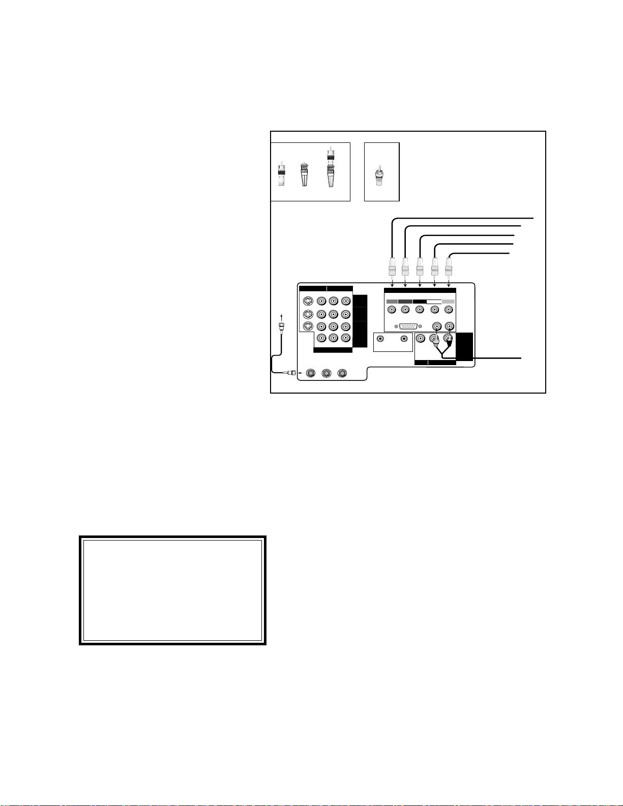
Connection of TV and Cable to HDTV Receiver with
Component Video Connections
ANT-B
LOOP
OUT
ANT-A
S-VIDEO V L
R
(MONO)
YCrCb
VIDEO AUDIO
INPUT-1
INPUT-2
INPUT-3
HDTV VIDEO
Y
Pr
H V
HDTV CONTROL
HDTV AUDIO
LR
(MONO)
VL
R
(MONO)
IR
HOME
THEATER
ACTIVE A/V
NETWORK
MONITOR
OUTPUT
VIDEO AUDIO
DVD VIDEO
HIGH-DEFINITION INTERFACE
Pb
From HDTV Receiver, Y Output
From HDTV Receiver, Pr Output
From HDTV Receiver, Pb Output
From the
Cable or
Cable Box
BNC to
RCA BNC
Adaptor Connector
Adaptor
Fitted to
Connection
RCA
Connector
or
From HDTV Receiver Audio
1. Connect the outside antenna to ANT on the
optional HDTV receiver.
2. Connect the incoming cable to ANT-A on
the television back panel.
3. Connect the RCA type cables or the fitted
RCA/BNC cables to Y, Pr and Pb on the
HDTV receiver.
4. Connect the RCA type cables or the fitted
RCA/BNC cables to Y, Pr, and Pb on the TV
back panel. You must also select the DTV
Assign Input setting (page 35) of YPrPb.
5. OPTIONAL: To use TV speakers, connect the
L(left) and R(right) audio cables to the op-
tional HDTV receiver and to HDTV AUDIO
on the television back panel.
Industry Standards for HDTV RGB signals systems, synchronizations and signal strengths have not
been established. These inputs will not be compatible with all HDTV receivers that offer RGB. If
your HDTV receiver offers both a HDTV component (Y, Pr, Pb) video system and a HDTV RGB
video signals, Mitsubishi suggests you use the HDTV component video system.
Connection of TV and Cable to HDTV Receiver
IMPORTANT IMPORTANT
IMPORTANT IMPORTANT
IMPORTANT
IMPORTANT IMPORTANT
IMPORTANT IMPORTANT
IMPORTANT
If a HD-1080 receiver was connected and you change to
another DTV receiver, you must turn the Power off, then
unplug and plug in the television to allow the new HD
receiver to work correctly.
IMPORTANT IMPORTANT
IMPORTANT IMPORTANT
IMPORTANT
IMPORTANT IMPORTANT
IMPORTANT IMPORTANT
IMPORTANT
1. See Appendix 4 for video signal
compatibility information.
2. For Digital Audio connections,
see the Owner's Guides of your
HDTV receiver and AV receiver.
17
Connection of TV and Cable to HDTV Receiver with
RGB Connections
ANT-B
LOOP
OUT
ANT-A
S-VIDEO V L
R
(MONO)
YCrCb
VIDEO AUDIO
INPUT-1
INPUT-2
INPUT-3
HDTV VIDEO
Y
Pr
H V
HDTV CONTROL
HDTV AUDIO
LR
(MONO)
VL
R
(MONO)
IR
HOME
THEATER
ACTIVE A/V
NETWORK
MONITOR
OUTPUT
VIDEO AUDIO
DVD VIDEO
HIGH-DEFINITION INTERFACE
Pb
From HDTV Receiver, Green Output
From HDTV Receiver, Red Output
From HDTV Receiver, Blue Output
From HDTV Receiver, Horizontal Sync
From HDTV Receiver, Vertical Sync
From the
Cable or
Cable Box
From HDTV Receiver Audio
BNC to
RCA BNC
Adaptor Connector
Adaptor
Fitted to
Connection
RCA
Connector
or
1. Connect the outside antenna to
ANT on the optional HDTV re-
ceiver.
2. Connect the incoming cable to ANT-
A on the television back panel.
3. Connect the RGB cables to the
HDTV receiver and the televesion
back panel. The sequence for
connecting the cables is:
HDTV Receiver TV Back
Panel
G (green) = Y
R (red) = Pr
B (blue) = Pb
If the receiver has separate sync*,
also connect:
H (
horizontal sync
) = H
V (vertical sync) = V
* do not connect if HDTV Receiver uses
"Sync on Green".
You must also select the DTV Assign
Input setting (page 35) of RGB.
4. OPTIONAL: To use TV speaker, connect
the L(left) and R(right) audio cables to
the optional HDTV receiver and to
HDTV AUDIO on the television back
panel.
IMPORTANT IMPORTANT
IMPORTANT IMPORTANT
IMPORTANT
IMPORTANT IMPORTANT
IMPORTANT IMPORTANT
IMPORTANT
1. See Appendix 4 for video signal
compatibility information.
2. For Digital Audio connections,
see the Owner's Guides of your
HDTV receiver and AV receiver.
18
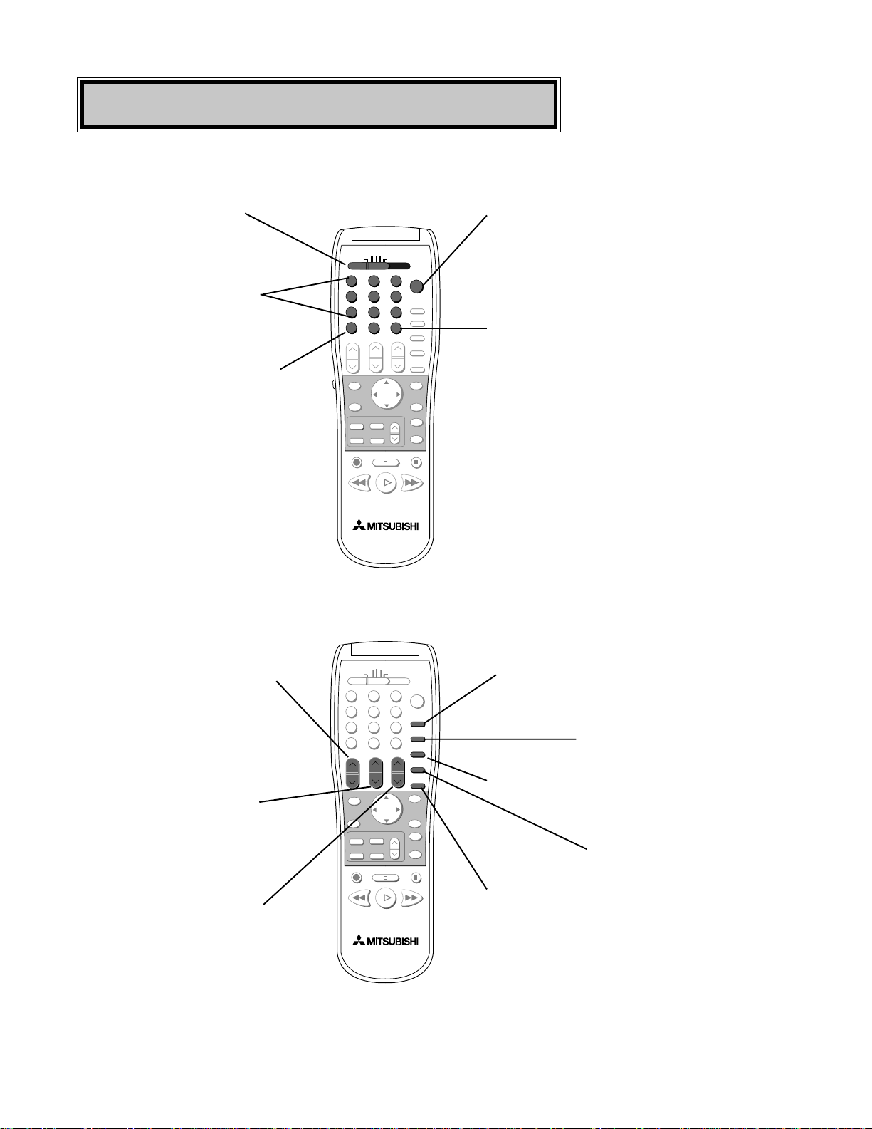
Remote Control Functions
1
2
3
5
6
789
0
SQV
QV
4
POWER
TV
AUDIO
CABLE/DBS/DTV
DVD
VCR
VOLUME
INPUT
SLEEP
VIDEO
AUDIO
MUTE
CHANNEL
SUB
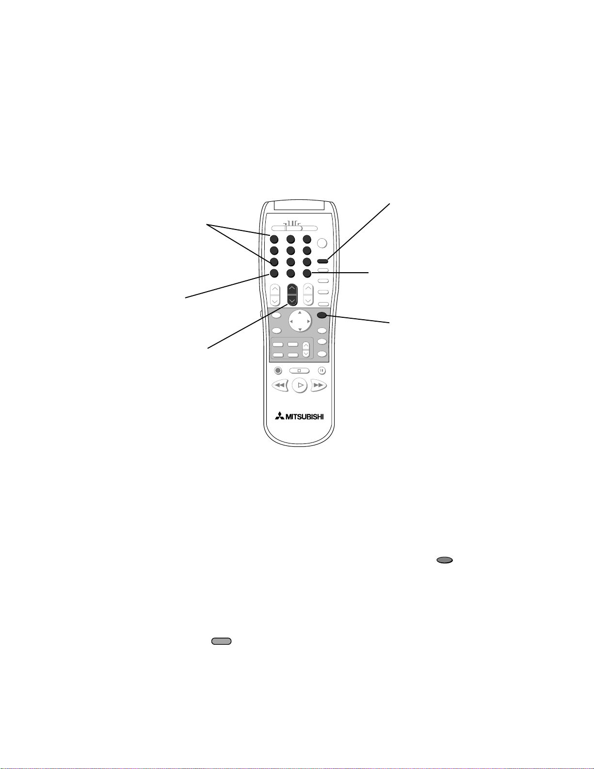
Select switch
Selects which A/V product
will be controlled by the
remote
Numbers
Individually select channels
or enter information into
TV
Power
Turns power on and off for the TV
or other A/V products
QV (QuickView
TM
)
Switches to last channel viewed
SQV (SuperQuickView
TM
)
Scan through a memorized list of
favorite channels
INPUT
Selects the signal you will watch
(Ant-A, Ant-B, DTV, Input-1,
Input-2, Input-3 [DVD component]
and Input-4)
CHANNEL
View channels in increasing
or decreasing numerical
order
VOLUME
Increases or decreases sound
SUB
When optional HD-1080 HDTV
receiver is connected, use to enter a
subchannel number
SLEEP
Sets the TV to turn off
within 2 hours
VIDEO
Individually selects the Video
settings
AUDIO
Individually selects the
Audio settings
MUTE
Turns on or off the sound
19
HOME
INFO
CANCEL
MENU
PIP/POP
FORMAT
PIP CH
ENTER
PIP INPUT
EXCH
GUIDE
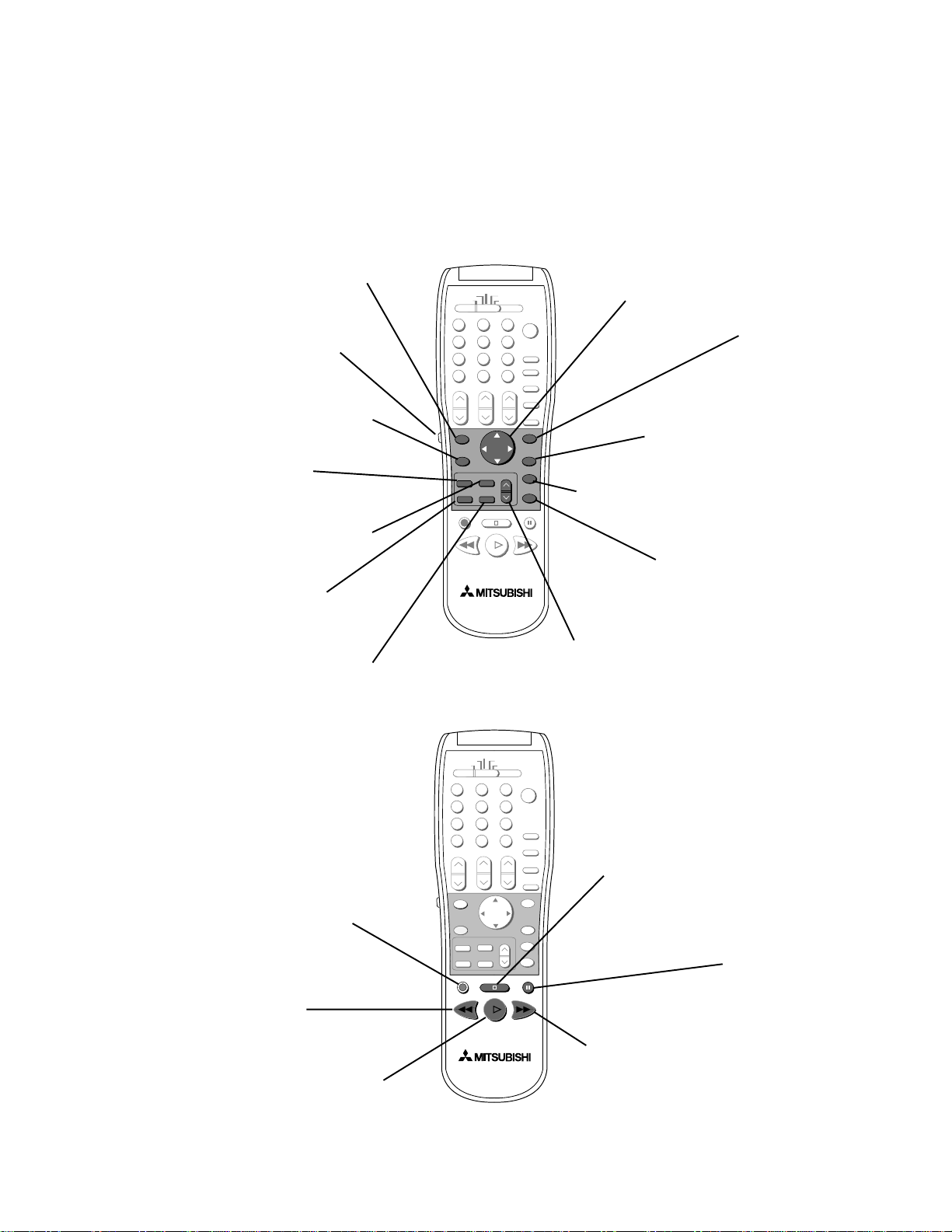
Remote Control Functions, continued
ENTER
Use after selecting a
channel number or
menu item
ADJUST
Selects menu items. Change
settings. Moves the PIP
on-screen location
CANCEL
Clear SQV and some
menu entries
MENU
Displays on-screen
menu choices
HOME
Exit on-screen menus and
return to TV viewing
INFO
Displays an on-screen
summary of current TV
settings and V-Chip program
ratings
PAUSE
REC
FF/FWDREW/REV
PLAY
STOP
REC
Manually record
programs on your VCR
STOP
To stop a VCR, DVD or
CD
REW/REV
Rewind and reverse search for the
VCR. Skip reverse for CD.
Reverse scan for DVD
PLAY
Plays a VCR, DVD or CD
PAUSE
Temporarily stops a
VCR, DVD or CD or
freezes the PIP/POP
FF/FWD
Fast forward or forward search for
a VCR. Skip forward for a CD. Fast
play for a DVD
GUIDE
When optional
HD-1080 HDTV
receiver is
connected, use to
display the DTV
Channel Guide
LIGHT
Press to light the white
buttons on the remote
control
FORMAT
Change the size and
shape of the main TV
picture
EXCH
Exchange PIP or POP
and main TV picture
PIP CH
Change the PIP channel, for
Ant-A, Ant-B or DTV (with
optional HD-1080 receiver)
PIP/POP
Use to display or
change PIP or POP
PIP INPUT
Use to select the PIP
or POP input source
20
IMPORTANT
IMPORTANT
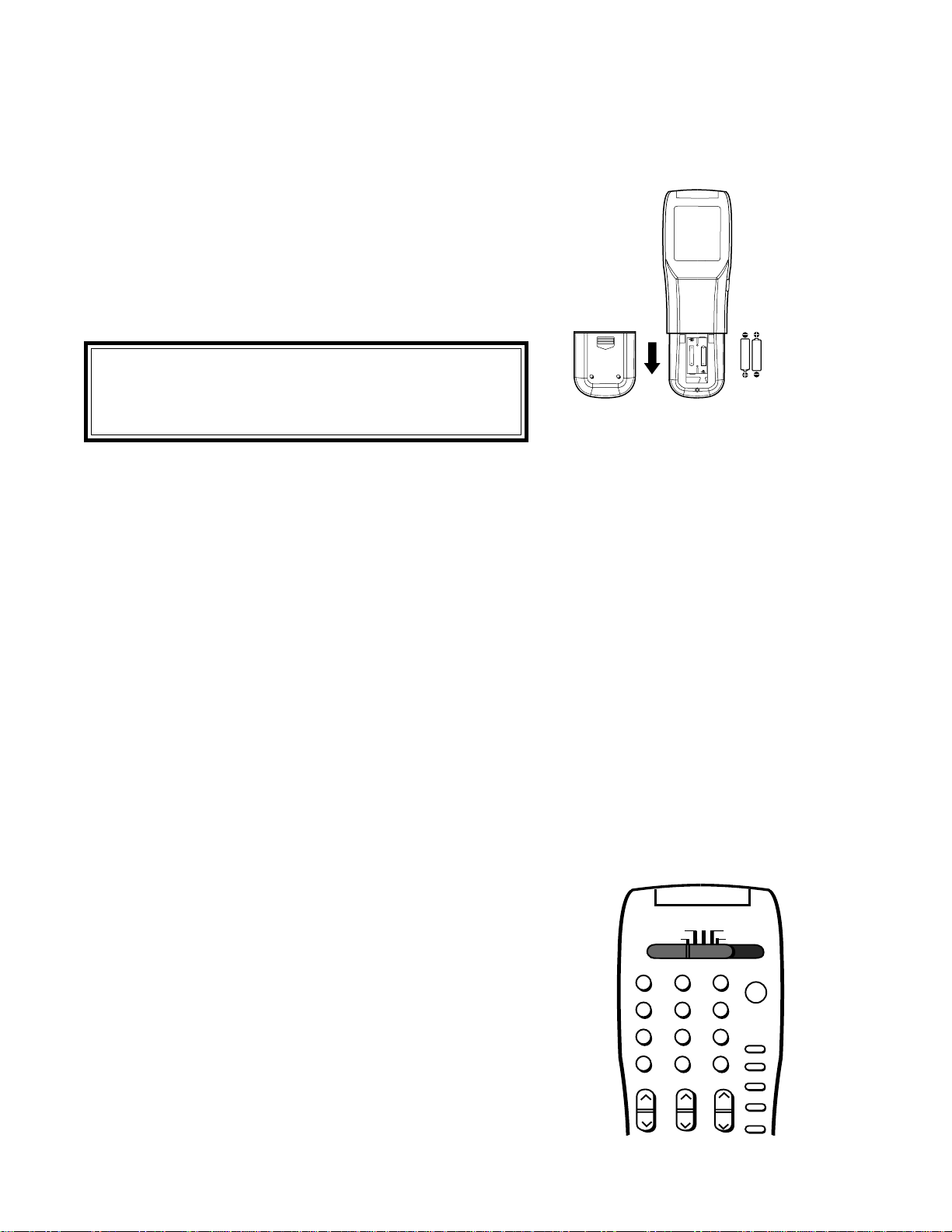
When you replace the batteries in your remote control,
the remote may return to its initial setting. You may
need to set up your remote again.
Operating Your Remote Control
size AAA
batteries
UM-4 AAA
RO3 1.5V
1. Remove the back cover of the remote control by pushing the
tab in the direction of the arrow and sliding off the cover.
2. Load the batteries, making sure the polarities(+) and (-) are correct.
Installing the batteries
For best results
• Be within 20 feet of the equipment when using the remote
control.
• Don’t press two or more buttons at the same time, unless you
are specifically instructed to do so in this owner’s guide.
• Don’t allow the remote control to get wet or become heated.
• Avoid dropping the remote control on a hard surface.
• When cleaning the remote control, don’t use any harsh chemi-
cals. Use only a soft, slightly moistened cloth.
• Don’t mix new batteries with old ones.
• Don’t heat, take apart, or throw batteries into a fire.
• Use AAA alkaline batteries.
TV
AUDIO
CABLE/DBS/DTV
DVD
VCR
Using the remote control with your TV
You can use your remote to control the TV, CABLE/DBS/
DTV, VCR, DVD or AUDIO. The remote has been preset
to operate the TV and other Mitsubishi products. It can be
set to control other brands of audio/video equipment.
To operate the TV, the select switch at the top of the
remote should be set to TV.
21
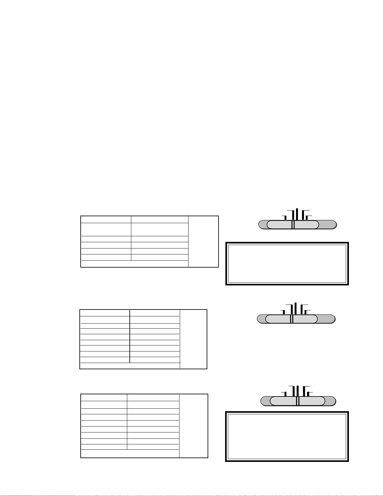
Remote Control of Other Audio and Video Products
• Move the slide switch at the top of the remote to select the
audio or video product you want to control.
• Press and hold the POWER button, so that it stays down when
you enter the code.
• Enter the code for the equipment from the appropriate list,
exactly as stated. If there is more than one code number, try the
numbers, until you find the correct code.. After setting the code,
release the POWER button.
• Point the remote at the equipment and press the POWER
button. If it is on and turns off or is off and turns on, the remote
will control the equipment. If not, try the next number.
Programming the Remote to Control Other Brands of
Audio and Video Products:
Satellite Receiver codes:
.
TV
AUDIO
CABLE/DBS/DTV
DVD
VCR
code to enter:
To reset to default code, enter 000
Satellite brand
Mitsubishi DTV - DBS
Dishnetwork
Hughes-DSS
RCA-DSS
Sony-DSS
Toshiba-DSS
Panasonic-DSS
Primestar
173
175
173
176
177
170
174
178
If your
satellite
code is not
listed here,
please see
page 79
for a
complete
listing.
TV
AUDIO
CABLE/DBS/DTV
DVD
VCR
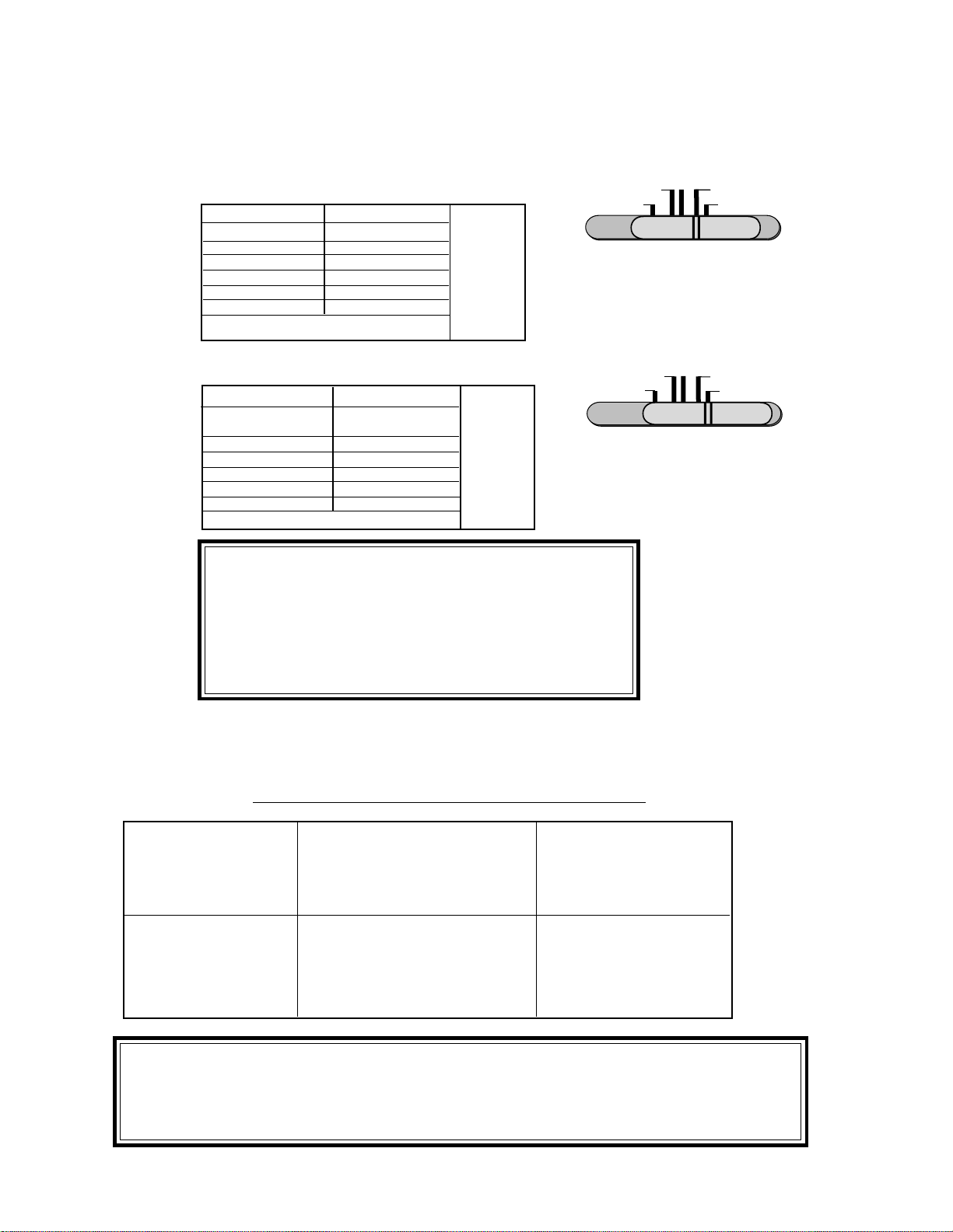
IMPORTANT
IMPORTANT
When set to TV, the PLAY, STOP,
REW/REV and the FF/FWD keys will
operate the VCR after the VCR codes
have been chosen.
code to enter:
To reset to default code, enter 000
VCR brand
Mitsubishi
Hitachi
JVC
Philips/Magnavox
Panasonic
RCA
Sony
Toshiba
001, 002
020, 043, 065
030, 054, 059
043, 044, 051
041, 042, 043
020, 053, 065
048, 049, 050
021, 066
If your
VCR
code is not
listed here,
please see
page 80
for a
complete
listing.
VCR codes:
code to enter:
To reset to default code, enter 000
Cable box brand
General Instruments/
Jerrold
Oak
Pioneer
Scientific Atlanta
Zenith
111, 119, 120, 121, 122,
123, 124, 125, 126, 127
102, 137, 139
If your
cable box
code is not
listed here,
please see
page 79
for a
complete
listing.
101, 116
111,112,113
100, 117
TV
AUDIO
CABLE/DBS/DTV
DVD
VCR
IMPORTANT
IMPORTANT
If you cannot turn the cable box ON
by pressing POWER, try pressing the
CHANNEL or the number buttons.
Cable Box codes:
22
Remote Control of Other Audio and Video Product, continued
DVD Player codes:
TV AUDIO
CABLE/DBS/DTV
DVD
VCR
code to enter:
To reset to default code, enter 000
DVD/LDP brand
Mitsubishi (DVD)
Mitsubishi (LDP)
Panasonic
Pioneer DVD (LDP)
Sony
Toshiba
003
016, 017
250
252 (016, 017)
254
253
If your
DVD code
is not
listed here,
please see
page 79
for a
complete
listing.
AV Receiver codes:
TV
AUDIO
CABLE/DBS/DTV
DVD
VCR
code to enter:
To reset to default code, enter 000
Audio brand
Mitsubishi AV receiver
with CD player
Kenwood
Onkyo
Pioneer
Sony
Yamaha
010, 011
200, 208
209, 214
205, 207
222
201, 202
If your
Audio
code is not
listed here,
please see
page 79
for a
complete
listing.
IMPORTANT
IMPORTANT
If the slide switch is set to TV when you enter an AV re-
ceiver code, VOLUME and MUTE will control by the AV
receiver, rather than the TV. To return volume and mute
control to the TV, set the slide switch to TV, press and
hold POWER and enter 000.
IMPORTANT
IMPORTANT
Some manufacturers may change their products, or they may use more than one remote
control system. If this is the case, your remote may not be able to operate your VCR, DVD
Player, Cable Box, Satellite Receiver or AV Receiver.
Additional slide switch feature: -for multiple A/V component systems
After selecting the correct codes, you can use the slide switch to control more than one type of
A/V product. The possible equipment that can be set up for each switch position is shown in the
following table.
Only one device is allowed for each slide switch position.
TV position: Cable/DBS position: DVD position:
• TV • cable box or • any listed DVD or
• any A/V receiver • satellite receiver • any listed VCR or
(volume, mute only) • any listed cable box
VCR position: Audio position:
• any listed VCR or • any listed AV receiver or
• Mitsubishi DVD or • Mitsubishi CD player or
player • any listed cable box
23
* Using the Number buttons:
For non-DTV channels:
When changing channels directly, you can change them faster by:
1. entering three numbers; for channel 2, press 002
2. press number and ENTER; for channel 2, press 2 then .
For DTV channels when an optional HD-1080 receiver is con-
nected:
1. Use the number buttons to select the one or two digit major channel.
2. Press .
3.
Use the number buttons to select the one or two digit minor channel
(if available).
Two asterisks will display if no minor channel exists: 17.**
Two question marks will display while TV is looking for minor channel: 12.??
1
2
3
5
6
789
0
SQV
QV
4
SUB
CHANNEL
GUIDE
Changing Channels
Remote Control Channel Selection
There are several ways to select channels with the remote control:
OR
ENTER
Numbers*
enter the number, the
channel will change
in 4 seconds, or
after the third number
Channel
press to view channels in
order, including DTV
channels (when optional
HD-1080 receiver is
connected)
SQV (SuperQuickView
TM
)
press to see stored
SQV channels, in order
QV (Quick View
TM
)
press QV to see the last
channel selected
SUB
When optional HD-1080
receiver is connected, use
after choosing a major DTV
channel, to enter minor (sub)
channel
SUB
GUIDE
Displays DTV Channel Guide
(when optional HD-1080
receiver is connected)
24
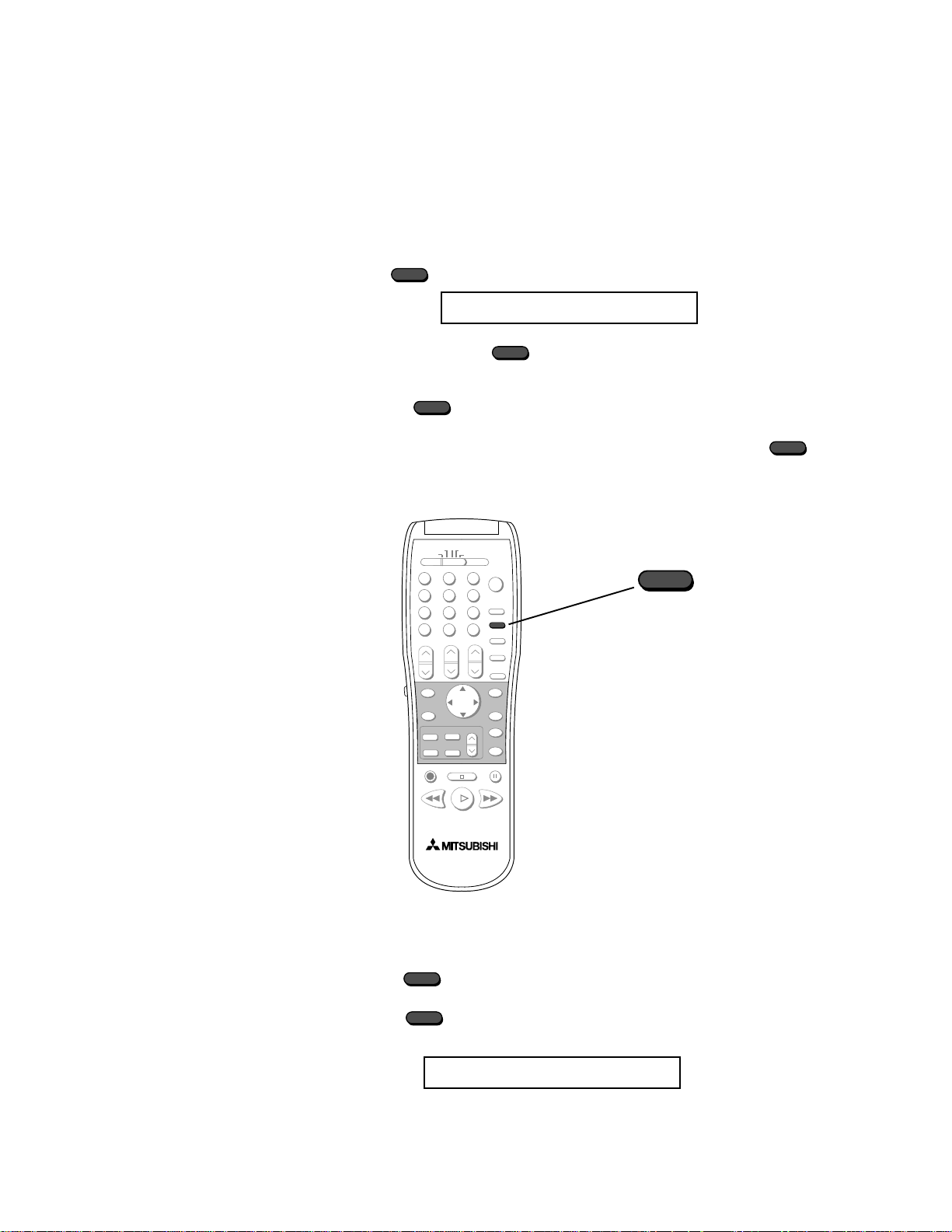
Remote Control of the Sleep Timer
Setting the Sleep Timer
Sleep: 030 Min.
With each press of the time increases in 30 minute intervals
until the maximum of 120 minutes is displayed.
Release when the desired time is set.
To see how much time is left until the timer goes off, press
once. The remaining time will display on-screen.
Canceling the Sleep Timer
Press to see the on-screen display.
Press until you see the message:
The timer will be canceled.
SLEEP
Press on the remote control. The TV will display the message:
Sleep: OFF
SLEEP
SLEEP
SLEEP
SLEEP
SLEEP
SLEEP
SLEEP
25
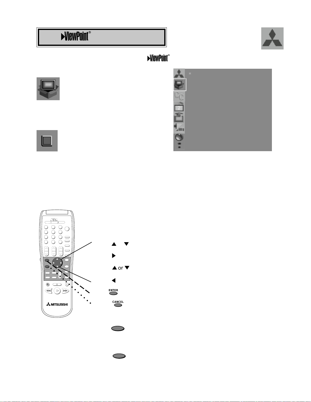
The ViewPoint system includes the following special features:
• The currently selected icon or button is highlighted with a yellow
outline and the text color will be yellow.
• On-screen instructions provide complete menu choice information.
• Some on-screen menu options must be set before other options are
available. For example, “Set the Timer” will only be possible if “Clock
Time” and “Set Day” have been set.
Making Selections:
ADJUST to select the menu item you want to change
ADJUST to move to the setting field
ADJUST to change the settings
ADJUST to move back to the menu item
ENTER to select an option, or start an automatic function
CANCEL to clear a setting, or stop an automatic function
To exit the on-screen menus:
Press the MENU key to move back one menu screen at a time until
you exit all the menus to return to television viewing
OR
Press HOME to exit all menus with one keystroke and return to
television viewing
The Menu System
HOME
MENU
or
CANCEL
ENTER
Your television has Mitsubishi’s exclusive
on screen operating system, which provides on-
screen information for menu choices and changes.
○○○○○○○○○○○○○○
ENTER
CANCEL
or
MAIN MENU
CAPTIONS
CHANNEL EDIT
ADVANCED FEATURES
AUDIO/VIDEO SETTINGS
ADJUST to select item
SETUP
ENTER for menu or to start
MENU to return
A picture (icon) will be highlighted when selected
with the ADJUST arrows. The picture (icon)
indicates that a submenu or automatic function can
be changed. Press the ENTER button to display
the options or start the function.
A square button indicates that you make
changes to this menu choice.
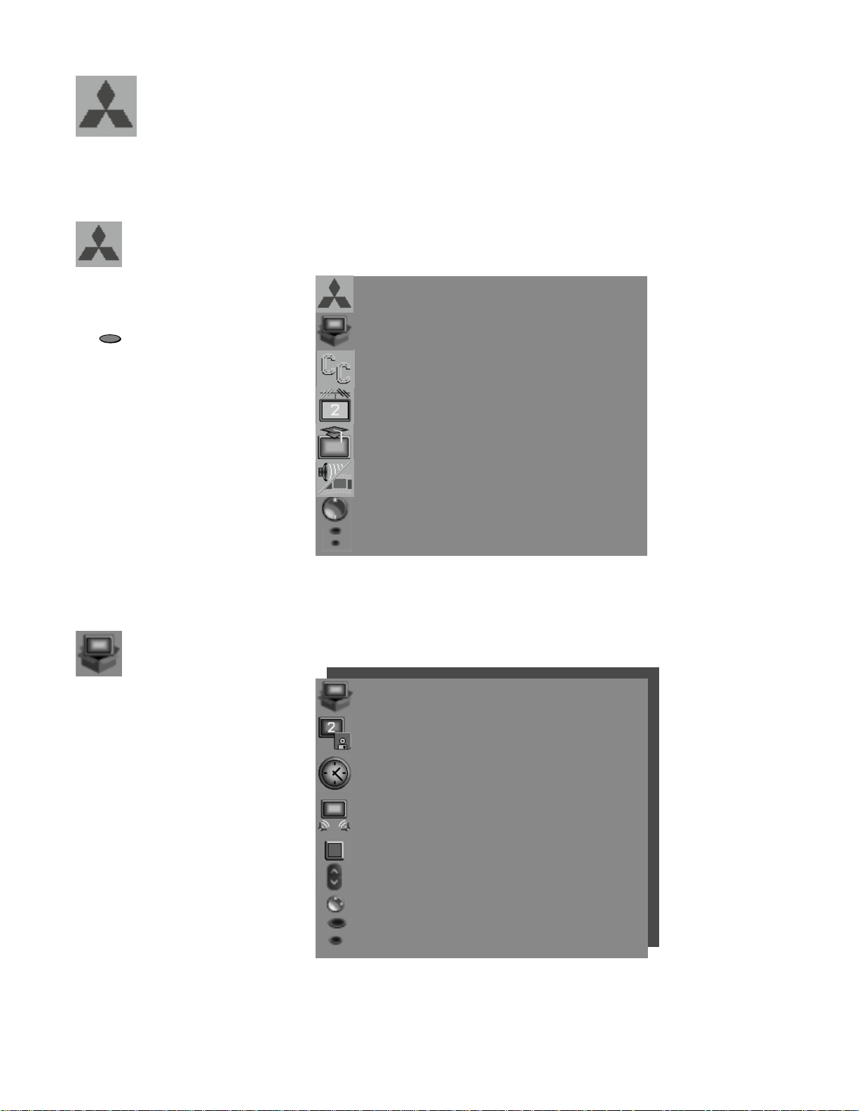
26
The Main Menu Screen will
always be the first screen that
appears when you press the
button.
MAIN MENU
CAPTIONS
CHANNEL EDIT
ADVANCED FEATURES
AUDIO/VIDEO SETTINGS
ADJUST to select item
SETUP
ENTER for menu or to start
MENU to return
MAIN
Menu
Basic set up instructions and
procedures are available
through the SETUP menu
screens. You can put channels
in memory, set the time and
day, set your TV to be part of
a Home Theater setup, view
the menus in English or
Spanish, and turn on or off
inputs connected to the
television.
SETUP
Menu
SETUP menu
MEMORIZE CHANNELS :Ant-A
Cable
CLOCK
AV CONNECTION
(Home Theater)
Language :English
(Idioma)
ASSIGN INPUT
ADJUST to select item then
move to and change option.
ENTER for menu or to start
MENU to return
MAIN MENU
Menu Screens
MENU
27
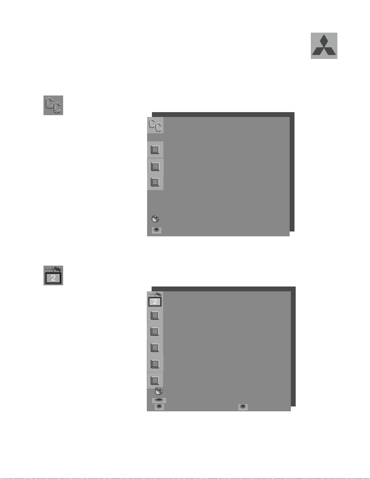
Use to customize channel
information for Ant-A, Ant-B,
and DTV (if optional HD-
1080 receiver is connected).
Manually add or delete
channels from memory, name
channels for Ant-A and Ant-B,
or add your favorite channels
to a SQV
(SuperQuickView
TM
) list.
Display captions or text,
choose black or gray as the
background color for the
closed caption area, enable
the DTV channel guide (when
optional HDTV-1080 receiver
CHANNEL
EDIT Menu
Menu Screens, continued
CAPTIONS menu
Closed Captions :On if
mute
CC Background :Gray
DTV Channel Guide :On
ADJUST to select item then
move to and change option
MENU to return
MAIN MENU
CAPTIONS
Menu
CHANNEL EDIT menu
Antenna :DTV
Channel :02.02
Memory :Added
Major chan. only
Name :N/A
Can not name DTV
SQV :SQV1
Off
ADJUST to select item then
move to and change option
ENTER for menu or to start
MENU to return CANCEL
MAIN MENU
 Loading...