


 Loading...
MITSUBISHI
Mitsubishi Industrial Robot
RV-6S Series INSTRUCTION MANUAL
ROBOT ARM SETUP & MAINTENANCE
 BFP-A8323-A
Supplemental Instruction
Thank you for purchasing the Mitsubishi Industrial Robot MELFA Series.
This document additionally explains to the Mitsubishi Industrial Robot "RV-6S Series INSTRUVTION MANUAL (BFP-A8323)".
Therefore, check the content, and use it together with your instruction manual.
1. Outline
When lubricating, removal of the drain bolt or the plug is unnecessary.
The robot which is the target of these supplementary contents is shown below.
No. |
Target products |
|
1 |
Produced in September, |
|
2006 and afterwards. |
||
|
||
2 |
Produced before August, |
|
2006. |
||
|
The discrimination method
The DATE columns of the rated plate of the robot arm are all the robots after '2006-09'.
The robot by which the blue round sticker is stuck on the rated plate of the robot arm.
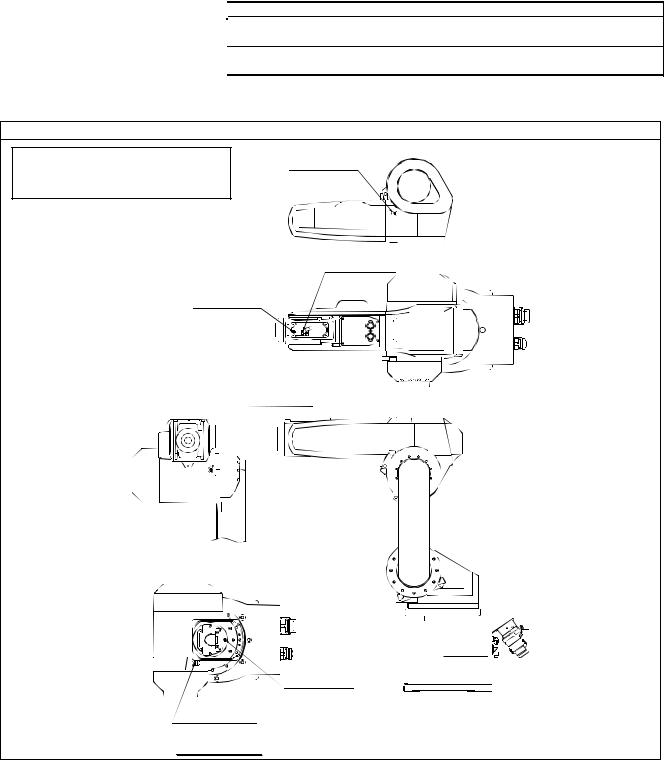
2. Correction of the lubrication port
Revision place
P5-49 “Fig.5-6 Lubrication positions”
4. J4 axis
*The drain bolt or the plug of lubrication port all the axes were erased.
5. J5 axis lubrication port
6. J6 axis lubrication port
3. J3 axis lubrication port


 A
A
 1. J1 axis lubrication port
2. J2 axis lubrication port
View
BFP-A8323-A01-A

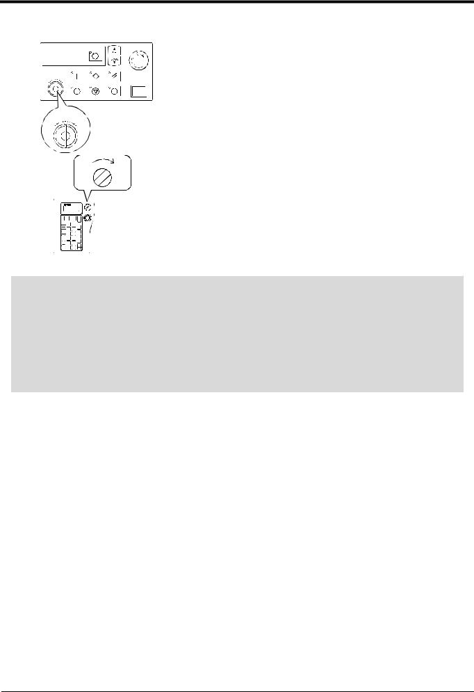
3.Change of the lubrication method and notes
Details of change and supplement
A procedure and precautions applicable to the products affected by the change were added to “(2) Lubrication method” on P5-50. The procedure applicable to the products affected by the change is described below. When lubricating all other products, follow the original procedure specified in the instruction manual.
(1)Lubrication method of products affected by the change
1)Set the robot to the posture shown in Fig. 5-6.
2)Refer to the "5.3.2Installing/removing the cover" on page 44 and remove the covers.
3)Insert the grease shown in Table 5-5 using a grease gun of manual type from the lubrication grease nipple.
4)Replace the covers with the removal procedure in reverse.
(2)Precautions for lubrication
Take note of the following points when lubricating all products, regardless of whether or not they are affected by the change.
CAUTION |
Use manual grease gun, and inject grease with pressure 0.03Mpa or less. Do not |
use the grease gun, which derived by the factory air presser to |
|
|
avoid injecting by too high pressure. |
BFP-A8323-A01-A
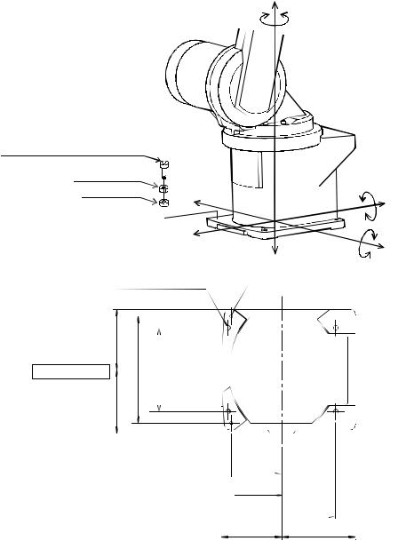
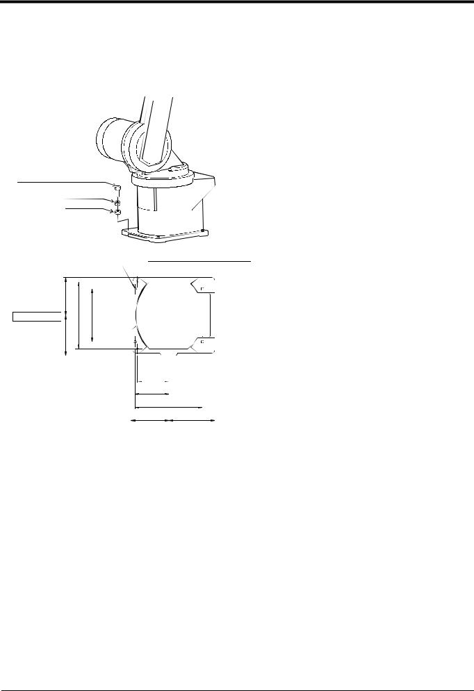
4. Supplemental note for the installation surface receiving force
Supplemental details
Magnitude of each reaction force added to P2-8 “2.2.3 Installation procedures”.
Table 2-2 shows the maximum reaction force (design values) that may be applied to an installation stand. Please use these values as reference when designing the installation stand.
4-M8×40 hexagon socket bolt (Four positions)
Spring washer |
|
|
||
Plain washer |
|
|
||
|
|
|
||
|
|
|
||
|
|
|
|
|
|
|
|
|
|
|
|
|
|
|
4-φ9 installation hole |
2-φ6 holes |
|||
(prepared holes for φ8 positioning pins) |
||||
|
|
|
||
115 |
|
|
|
|
Robot front |
|
|
|
|
122 |
204 |
160 |
|
|
6.3a (Installation)
6.3a (Installation)


96 |
|
102.5 |
|
|
205 |
115 |
140 |
Base bottom
Fig.2-3 Installation dimensions
Table 2-2 Magnitude of each reaction force
Item |
Unit |
Value |
Tilt moment : ML |
N m |
892 |
Torsional moment : MT |
N m |
892 |
Horizontal direction translation force : FH |
N |
800 |
Vertical direction translation force : FV |
N |
1,400 |
BFP-A8323-A01-A

 Safety Precautions
Always read the following precautions and the separate "Safety Manual" before starting use of the robot to learn the required measures to be taken.
|
|
CAUTION |
All teaching work must be carried out by an operator who has received special training. |
|
|||
|
|
||
|
|
|
(This also applies to maintenance work with the power source turned ON.) |
|
|
|
→ Enforcement of safety training |


 CAUTION


 WARNING


 CAUTION


 WARNING
For teaching work, prepare a work plan related to the methods and procedures of oper- ating the robot, and to the measures to be taken when an error occurs or when restart- ing. Carry out work following this plan. (This also applies to maintenance work with the power source turned ON.)
→ Preparation of work plan
Prepare a device that allows operation to be stopped immediately during teaching work. (This also applies to maintenance work with the power source turned ON.)
→ Setting of emergency stop switch
During teaching work, place a sign indicating that teaching work is in progress on the start switch, etc. (This also applies to maintenance work with the power source turned ON.)
→ Indication of teaching work in progress
Provide a fence or enclosure during operation to prevent contact of the operator and robot.
→ Installation of safety fence


 CAUTION


 CAUTION


 CAUTION
Establish a set signaling method to the related operators for starting work, and follow this method.
→ Signaling of operation start
As a principle turn the power OFF during maintenance work. Place a sign indicating that maintenance work is in progress on the start switch, etc.
→ Indication of maintenance work in progress
Before starting work, inspect the robot, emergency stop switch and other related devices, etc., and confirm that there are no errors.
→ Inspection before starting work

The points of the precautions given in the separate "Safety Manual" are given below. Refer to the actual "Safety Manual" for details.
|
|
CAUTION |
Use the robot within the environment given in the specifications. Failure to do so could |
|
|||
|
|
||
|
|
|
lead to a drop or reliability or faults. (Temperature, humidity, atmosphere, noise environ- |
|
|
|
ment, etc.) |


 CAUTION


 CAUTION


 CAUTION


 CAUTION


 CAUTION


 WARNING


 WARNING


 CAUTION


 WARNING
Transport the robot with the designated transportation posture. Transporting the robot in a non-designated posture could lead to personal injuries or faults from dropping.
Always use the robot installed on a secure table. Use in an instable posture could lead to positional deviation and vibration.
Wire the cable as far away from noise sources as possible. If placed near a noise source, positional deviation or malfunction could occur.
Do not apply excessive force on the connector or excessively bend the cable. Failure to observe this could lead to contact defects or wire breakage.
Make sure that the workpiece weight, including the hand, does not exceed the rated load or tolerable torque. Exceeding these values could lead to alarms or faults.
Securely install the hand and tool, and securely grasp the workpiece. Failure to observe this could lead to personal injuries or damage if the object comes off or flies off during operation.
Securely ground the robot and controller. Failure to observe this could lead to malfunc- tioning by noise or to electric shock accidents.
Indicate the operation state during robot operation. Failure to indicate the state could lead to operators approaching the robot or to incorrect operation.
When carrying out teaching work in the robot's movement range, always secure the pri- ority right for the robot control. Failure to observe this could lead to personal injuries or damage if the robot is started with external commands.


 CAUTION


 CAUTION
Keep the jog speed as low as possible, and always watch the robot. Failure to do so could lead to interference with the workpiece or peripheral devices.
After editing the program, always confirm the operation with step operation before starting automatic operation. Failure to do so could lead to interference with peripheral devices because of programming mistakes, etc.


 CAUTION


 CAUTION


 WARNING


 CAUTION
Make sure that if the safety fence entrance door is opened during automatic operation, the door is locked or that the robot will automatically stop. Failure to do so could lead to personal injuries.
Never carry out modifications based on personal judgments, or use non-designated maintenance parts.
Failure to observe this could lead to faults or failures.
When the robot arm has to be moved by hand from an external area, do not place hands or fingers in the openings. Failure to observe this could lead to hands or fingers catching depending on the posture.
Do not stop the robot or apply emergency stop by turning the robot controller's main power OFF. If the robot controller main power is turned OFF during automatic operation, the robot accuracy could be adversely affected.Moreover, it may interfere with the peripheral device by drop or move by inertia of the arm.
|
|
CAUTION |
Do not turn off the main power to the robot controller while rewriting the internal |
|
|||
|
|
||
|
|
|
information of the robot controller such as the program or parameters. |
|
|
|
If the main power to the robot controller is turned off while in automatic operation or |
|
|
|
rewriting the program or parameters, the internal information of the robot controller may |
|
|
|
be damaged. |
Revision history
Date of Point |
Instruction Manual No. |
Revision Details |
|
|
|
|
|
|
2003-10-10 |
BFP-A8323 |
First print |
|
|
|
2004-05-20 |
BFP-A8323-A |
Installing the hand input/output cable was added. |
|
|
Error in writing correction. |
|
|
|
|
|
|

■ Introduction
Thank you for purchasing the Mitsubishi industrial robot.
This instruction manual explains procedures to be taken for unpacking, installing, servicing and inspecting the robot arm.
Always read through this manual before starting use to ensure correct usage of the robot.
No part of this manual may be reproduced by any means or in any form, without prior consent from Mitsubishi.
The details of this manual are subject to change without notice.
An effort has been made to make full descriptions in this manual. However, if any discrepancies or unclear points are found, please contact your dealer.
The information contained in this document has been written to be accurate as much as possible. Please interpret that items not described in this document "cannot be performed.".
Please contact your nearest dealer if you find any doubtful, wrong or skipped point.
Copyright(C) 2003 MITSUBISHI ELECTRIC CORPORATION
|
|
CONTENTS |
|
|
|
|
Page |
1 Before starting use ......................................................................................................................................................................... |
1-1 |
||
1.1 |
Using the instruction manuals ............................................................................................................................................ |
1-1 |
|
1.1.1 The details of each instruction manuals ................................................................................................................ |
1-1 |
||
1.1.2 Symbols used in instruction manual ........................................................................................................................ |
1-2 |
||
1.2 |
Safety Precautions ................................................................................................................................................................. |
1-3 |
|
1.2.1 Precautions given in the separate Safety Manual ............................................................................................. |
1-4 |
||
2 Unpacking to Installation .............................................................................................................................................................. |
2-5 |
||
2.1 |
Confirming the product ......................................................................................................................................................... |
2-5 |
|
2.2 |
Installation .................................................................................................................................................................................. |
2-6 |
|
2.2.1 Unpacking ............................................................................................................................................................................ |
2-6 |
||
2.2.2 Transportation procedures (Transporting with a crane) ................................................................................. |
2-7 |
||
2.2.3 Installation procedures .................................................................................................................................................. |
2-8 |
||
2.2.4 Grounding procedures .................................................................................................................................................... |
2-9 |
||
|
(1) |
Grounding methods ..................................................................................................................................................... |
2-9 |
|
(2) |
Grounding procedures ............................................................................................................................................... |
2-9 |
2.2.5 Connecting with the controller ................................................................................................................................ |
2-10 |
||
2.3 |
Setting the origin ................................................................................................................................................................... |
2-12 |
|
2.3.1 Installing the teaching pendant (T/B) ................................................................................................................... |
2-12 |
||
|
(1) |
Installing with the control power OFF .............................................................................................................. |
2-12 |
2.3.2 Setting the origin with the origin data input method ...................................................................................... |
2-13 |
||
|
(1) |
Confirming the origin data ..................................................................................................................................... |
2-13 |
|
(2) |
Turning ON the control power ............................................................................................................................. |
2-13 |
|
(3) |
Preparing the T/B ..................................................................................................................................................... |
2-14 |
|
(4) |
Selecting the origin setting method ................................................................................................................... |
2-15 |
|
(5) |
Inputting the origin data ......................................................................................................................................... |
2-16 |
|
(6) |
Installing the shoulder coverB ............................................................................................................................. |
2-17 |
2.4 |
Confirming the operation .................................................................................................................................................... |
2-18 |
|
|
(1) |
JOINT jog operation ................................................................................................................................................. |
2-21 |
|
(2) |
XYZ jog operation ...................................................................................................................................................... |
2-23 |
|
(3) |
TOOL jog operation .................................................................................................................................................. |
2-25 |
|
(4) |
3-axis XYZ jog operation ....................................................................................................................................... |
2-27 |
|
(5) |
CYLNDER jog operation ......................................................................................................................................... |
2-29 |
3 Installing the option devices ..................................................................................................................................................... |
3-31 |
||
3.1 |
Installing the solenoid valve set (1S-VD01-02/VD02-02/VD03-02/VD04-02) ........................................ |
3-31 |
|
3.2 |
Installing the hand input cable ......................................................................................................................................... |
3-34 |
|
3.3 |
Installing the hand output cable ...................................................................................................................................... |
3-35 |
|
3.4 |
.Changing the operating range ......................................................................................................................................... |
3-36 |
|
4 Basic operations ............................................................................................................................................................................ |
4-38 |
||
5 Maintenance and Inspection ..................................................................................................................................................... |
5-39 |
||
5.1 |
Maintenance and inspection interval ............................................................................................................................. |
5-39 |
|
5.2 |
Inspection items ..................................................................................................................................................................... |
5-40 |
|
5.2.1 Daily inspection items .................................................................................................................................................. |
5-40 |
||
5.2.2 Periodic inspection ........................................................................................................................................................ |
5-41 |
||
5.3 |
Maintenance and inspection procedures ..................................................................................................................... |
5-42 |
|
5.3.1 Robot arm structure ..................................................................................................................................................... |
5-42 |
||
5.3.2 Installing/removing the cover ................................................................................................................................... |
5-44 |
||
5.3.3 Inspection, maintenance and replacement of timing belt .............................................................................. |
5-46 |
||
|
(1) |
Timing belt replacement period ......................................................................................................................... |
5-46 |
|
(2) |
Inspection, maintenance and replacement of J5-axis timing belt ........................................................ |
5-47 |
|
(3) |
Timing belt tension ................................................................................................................................................... |
5-48 |
5.3.4 Lubrication ........................................................................................................................................................................ |
5-49 |
||
|
(1) |
Lubrication position and specifications ............................................................................................................ |
5-49 |
i
|
|
|
Page |
(2) |
Lubrication method ................................................................................................................................................... |
5-50 |
|
5.3.5 Replacing the backup battery ................................................................................................................................... |
5-51 |
||
(1) |
Replacing the robot arm battery ......................................................................................................................... |
5-51 |
|
5.4 Maintenance parts ................................................................................................................................................................. |
5-52 |
||
5.5 Resetting the origin .............................................................................................................................................................. |
5-53 |
||
5.5.1 Jig method ........................................................................................................................................................................ |
5-54 |
||
(1) |
J1 |
axis origin setting ................................................................................................................................................ |
5-55 |
(2) |
J2 |
axis origin setting ................................................................................................................................................ |
5-56 |
(3) |
J3 |
axis origin setting ................................................................................................................................................ |
5-57 |
(4) |
J4 |
axis origin setting ................................................................................................................................................ |
5-58 |
(5) |
J5 |
axis origin setting ................................................................................................................................................ |
5-59 |
(6) |
J6 |
axis origin setting ................................................................................................................................................ |
5-60 |
5.5.2 User origin method ........................................................................................................................................................ |
5-61 |
||
5.5.3 ABS origin method ........................................................................................................................................................ |
5-63 |
||
5.5.4 Recording the origin data ........................................................................................................................................... |
5-65 |
||
(1) |
Confirming the origin data label ........................................................................................................................... |
5-65 |
|
(2) |
Confirming the origin data ..................................................................................................................................... |
5-65 |
|
(3) |
Recording the origin data ....................................................................................................................................... |
5-65 |
|
(4) |
Installing the cover ................................................................................................................................................... |
5-65 |
|
6Appendix............................................................................................................................................................................... |
|
|
Appendix-66 |
Appendix 1 |
Configuration flag ............................................................................................................................ |
Appendix-66 |
|
ii
1Before starting use
1 Before starting use
This chapter explains the details and usage methods of the instruction manuals, the basic terminology and the safety precautions.
1.1 Using the instruction manuals
1.1.1 The details of each instruction manuals
The contents and purposes of the documents enclosed with this product are shown below. Use these documents according to the application.
For special specifications, a separate instruction manual describing the special section may be enclosed.
Safety Manual
Explains the common precautions and safety measures to be taken for robot handling, system design and manufacture to ensure safety of the operators involved with the robot.
Standard
Specifications
Robot Arm
Setup &
Maintenance
Controller
Setup, Basic
Operation and
Maintenance
Detailed
Explanation of
Functions and
Operations
Troubleshooting
Explains the product's standard specifications, factory-set special specifications, option configuration and maintenance parts, etc. Precautions for safety and technology, when incorporating the robot, are also explained.
Explains the procedures required to operate the robot arm (unpacking, transportation, installation, confirmation of operation), and the maintenance and inspection procedures.
Explains the procedures required to operate the controller (unpacking, transportation, installation, confirmation of operation), basic operation from creating the program to automatic operation, and the maintenance and inspection procedures.
Explains details on the functions and operations such as each function and operation, commands used in the program, connection with the external input/output device, and parameters, etc.
Explains the causes and remedies to be taken when an error occurs. Explanations are given for each error No.
Using the instruction manuals 1-1

1Before starting use
1.1.2 Symbols used in instruction manual
The symbols and expressions shown in Table 1-1 are used throughout this instruction manual. Learn the meaning of these symbols before reading this instruction manual.
Table 1-1 Symbols in instruction manual
|
|
|
|
|
|
|
|
Symbol |
|
Meaning |
|
|
|
|
|
|
|
|
|
|
|
|
|
|
|
|
|
|
|
|
|
|
|
|
|
|
|
|
|
|
|
|
DANGER |
|
Precaution indicating cases where there is a risk of operator fatality or seri- |
||
|
|
|
|
|
|
|
|
ous injury if handling is mistaken. Always observe these precautions to safely |
|||
|
|
|
|
|
|
|
|
|
|
||
|
|
|
|
|
|
|
|
|
|
use the robot. |
|
|
|
|
|
|
|
|
|
|
|
||
|
|
|
|
|
|
|
|
|
|
|
|
|
|
|
|
|
|
|
WARNING |
|
Precaution indicating cases where the operator could be subject to fatalities |
||
|
|
|
|
|
|
|
|
or serious injuries if handling is mistaken. Always observe these precautions to |
|||
|
|
|
|
|
|
|
|
|
|
||
|
|
|
|
|
|
|
|
|
|
safely use the robot. |
|
|
|
|
|
|
|
|
|
|
|
||
|
|
|
|
|
|
|
|
|
|
|
|
|
|
|
|
|
|
|
CAUTION |
|
Precaution indicating cases where operator could be subject to injury or |
||
|
|
|
|
|
|
|
|
physical damage could occur if handling is mistaken. Always observe these |
|||
|
|
|
|
|
|
|
|
|
|
||
|
|
|
|
|
|
|
|
|
|
precautions to safely use the robot. |
|
|
|
|
|
|
|
|
|
|
|
||
|
|
|
|
|
|
|
|
|
|
|
|
|
|
|
|
|
|
|
JOINT |
|
If a word is enclosed in brackets or a box in the text, this refers to a key on |
||
|
|
|
|
|
|
|
|
the teaching pendant. |
|||
|
|
|
|
|
|
|
|
|
|
||
|
|
|
|
|
|
|
|
|
|
|
|
|
This indicates to press the (B) key while holding down the (A) key. |
||||||||||
In this example, the [+/Forward] key is pressed while holding down the [+X/ |
|||||||||||
|
|
|
|
|
|
|
|
||||
|
|
|
|
|
|
+Y] key. |
|||||
|
|
|
|
|
|
|
|
|
|
||
|
|
|
|
|
|
|
|
|
|
|
|
([ ] → [ ↓ ] |
This indicates to hold down the (A) key, press and release the (B) key, and |
||||||||||
then press the (C) key. In this example, the [Step/Move] key is held down, the |
|||||||||||
|
|
|
[Condition] key is pressed and released, and the [Replace ↓ key is pressed. |
||||||||
|
|
|
|
|
|
|
|
|
|
||
|
|
|
|
|
|
|
|
|
|
|
|
|
|
|
|
|
|
|
|
|
|
This indicates the teaching pendant. |
|
|
|
|
|
|
|
|
|
|
|
|
|
1-2 Using the instruction manuals

1Before starting use
1.2 Safety Precautions
Always read the following precautions and the separate "Safety Manual" before starting use of the robot to learn the required measures to be taken.


 CAUTION


 CAUTION


 WARNING


 CAUTION


 DANGER


 CAUTION


 CAUTION


 CAUTION
All teaching work must be carried out by an operator who has received special training. (This also applies to maintenance work with the power source turned ON.)
→ Enforcement of safety training
For teaching work, prepare a work plan related to the methods and procedures of oper- ating the robot, and to the measures to be taken when an error occurs or when restart- ing. Carry out work following this plan. (This also applies to maintenance work with the power source turned ON.)
→ Preparation of work plan
Prepare a device that allows operation to be stopped immediately during teaching work. (This also applies to maintenance work with the power source turned ON.)
→ Setting of emergency stop switch
During teaching work, place a sign indicating that teaching work is in progress on the start switch, etc. (This also applies to maintenance work with the power source turned ON.)
→ Indication of teaching work in progress
Provide a fence or enclosure during operation to prevent contact of the operator and robot.
→ Installation of safety fence
Establish a set signaling method to the related operators for starting work, and follow this method.
→ Signaling of operation start
As a principle turn the power OFF during maintenance work. Place a sign indicating that maintenance work is in progress on the start switch, etc.
→ Indication of maintenance work in progress
Before starting work, inspect the robot, emergency stop switch and other related devices, etc., and confirm that there are no errors.
→ Inspection before starting work
Safety Precautions 1-3

1Before starting use
1.2.1 Precautions given in the separate Safety Manual
The points of the precautions given in the separate "Safety Manual" are given below. Refer to the actual "Safety Manual" for details.
|
|
CAUTION |
Use the robot within the environment given in the specifications. Failure to do so could |
|
|||
|
|||
|
|
|
lead to a drop or reliability or faults. (Temperature, humidity, atmosphere, noise envi- |
|
|
|
ronment, etc.) |
|
|
CAUTION |
Transport the robot with the designated transportation posture. Transporting the |
|
|
||
|
|
||
|
|
|
robot in a non-designated posture could lead to personal injuries or faults from drop- |
|
|
|
ping. |


 CAUTION


 CAUTION


 CAUTION


 CAUTION


 WARNING
Always use the robot installed on a secure table. Use in an instable posture could lead to positional deviation and vibration.
Wire the cable as far away from noise sources as possible. If placed near a noise source, positional deviation or malfunction could occur.
Do not apply excessive force on the connector or excessively bend the cable. Failure to observe this could lead to contact defects or wire breakage.
Make sure that the workpiece weight, including the hand, does not exceed the rated load or tolerable torque. Exceeding these values could lead to alarms or faults.
Securely install the hand and tool, and securely grasp the workpiece. Failure to observe this could lead to personal injuries or damage if the object comes off or flies off during operation.


 WARNING


 CAUTION


 WARNING
Securely ground the robot and controller. Failure to observe this could lead to mal- functioning by noise or to electric shock accidents.
Indicate the operation state during robot operation. Failure to indicate the state could lead to operators approaching the robot or to incorrect operation.
When carrying out teaching work in the robot's movement range, always secure the priority right for the robot control. Failure to observe this could lead to personal inju- ries or damage if the robot is started with external commands.


 CAUTION


 CAUTION
Keep the jog speed as low as possible, and always watch the robot. Failure to do so could lead to interference with the workpiece or peripheral devices.
After editing the program, always confirm the operation with step operation before starting automatic operation. Failure to do so could lead to interference with periph- eral devices because of programming mistakes, etc.


 CAUTION


 CAUTION


 WARNING
Make sure that if the safety fence entrance door is opened during automatic opera- tion, the door is locked or that the robot will automatically stop. Failure to do so could lead to personal injuries.
Never carry out modifications based on personal judgments, or use non-designated maintenance parts.
Failure to observe this could lead to faults or failures.
When the robot arm has to be moved by hand from an external area, do not place hands or fingers in the openings. Failure to observe this could lead to hands or fingers catching depending on the posture.


 CAUTION


 CAUTION
Do not stop the robot or apply emergency stop by turning the robot controller's main power OFF.
If the robot controller main power is turned OFF during automatic operation, the robot accuracy could be adversely affected.
Do not turn off the main power to the robot controller while rewriting the internal information of the robot controller such as the program or parameters.
If the main power to the robot controller is turned off while in automatic operation or rewriting the program or parameters, the internal information of the robot controller may be damaged.
1-4 Safety Precautions

2Unpacking to Installation
2 Unpacking to Installation
2.1 Confirming the product
The standard configuration of the robot arm, part of the purchased product, is shown in Table 2-1. Confirm the parts.
Users who have purchased optional products should refer to the separate "Standard Specifications".
Table 2-1 Standard configuration
No. |
Part name |
Type |
Qty. |
Remarks |
|
|
|
|
|
|
|
|
|
|
1 |
Robot arm |
RV-6S series |
1 unit |
|
|
|
|
|
|
2 |
Guarantee card |
|
1 copy |
|
|
|
|
|
|
3 |
Installation bolts |
M8x40 |
4 pcs. |
|
|
|
|
|
|
4 |
Spring washer for installation bolts |
For M8 |
4 pcs. |
|
|
|
|
|
|
5 |
Plain washer for installation bolts |
For M8 |
4 pcs. |
|
|
|
|
|
|
6 |
Suspension fitting |
|
2 pcs. |
|
|
|
|
|
|
7 |
Suspension fitting installation bolt |
|
1 set |
This is installed in the robot arm |
|
|
|
|
|
8 |
Fixing plates |
|
1 pcs. |
at the time of shipment. |
|
|
|
|
|
9 |
Fixing plate installation bolt |
|
1 set |
|
|
|
|
|
|
Confirming the product 2-5

2Unpacking to Installation
2.2 Installation
2.2.1 Unpacking
Pull off
<1> Tape
<2> Upper lid
|
|
|
|
|
|
|
|
|
|
|
|
|
|
|
|
|
|
|
|
|
|
|
|
|
|
|
|
|
|
|
|
|
|
|
|
|
|
|
|
|
|
|
|
|
|
|
|
|
|
|
|
|
|
|
|
|
|
|
|
|
||
Robot arm
! CAUTION
Always unpack! the robot at a flat place. The robot could tilt over if unpacked at an unstable place.
Fig.2-1 Unpacking the robot arm
The robot is shipped from the factory in cardboard and wooden frame packing. Always refer to Fig. 2-1 and unpack the robot. Handle the robot arm according to "2.2.2 Transportation procedures (Transporting with a crane)". The unpacking process is shown below.
1)Using a knife, etc., slit the tape <1> fixing the upper lid <2> of the cardboard box. (Fig. 2-1 (a))
2)Pull the upper lid <2> of the cardboard box off with both hands. (Fig. 2-1 (b))
3)Remove the hexagon socket bolts <3> (four positions) connecting the sleeper and the base unit. (Fig. 2-1 (c))
4)This completes the unpacking. (Fig. 2-1 (c))
2-6 Installation
2Unpacking to Installation
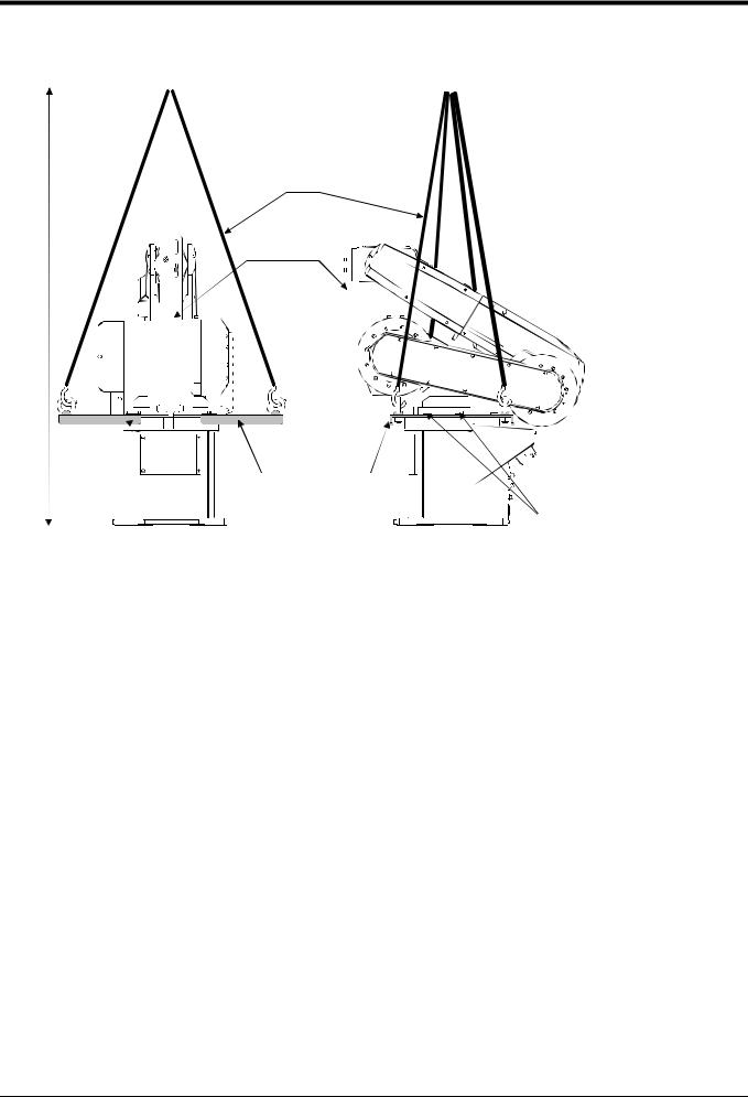
2.2.2 Transportation procedures (Transporting with a crane)
Wire
Fixing plate
1300
Suspension fitting
Hexagon socket bolt
(four M10 x 25,
four spring washers for M10)
Front |
Side |
Fig.2-2 Transportation procedures (transporting with a crane)
1)Attach the suspension fittings to the left and right sides of the shoulder section, and securely fix with bolts (four M10 x 25, four spring washers for M10). At this time, fix two of the suspension fitting's three holes at the side closest to the robot front.
2)Catch wires in the eye bolts installed on the suspension fittings, and quietly suspend the arm.
3)At this time, make sure that the wires, etc., do not interfere with the robot arm or covers. Always place cloth, etc., at interfering places.
4)When transferring to the installation place, take care not to apply vibration or impact.
5)After installing at the installation place, remove the above suspension fittings.
6)Always follow the above procedures and methods to transport the robot for secondary transportation, such as when changing the installation position.
If the arm is directly suspended without using the specified suspension fittings, or if it is suspended in the work posture, the configuration devices could be damaged, and the transportation workers will be subject to risk due to an inadequate center of gravity position.
Installation 2-7
2Unpacking to Installation
2.2.3 Installation procedures
4-M8×40 hexagon socket bolt (Four positions)
Spring washer Plain washer
4-φ9 installation hole |
2-φ6 holes |
|
(prepared holes for φ8 positioning pins) |
||
|
115 |
|
|
Robot front |
|
|
122 |
204 |
160 |
6.3a (Installation)
(Installation) |
96 |
|
102.5 |
|
|
6.3a |
|
205 |
115 |
140 |
Base bottom
Fig.2-3 Installation dimensions
1)The robot installation surface has been machine finished. Use the installation holes (4-φ9 holes) opened at the four corners of the base, and securely fix the robot with the enclosed installa- tion bolts (M8 x 40 hexagon socket bolts).
Installation of the robot arm is a very important step for ensuring the optimum functions of the robot. Observe the following points when design- ing.
2)Install the robot on a level surface.
3)It is recommended that the surface roughness of the table onto which the robot is to be installed by 6.3a or more. If the installation surface is rough, the contact with the table will be poor, and positional deviation could occur when the robot moves.
4)When installing, use a common table to prevent the position of the devices and jigs subject to robot work from deviating.
5)The installation surface must have sufficient strength to withstand the arm reaction during operation, and resistance against deformation and vibration caused by the static (dynamic) load of the robot arm and peripheral devices, etc.
6)Remove the fixing plates after installing the robot.
7)When the robot is installed by hanging from the ceiling or on the wall, the MEGDIR parameter must be changed. For more information about parameters and how to change the parameters, refer to the separate "Instruction Manual/ Detailed Explana-tion of Functions and Opera- tions".
2-8 Installation
2Unpacking to Installation
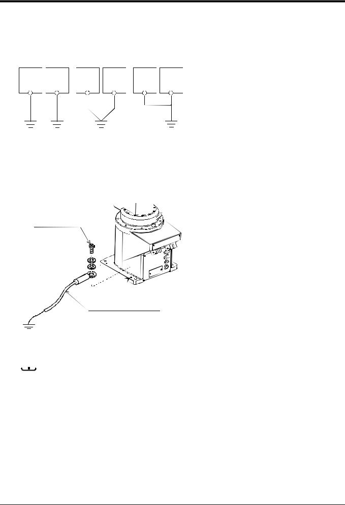
2.2.4 Grounding procedures
(1) Grounding methods
|
Controller |
|
Controller |
|
Controller |
|
Robot arm |
and |
Robot arm |
and |
Robot arm |
and |
|
personal |
personal |
personal |
||||
|
|
|
||||
|
computer |
|
computer |
|
computer |
(a) Dedicated grounding |
(b) Common grounding |
(c) Common grounding |
(Optimum) |
(Good) |
(Normal) |
Fig.2-4 Grounding methods
(2) Grounding procedures
Robot arm
M4×10, SW, PW
A
Robot grounding cable (AWG#11 (3.5mm2) or more) (Prepared by customer)
1)There are three grounding methods as shown in Fig. 2-4, but the dedicated grounding (Fig. 2-4 (a)) should be used for the robot arm and controller when possible. (Refer to the separate " Controller Setup, Basic Operation and Maintenance" for details on the controller grounding.)
2)Use Class D grounding (grounding resistance 100Ω or less).
Dedicated grounding separated from the other devices should be used.
3)Use a AWG#11(3.5mm2) or more stranded wire for the grounding wire. The grounding point should be as close to the robot arm and controller as possi- ble, and the length of the grounding wire should be short.
1)Prepare the grounding cable (AWG#11(3.5mm2) or more) and robot side installation screw and washer.
2)If there is rust or paint on the grounding screw section (A), remove it with a file, etc.
3)Connect the grounding cable to the grounding screw section.
Fig.2-5 Connecting the grounding cable

 CAUTION When installing the robot, be sure to allocate a sufficient maintenance space for connecting the cables between devices and replacing a backup battery at the rear of the robot.
Installation 2-9
2Unpacking to Installation
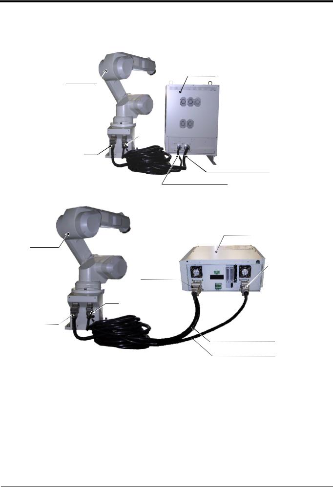
2.2.5 Connecting with the controller
<CR3-535M controller>
Controller
CN2
CN1
Motor power cable (7m)
CN1
Motor signal cable (7m)CN2
<CR2B-574 controller>
Controller
Robot arm
Motor signal
2
Motor power1 
CN2
CN1
Motor power cable (5m)
Motor signal cable (5m)
Fig.2-6 Connecting the machine cables
2-10 Installation
2Unpacking to Installation
Carry out the following procedure after installing the controller referring to the separate "Controller Setup, Basic Operation and Maintenance" manual.
Robot arm
Connector on the robot arm side
Hook
Projection
Connector on the machine cable side
1)Make sure that the power switch on the front of the controller is turned OFF.
2)Connect the machine cable to its corresponding connector on the robot arm side.
3) After connecting the connector, insert the hook attached to the connector on the machine cable side to the rear of the projection of the robot arm connector to fix securely in place.
Hook
* If you are using a CR2B-574 controller, also connect the applicable connector on the controller side according to
steps 2) and 3) above.
Projection
Hook
Projection
Minus screwdriver
 Padding
4)To remove the cable, insert a minus screwdriver into the hook while padding with a cloth, and remove the cable by lifting the hook.

 CAUTION

 CAUTION
The machine cable connectors are dedicated for the controller side and robot arm side, so take special care when connecting.
If connected incorrectly, the connector pins could bend or break. Thus, even if connected correctly, the robot will not operate correctly, creating a dangerous situation.
Take special care to the leading of the connection cable. If the cable is pulled with force or bent excessively, wires could break or the connector could be damaged.
Installation 2-11
2Unpacking to Installation
2.3 Setting the origin
The origin is set so that the robot can be used with a high accuracy. After purchasing the robot, always carry out this step before starting work. This step must also be carried out if the combination of robot and controller being used is changed.
There are several methods for setting the origin, but the origin data input method will be explained here. Refer to "5.5 Resetting the origin" on page 53 for the other methods.
The teaching pendant is required for this operation.
[Caution] If the origin data at shipment is erased due to out of battery, it is necessary to set the origin again. Refer to "5.5 Resetting the origin" on page 53 and reset the origin using the jig method or ABS origin method.
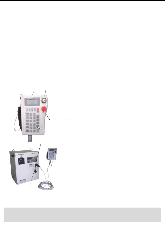
2.3.1 Installing the teaching pendant (T/B)
By using the "REMOVE T/B" switch, the T/B can be installed and removed while the controller's control power is ON. However, in this procedure, the teaching pendant will be installed with the control power OFF.
Refer to the separate "Controller setup, basic operation, and maintenance" for details on installing the teaching pendant with the control power ON.
(1) Installing with the control power OFF
DisplayLCD |
ENABLE/DISABLEswitch |
1) Confirm that the controller's power supply switch is OFF.
2) Connect the T/B connector to the RS-422 (T/B) connector on the controller.
3) Do not pull the cable with force or bend it excessively, as
the cable could break or the connector could be damaged.
Emergencystopswitch
4) Confirm that the [REMOVE T/B] switch on the side of the
controller is not depressed (is projected).
Operationkeys
5) Set the T/B [ENABLE/DISABLE] switch to "DISABLE".
Appearanceofteachingpendant REMOVE T/B switch
Teaching pendant (T/B)
<Figure shows the CR3-535M controller>
Connector
Fig.2-7 Installing the T/B (control power OFF)
[REMOVE T/B] switch
When using the robot with the T/B, this switch is used to invalidate the emergency stop from the T/B. This is also used to install the T/B with turning the controller's power supply ON.
2-12 Setting the origin

2Unpacking to Installation
2.3.2 Setting the origin with the origin data input method
(1) Confirming the origin data
●Origin data history table (Origin Data History) Serial No.ES804008
|
Date |
Default |
. . . |
. . . |
. . . |
|
|
|
|
|
|
|
|
|
|
|
|
|
|
V!#S29 |
|
|
|
|
|
|
|
|
|
|
06DTYY |
|
|
|
|
|
|
|
|
|
|
|
2?HL9X |
|
|
|
|
|
|
|
|
|
|
|
1CP55V |
|
|
|
|
|
|
|
|
|
|
|
|
T6!M$Y |
|
|
|
|
|
|
|
|
|
|
|
Z2IJ%Z |
|
|
|
|
|
|
|
|
|
|
A12%Z0 |
|
|
|
|
|
|
|
|
|
|
Method |
|
|
|
|
|
|
|
|
|
|
|
|
|
|
|
|
|
|
|
(O: AlphabetO, 0: Zero) |
|
|
|
Note) Meanings of symbols in method column
E: Jig method
N: Not used
SP: Not used
Fig.2-8 Origin data label (an example)
The origin data to be input is noted in the origin data sheet enclosed with the arm, or on the origin data history table attached to the back side of the shoulder coverB. (Refer to Fig. 2-8).
Referring to "5.3.2 Installing/removing the cover" on page 44, remove the shoulder coverB, and confirm the value.
The value given in the default setting column is the origin settings set with the calibration jig before shipment.

 WARNING Always install/remove the cover with the controller control power turned OFF. Failure to do so could lead to physical damage or personal injury should the robot start moving due to incorrect operations.
(2) Turning ON the control power

 CAUTION Confirm that there are no operators near the robot before turning the power ON.
1)Turn the controller [POWER] switch ON.
The control power will be turned ON, and "□ . 100" will appear on the STATUS NUMBER display on the front of the controller.
Setting the origin 2-13
2Unpacking to Installation
(3) Preparing the T/B
|
STATUS NUMBER |
CHANG DISP |
|
|
EMG.STOP |
|||||
|
|
|
|
|
|
|
|
|
|
|
|
MODE |
|
SVO ON |
|
START |
RESET |
|
|
||
|
TEACH |
|
|
|
|
|
|
|
|
|
AUTO |
AUTO |
|
|
|
|
|
|
|
||
(Op.) |
(Ext.) |
|
|
|
|
|
REMOVE T/B |
|||
|
|
|
SVO OFF |
|
STOP |
END |
|
|||
|
|
|
|
|
|
|
|
|
|
|
Next, prepare to use the T/B
1) Set the [MODE] switch on the front of the controller to "TEACH".
|
MODE |
|
TEACH |
AUTO |
AUTO |
(Op.) |
(Ext.) |
DISABLE ENABLE
DI SABLE ENABLE
P8TB-TE
EMG. STOP
2)Set the T/B [ENABLE/DISABLE] switch to "ENABLE". The menu selection screen will appear.
The following operations are carried out with the T/B.
Operating from the T/B
Always set the [MODE] switch (mode selection key switch) on the front of the controller to "TEACH", and then set the T/B [ENABLE/DISABLE] switch to "ENABLE".
When the T/B is valid, only operations from the T/B are possible. Operations from the controller or external signals will not be accepted.
When T/B operations are mistaken
The displayed screen will return to the "menu selection screen" when the [MENU] key is pressed. Carry out the operations again from this screen. Operations can also be carried out again by setting the T/B [ENABLE/ DISABLE] switch to "DISABLE" once and then setting to "ENABLE".
2-14 Setting the origin
Loading...