


SPLIT-TYPE, HEAT PUMP AIR CONDITIONERS
No. OB371
SERVICE MANUAL
Wireless type
Models
MSZ-FA25VA - E1 (WH)
MSZ-FA35VA - E1 (WH)
CONTENTS
|
1. TECHNICAL CHANGES ·············· |
|
2. PART NAMES AND FUNCTIONS·········· |
|
3. SPECIFICATION················· |
|
4. NOISE CRITERIA CURVES ············ |
|
5. OUTLINES AND DIMENSIONS ··········· |
Indication of model name |
6. WIRING DIAGRAM ················ |
MSZ-FA25VA - E1 |
7. REFRIGERANT SYSTEM DIAGRAM ········ |
MSZ-FA35VA - E1 |
8. SERVICE FUNCTIONS ·············· |
|
9. TROUBLESHOOTING··············· |
|
10. DISASSEMBLY INSTRUCTIONS·········· |
|
11. PARTS LIST··················· |
|
12. OPTIONAL PARTS················ |
NOTE:
This service manual describes technical data of the indoor units.
•As for outdoor units MUZ-FA25VA- E1 , MUZ-FA35VA- E1 , MUZ-FA25VAH- E1 and MUZ-FA35VAH- E1 , refer to service manual OB372.
•As for outdoor units MXZ-3A54VA- E1 , MXZ-4A71VA- E1 refer to service manual OB377.
1 
 TECHNICAL CHANGES
MSZ-A09YV |
- E1 |
MSZ-FA25VA |
- E1 |
MSZ-A12YV |
- E1 |
MSZ-FA35VA |
- E1 |
1.Indication of capacity has been changed.(BTU base kW base)
2.Controller method between indoor and outdoor has been changed.
3.Power supply method has been changed (change to supply from outdoor unit).
4.Power supply cord has been removed.
5.Indoor electronic control P.C. board has been changed.
6.Position of terminal block has been changed.
7.Indoor fan motor has been changed. ( AC DC)
8.Indoor heat exchanger has been changed.
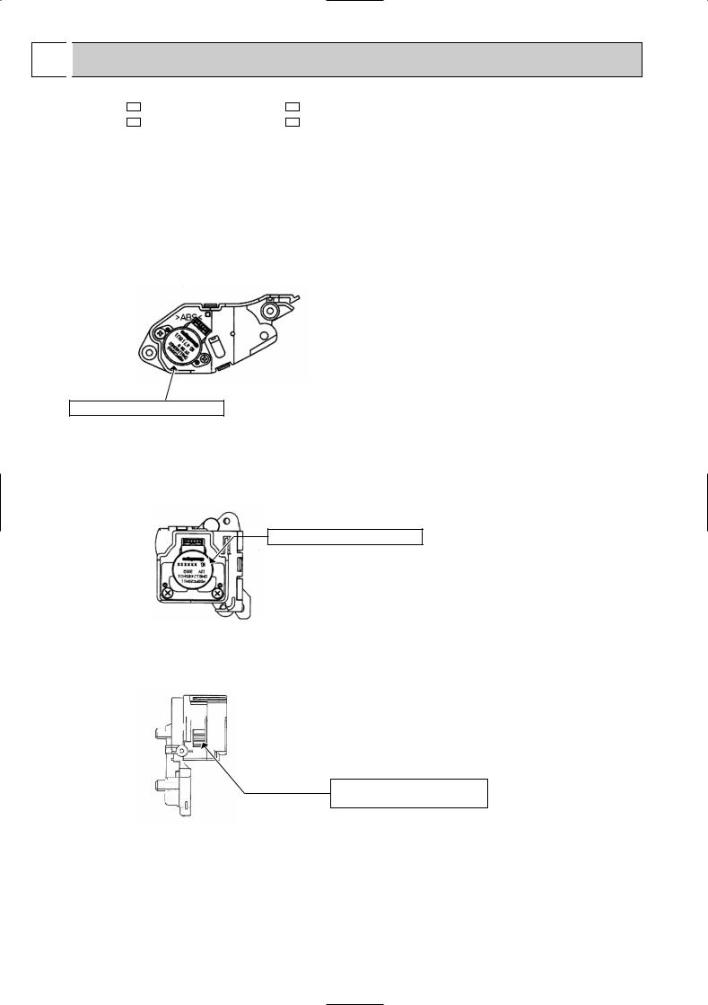
9.The horizontal vane motor unit has been changed.
An external gear is added to the generalized stepping motor.
The unit is structured so that the driving torque and stopping torque would increase.
Generalized stepping motor
NOTE: Do not remove the vane motor from the motor unit.
Do not disassemble the horizontal vane motor unit.
10.The vertical vane motor unit has been added.
An external gear is added to the generalized stepping motor.
The unit is structured so that the driving torque and stopping torque would increase.
Generalized stepping motor
NOTE: Do not remove the vane motor from the motor unit.
Do not disassemble the vertical vane motor unit.
11. Front panel driving motor unit which opens and closes the front panel has been added.
Front panel opening/closing output gear
NOTE: Do not disassemble the front panel driving motor unit.
12.PLASMA DEODORIZING/AIR PURIFYING filter units have been added.
13.i-see Sensor has been added.
(i-see control operation and AREA setting have been added.)
14.Air cleaning filer has been removed.
15.Signal of remote controller has been changed. (It is not available for the conventional models.)
16.Symbol on terminal block has been changed (to S1/S2/S3).
2
2 |
PART NAMES AND FUNCTIONS |
|
|
|
INDOOR UNIT |
|
|
|
|
MSZ-FA25VA - E1 |
|
|
|
|
MSZ-FA35VA - E1 |
|
|
|
|
|
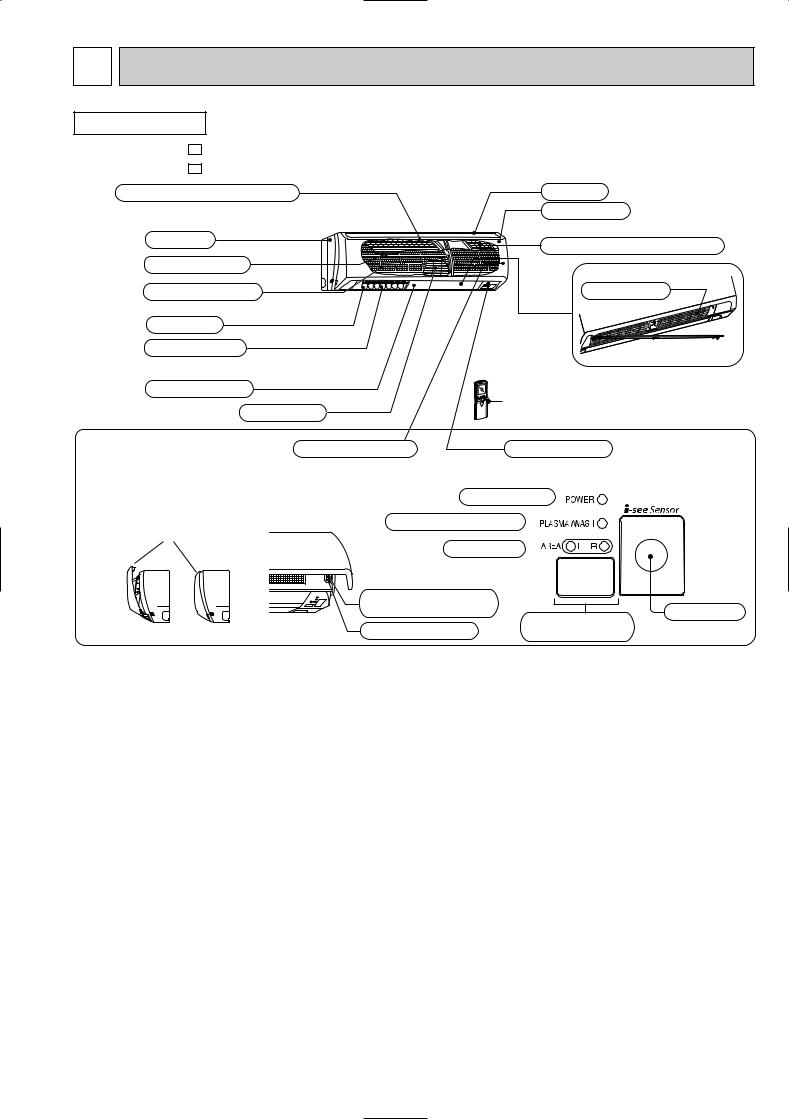
PLASMA AIR PURIFYING filter |
|
Air inlet |
|
|
|
|
Front panel |
|
|
Panel |
|
PLASMA DEODORIZING filter |
|
|
|
|
||
|
Heat exchanger |
|
|
|
|
Anti-mold air filter |
|
Fan guard |
|
|
Air outlet |
|
|
|
|
Vertical vane |
|
|
|
|
Horizontal vane |
|
Remote controller |
|
|
Line flow fan |
|
||
|
|
|
||
|
Auto front panel |
Operation section |
Display section |
|
When the unit starts operating, the |
|
|||
(When the front panel is opened) |
|
|
||
front panel opens automatically to |
|
|
||
draw in air. When the unit stops |
POWER lamp |
|
||
operating, the front panel closes |
|
|||
automatically. |
PLASMA/WASH lamp |
|
||
|
Auto front panel |
|
||
|
|
|
|
|
|
|
AREA lamp |
|
|
|
|
Emergency operation |
|
|
|
|
switch |
Remote control |
i-see Sensor |
|
|
WASH reset switch |
|
|
|
<Open> <Closed> |
receiving section |
|
|
AREA lamp indicate AREA setting
In AREA setting, the horizontal air flow direction changes automatically according
to the detection of i-see Sensor which detects the floor/ wall temperature to air-condition the room evenly.
i-see control operation
i-see sensor constantly measure floor/wall temperature to automatically adjust to the set temperature by estimating the temperature
actually perceived by a person inside the room ("sensible temperature").
3
|
|
|
|
|
|
MSZ-FA25VA - E1 |
|
|
|
||
MSZ-FA35VA - E1 |
|
|
MSZ-FA25VA - E1 |
|
|
ACCESSORIES |
|
|
|
|
|
|
|
|
MSZ-FA35VA - E1 |
|
|
|
|
|
|
|
|
|
|
1 |
Installation plate |
1 |
|
|
|
|
|
|
|
|
|
2 |
Installation plate fixing screw 4 o 25 mm |
5 |
|
|
|
|
|
|
|
|
|
3 |
Remote controller holder |
1 |
|
|
|
|
|
|
|
|
|
4 |
Fixing screw for 3 3.5 o 1.6 mm (Black) |
2 |
|
|
|
|
|
|
|
|
|
5 |
Battery (AAA) for remote controller |
2 |
|
|
|
|
|
|
|
|
|
6 |
Wireless remote controller |
1 |
|
|
|
|
|
|
|
|
|
7 |
Felt tape (Used for left or left-rear piping) |
1 |
|
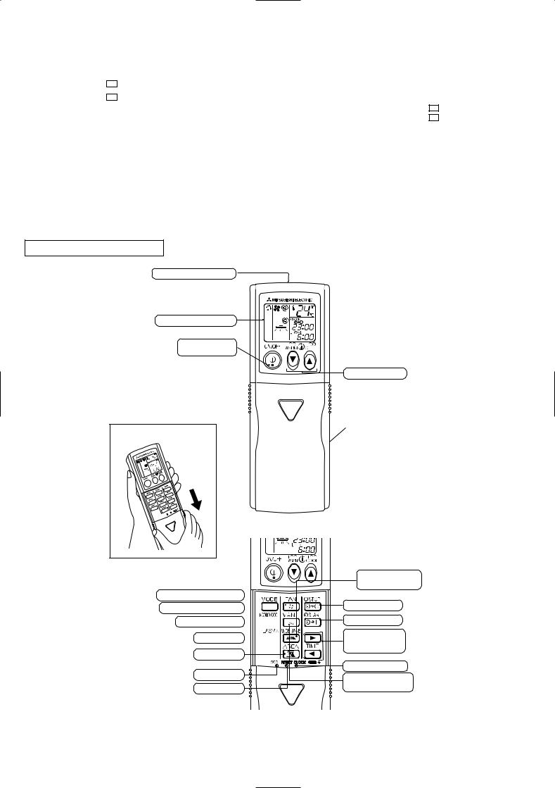
REMOTE CONTROLLER
Signal transmitting section
Operation display section
OPERATE/STOP (ON/OFF) button
Open the front lid. |
FAN SPEED CONTROL button
OPERATION SELECT button
ECONO COOL button


PLASMA button 

AREA button
i-see button RESET button
Temperature buttons
Indication of remote controller model is on back
WIDE VANE button (Vertical vane button)
OFF-TIMER button
ON-TIMER button
TIME SET buttons
FORWARD button
BACKWARD button
CLOCK SET button
VANE CONTROL button (Horizontal vane button)
4
3 
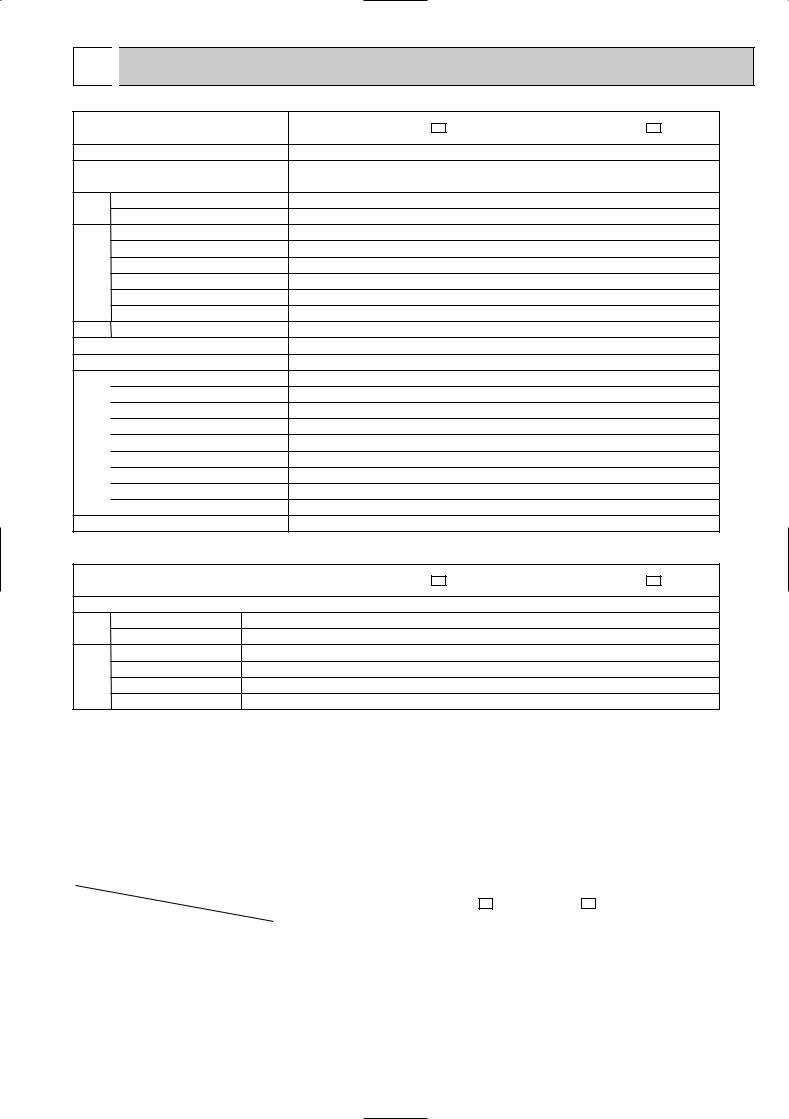
 SPECIFICATION
Indoor model
Function
Power supply
|
Air flow(Super High) |
|
K /h |
Capacity Air flow(HighW/Med.W/LowW) |
|
K /h |
|
|
Power outlet |
|
A |
Electrical data |
Running current 1 |
|
A |
Power input 1 |
|
W |
|
|
|
||
|
Auxiliary heater |
|
A(kW) |
|
Power factor 1 |
|
% |
|
Fan motor current 1 |
|
A |
Fan motor |
Model |
|
|
|
Dimensions WOHOD |
|
mm |
|
Weight |
|
kg |
|
Air direction |
|
|
|
Sound level(Super High) |
|
dB(A) |
|
|
||
|
Sound level(HighW/Med.W/LowW) |
|
dB(A) |
Special remarks |
Fan speed(Super High) |
|
rpm |
Fan speed regulator |
|
rpm |
|
|
Fan speed(HighW/Med.W/LowW) |
|
|
|
Thermistor RT11(at25:) |
|
k" |
|
|
||
|
Thermistor RT12(at25:) |
|
k" |
|
Thermistor RT13(at25:) |
|
k" |
|
Remote controller model |
|
|
MSZ-FA25VA - E1 |
MSZ-FA35VA - E1 |
||||
Cooling |
|
Heating |
Cooling |
|
Heating |
|
|
||||
Single phase |
Single phase |
||||
230V,50Hz |
230V,50Hz |
||||
594 |
|
612 |
594 |
|
612 |
474W/354W/252W |
|
498W/384W/264W |
474W/354W/258W |
|
498W/384W/276W |
|
10 |
|
10 |
||
0.25 |
0.25 |
||||
|
33 |
|
33 |
||
|
— |
|
— |
||
|
57 |
|
57 |
||
0.25 |
0.25 |
||||
RC0J40-EB |
RC0J40-EB |
||||
780O298O198 |
780O298O198 |
||||
|
10 |
|
10 |
||
|
4 |
|
4 |
||
|
42 |
|
42 |
||
36W/29W/21W |
36W/29W/22W |
||||
1,220 |
|
1,250 |
1,220 |
|
1,250 |
1,010W/800W/610W |
|
1,050W/850W/640W |
1,010W/800W/630W |
|
1,050W/850W/660W |
|
4 |
|
4 |
||
|
10 |
|
10 |
||
|
10 |
|
10 |
||
|
10 |
|
10 |
||
KM05A |
KM05A |
||||
|
|
|
|
|
|
When outdoor unit is MXZ type.
Indoor model
Function
Capacity Air flow(Super High)
Air flow(HighW/Med.W/LowW)
Special remarks |
Sound level(Super High) |
|
Sound level(HighW/Med.W/LowW) |
||
|
||
|
Fan speed(Super High) |
|
|
Fan speed(HighW/Med.W/LowW) |
|
MSZ-FA25VA - E1 |
MSZ-FA35VA - E1 |
||||
|
Cooling |
|
Heating |
Cooling |
|
Heating |
|
|
|
||||
K /h |
546 |
|
540 |
642 |
||
K /h |
450W/348W/252W |
|
420W/372W/264W |
516W/390W/258W |
|
522W/402W/276W |
dB(A) |
|
42 |
|
42 |
||
dB(A) |
36W/29W/21W |
36W/29W/22W |
||||
rpm |
1,130 |
|
1,120 |
1,300 |
||
rpm |
960W/790W/610W |
|
910W/830W/640W |
1,080W/860W/630W |
|
1,090W/880W/660W |
NOTE : Test conditions are based on ISO 5151 |
|
||
Cooling : Indoor |
Dry-bulb temperature 27:Wet-bulb temperature 19: |
||
Outdoor Dry-bulb temperature 35:Wet-bulb temperature 24: |
|||
Heating : Indoor |
Dry-bulb temperature 20:Wet-bulb temperature 15: |
||
Outdoor Dry-bulb temperature 7: Wet-bulb temperature 6: |
|||
Refrigerant piping length (one way): 5m |
|
||
w Reference value |
|
|
|
1 Measured under rated operating frequency. |
|
||
Specifications and rating conditions of main electric parts |
|||
INDOOR UNIT |
|
|
|
|
|
|
|
Item |
Model |
|
MSZ-FA25VA - E1 MSZ-FA35VA - E1 |
|
|
|
|
|
|
|
|
Fuse |
(F11) |
|
T3.15AL250V |
|
|
|
|
Front panel driving motor |
(MP) |
|
NSEJ001DA1 12V DC 100" (at 25˚C) |
i-see Sensor motor |
(MT) |
|
MP20Z 12V DC 300" (at 25˚C) |
Horizontal vane motor |
(MV1) |
|
MSBPC20M16 12V DC 250" (at 25˚C) |
Vertical vane motor |
(MV2) |
|
MSBPC20M11 12V DC 300" (at 25˚C) |
Varistor |
(NR11) |
|
ERZV14D471 |
i-see Sensor |
(RR) |
|
A2TPMI334F0V50HSOBA060P5L1J4S 5V DC |
|
|
|
|
Terminal block |
(TB) |
|
3P |
|
|
|
|
|
|
|
5 |

4 NOISE CRITERIA CURVES
MSZ-FA25VA - E1
FAN SPEED FUNCTION SPL(dB(A)) |
LINE |
COOLING 42
Super High
HEATING 42
Test conditions,
|
Cooling : Dry-bulb temperature 27: Wet-bulb temperature 19: |
||||||||
|
Heating : Dry-bulb temperature 20: Wet-bulb temperature 15: |
||||||||
BAR |
90 |
|
|
|
|
|
|
|
|
|
|
|
|
|
|
|
|
|
|
MICRO |
80 |
|
|
|
|
|
|
|
|
|
|
|
|
|
|
|
|
|
|
0.0002 |
70 |
|
|
|
|
|
|
|
NC-70 |
|
|
|
|
|
|
|
|
||
dB re |
60 |
|
|
|
|
|
|
|
|
LEVEL, |
|
|
|
|
|
|
|
|
|
|
|
|
|
|
|
|
|
NC-60 |
|
50 |
|
|
|
|
|
|
|
|
|
PRESSURE |
|
|
|
|
|
|
|
|
|
|
|
|
|
|
|
|
|
NC-50 |
|
40 |
|
|
|
|
|
|
|
|
|
|
|
|
|
|
|
|
|
NC-40 |
|
SOUND |
|
|
|
|
|
|
|
|
|
30 |
|
|
|
|
|
|
|
|
|
BAND |
|
|
|
|
|
|
|
|
NC-30 |
20 |
APPROXIMATE |
|
|
|
|
|
|
||
OCTAVE |
|
|
|
|
|
|
|||
THRESHOLD OF |
|
|
|
|
|
|
|||
|
|
|
|
|
|
|
|||
|
HEARING FOR |
|
|
|
|
|
NC-20 |
||
|
CONTINUOUS |
|
|
|
|
|
|
||
10 |
NOISE |
|
|
|
|
|
|
|
|
|
63 |
125 |
250 |
500 |
1000 |
2000 |
4000 |
8000 |
|
|
|
||||||||
BAND CENTER FREQUENCIES, Hz
MSZ-FA35VA - E1
FAN SPEED FUNCTION |
SPL(dB(A)) |
LINE |
COOLING |
42 |
|
Super High |
42 |
|
HEATING |
|
Test conditions,
Cooling : Dry-bulb temperature 27: Wet-bulb temperature 19: Heating : Dry-bulb temperature 20: Wet-bulb temperature 15:
BAR |
90 |
|
|
|
|
|
|
|
|
|
|
|
|
|
|
|
|
|
|
MICRO |
80 |
|
|
|
|
|
|
|
|
|
|
|
|
|
|
|
|
|
|
0.0002 |
70 |
|
|
|
|
|
|
|
NC-70 |
|
|
|
|
|
|
|
|
||
dB re |
60 |
|
|
|
|
|
|
|
|
LEVEL, |
|
|
|
|
|
|
|
|
|
|
|
|
|
|
|
|
|
NC-60 |
|
50 |
|
|
|
|
|
|
|
|
|
PRESSURE |
|
|
|
|
|
|
|
|
|
|
|
|
|
|
|
|
|
NC-50 |
|
40 |
|
|
|
|
|
|
|
|
|
|
|
|
|
|
|
|
|
NC-40 |
|
SOUND |
|
|
|
|
|
|
|
|
|
30 |
|
|
|
|
|
|
|
|
|
BAND |
|
|
|
|
|
|
|
|
NC-30 |
20 |
APPROXIMATE |
|
|
|
|
|
|
||
OCTAVE |
|
|
|
|
|
|
|||
THRESHOLD OF |
|
|
|
|
|
|
|||
|
|
|
|
|
|
|
|||
|
HEARING FOR |
|
|
|
|
|
NC-20 |
||
|
CONTINUOUS |
|
|
|
|
|
|
||
10 |
NOISE |
|
|
|
|
|
|
|
|
|
63 |
125 |
250 |
500 |
1000 |
2000 |
4000 |
8000 |
|
|
|
||||||||
BAND CENTER FREQUENCIES, Hz
INDOORUNIT
WALL
1m
0.8m
MICROPHONE
6
5 
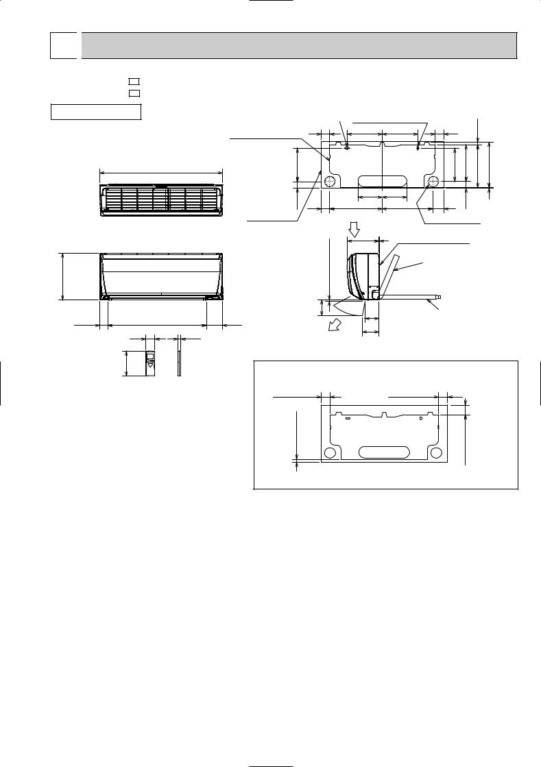
 OUTLINES AND DIMENSIONS
MSZ-FA25VA - E1 |
Unit : mm |
MSZ-FA35VA - E1 |
|
INDOOR UNIT |
|
11o26 Oblong hole |
11o20 Oblong hole |
|
|
|
|
|
|||
|
|
|
|
|
|
|
|||||
|
|
Installation plate |
55 |
225 |
|
225 |
|
55 |
|
14 |
|
|
|
|
|
|
|
|
|
|
|
|
|
|
780 |
215 |
|
|
|
|
|
214 |
234 |
273.5 |
287.5 |
|
|
|
|
|
|
|
|
|
|
|
|
|
|
41.5 |
|
155 |
|
155 |
|
|
42.5 |
|
3 |
|
|
55 |
335 |
|
320 |
|
70 |
|
|||
|
|
Indoor unit |
|
Air in |
|
|
|
Wall hole |
[65 |
|
|
|
|
|
|
|
|
|
|
|
|||
|
|
|
more |
198 |
5 |
Installation plate |
|
|
|
||
|
|
|
|
|
|
{ |
Liquid line [6.35 - 0.5m |
||||
|
|
|
|
|
|
|
|||||
|
|
|
7 or |
|
|
|
Gas line [9.52 - 0.43m |
||||
298 |
|
|
|
|
|
Insulation [35 O.D |
|||||
|
|
|
|
|
|
[19 I.D |
|||||
|
|
|
100 |
|
|
|
|
Drain hose [16 |
|||
|
|
|
|
|
|
|
(Connected part O.D) |
||||
|
|
|
|
|
|
|
|
||||
53.5 |
624.5 |
102 |
|
90 |
|
|
|
Insulation [28 |
|||
|
106 |
|
|
|
|||||||
58 |
|
19 |
|
|
|
|
|
|
|
|
|
|
Air out |
|
|
|
|
|
|
|
|
||
|
|
|
|
|
|
|
|
|
|
|
|
159 |
moreor55w |
leftleft,ofcaseInwback, or (usingpipingunderleft spacer), moreor113 |
moreor10 |
||
Required space (Indoor unit) |
|
|
Wireless remote controller |
75 or more |
|
75 or more |
|
7
6 
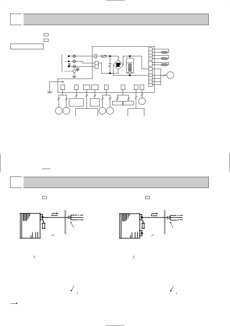
 WIRING DIAGRAM
MSZ-FA25VA |
- E1 |
|
MSZ-FA35VA |
- E1 |
MODELS WIRING DIAGRAM |
INDOOR UNIT |
|
|
|
|
|
|
|
|
INDOOR ELECTRONIC |
|
|
4 |
|
|
|
|
|
|
|
|
|
|
|
|
|
|
|
|
|
RT13 |
|||
|
|
|
TB |
BLK |
TAB3 |
F11 |
|
|
CONTROL P.C. BOARD |
CN |
3 |
|
|
|||
|
|
230V~ |
|
|
|
|
|
|
|
|
||||||
|
|
S1 |
|
|
|
|
|
|
|
112 |
2 |
|
|
RT12 |
||
|
|
|
S2 |
|
|
|
DB111 |
|
|
|
|
|
1 |
|
|
|
TO OUTDOOR |
|
|
BLU |
|
|
|
T111 |
|
|
|
|
|
|
|||
|
|
2 |
|
|
|
|
|
CN |
|
|
|
|||||
UNIT |
|
12-24V |
S3 |
RED |
NR11 |
|
|
|
|
|
|
|
|
RT11 |
||
|
|
|
|
|
|
|
111 |
|
|
|||||||
CONNECTING |
|
1 |
|
|
|
|
|
|
|
RED |
|
|
||||
|
|
|
|
|
|
|
|
|
|
|
|
1 |
|
|
||
|
|
|
|
|
CN201 |
|
|
|
|
|
|
|
|
|
||
|
|
|
|
|
|
|
|
|
|
|
|
|
|
|
||
|
|
|
|
|
|
|
|
|
|
|
|
2 |
BLK |
5 |
|
|
|
|
|
|
|
|
|
|
|
|
|
|
|
MF |
|||
|
|
|
|
|
|
|
|
|
|
|
|
|
3 |
|||
|
|
|
|
|
|
|
|
|
|
|
|
|
WHT |
|
||
|
|
|
|
|
|
|
|
|
|
|
|
|
4 |
|
|
|
|
|
|
|
|
|
|
|
|
|
|
|
|
YLW |
|
|
|
|
|
LD104 |
|
|
|
|
|
|
|
|
|
|
5 |
|
|
|
|
|
|
|
|
|
|
|
|
|
|
|
BLU |
|
|
||
|
|
CN |
CN |
LD |
LD |
CN |
|
|
CN |
CN |
CN |
|
6 |
|
|
|
GRN |
|
|
|
|
|
|
|
|||||||||
|
|
|
|
CN211 |
|
|
|
|||||||||
151 |
1R1 |
101(A) |
105(T) |
110 |
|
|
1T1 |
1T2 |
1U1 |
|
|
|
|
|||
|
|
|
|
|
|
|
||||||||||
|
5 |
5 |
2 |
8 |
3 |
5 |
4 |
3 |
3 |
2 |
|
5 |
|
|
|
|
|
|
|
|
|
|
|
||||||||||
|
|
|
INTERLOCK |
|
SW P.C. |
|
PLASMA_A PLASMA_D |
|
MP |
|
|
|
|
|
||
|
|
|
SWITCH(FAN) |
|
BOARD |
|
|
|
|
|
|
|
|
|||
|
|
|
|
|
|
|
|
|
|
|
|
|
|
|
||
|
MV1 MV2 |
POWER MONITOR |
|
MT RR |
SAFETY DEVICE |
|
|
|
|
|
|
|
RECEIVER P.C. BOARD |
(PLASMA UNIT) |
|
|
|
||
|
|
|
|
|
|
|
|
|
|
SYMBOL |
NAME |
SYMBOL |
|
NAME |
|
SYMBOL |
NAME |
||
DB111 |
DIODE STACK |
MV2 |
VANE MOTOR (VERTICAL) |
|
RT12 |
INDOOR COIL THERMISTOR (MAIN) |
|||
F11 |
FUSE (T3.15AL250V) |
NR11 |
VARISTOR |
|
|
RT13 |
INDOOR COIL THERMISTOR (SUB) |
||
MF |
INDOOR FAN MOTOR |
PLASMA_A |
PLASMA AIR PURIFYING FILTER UNIT |
|
T111 |
TRANSFORMER |
|||
MP |
FRONT PANEL DRIVING MOTOR |
PLASMA_D |
PLASMA DEODORIZING FILTER UNIT |
|
TB |
TERMINAL BLOCK |
|||
MT |
i-see Sensor MOTOR |
RR |
i-see Sensor |
|
|
|
|
||
MV1 |
VANE MOTOR (HORIZONTAL) |
RT11 |
ROOM TEMPERATURE THERMISTOR |
|
|
|
|||
NOTE:1. About the outdoor side electric wiring refer to the outdoor unit electric wiring diagram for servicing.
2.Use copper conductors only. (For field wiring)
3.Symbols below indicate.
/: Terminal block,  : Connector
7 
 REFRIGERANT SYSTEM DIAGRAM
MSZ-FA25VA - E1 |
|
MSZ-FA35VA - E1 |
Unit : mm |
INDOOR UNIT |
Refrigerant pipe [9.52 |
INDOOR UNIT |
Refrigerant pipe [9.52 |
|
|
||
|
|
||
|
(with heat insulator) |
|
(with heat insulator) |
Indoor |
Indoor coil |
|
Indoor |
Indoor coil |
|
thermistor |
|
thermistor |
|||
heat |
RT12(main) |
|
heat |
RT12(main) |
|
exchanger |
Flared connection |
exchanger |
|||
|
Flared connection |
|
|
|
|
|
|
|
|
|
|
|
|
|
|
|
|
|
|
|
|
|
|
|
|
|
|
|
|
|
|
|
|
|
|
|
|
|
|
|
|
|
|
|
Indoor coil |
|
|
|
|
|
|
|
|
|
|
|
|
|
Indoor coil |
|
|
|
|
|
|
|
|
||||||||||||||
|
|
|
thermistor |
|
|
|
|
|
|
|
|
|
|
|
|
|
thermistor |
|
|
|
|
|
|
|
|
||||||||||||||
|
|
|
RT13(sub) |
|
|
|
|
|
|
|
|
|
|
|
|
|
RT13(sub) |
|
|
|
|
|
|
|
|
||||||||||||||
|
|
|
|
|
|
|
|
|
|
|
|
|
|
|
|
|
|
|
|
|
|
|
|
|
|
|
|
|
|
|
|
|
|
|
|
|
|
|
|
Room temperature |
|
|
|
|
|
|
|
|
|
|
|
Room temperature |
|
|
|
|
|
|
|
|
|||||||||||||||||||
thermistor |
|
|
|
|
|
|
|
|
|
|
thermistor |
|
|
|
|
|
|
|
|
||||||||||||||||||||
RT11 |
|
|
|
|
|
|
|
|
|
|
RT11 |
|
|
|
|
|
|
|
|
||||||||||||||||||||
|
|
|
|
|
|
|
|
|
|
|
|
Flared connection |
|
|
|
|
|
|
|
|
|
|
|
|
Flared connection |
||||||||||||||
|
|
|
|
|
|
|
|
|
|
|
|
|
|
|
|
|
|
|
|
|
|
|
|
||||||||||||||||
|
|
|
|
|
|
|
|
|
|
|
|
|
|
|
|
|
|
|
|
|
|
|
|
||||||||||||||||
|
|
|
|
|
|
|
|
|
|
|
|
|
|
|
|
|
|
|
|
|
|
|
|
||||||||||||||||
|
|
|
|
|
|
|
|
|
|
|
|
|
|
|
|
|
|
|
|
|
|
|
|
||||||||||||||||
|
|
|
|
|
|
|
|
|
|
|
|
|
|
|
|
|
|
|
|
|
|
|
|
|
|
|
|
|
|
|
|
|
|
|
|
|
|
|
|
|
|
|
|
|
|
|
|
|
|
|
|
|
|
|
|
|
|
|
|
|
|
|
|
|
|
|
|
|
|
|
|
|
|
|
|
|
|
|
|
Refrigerant flow in cooling |
|
|
|
Refrigerant pipe [6.35 |
|
|
|
|
|
|
|
|
|
|
|
|
|
Refrigerant pipe [6.35 |
|||||||||||||||||||||
|
|
|
(with heat insulator) |
|
|
|
|
|
|
|
|
|
|
|
|
|
(with heat insulator) |
||||||||||||||||||||||
|
|
|
|
|
|
|
|
|
|
|
|
|
|
|
|
|
|
|
|
|
|
|
|
|
|
||||||||||||||
 Refrigerant flow in heating
8
8 
 SERVICE FUNCTIONS
MSZ-FA25VA - E1
MSZ-FA35VA - E1
8-1. TIMER SHORT MODE
For service, set time can be shortened by short circuit of JPG and JPS the electronic control P.C. board. The time will be shortened as follows. (Refer to 9-7.)
Set time : 1-minute 1-second
Set time : 3-minute 3-second (It takes 3 minutes for the compressor to start operation. However, the starting time is shortened by short circuit of JPG and JPS.)
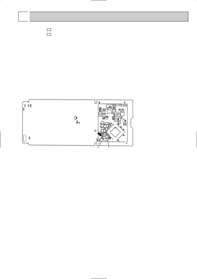
8-2. P.C. BOARD MODIFICATION FOR INDIVIDUAL OPERATION
A maximum of 4 indoor units with wireless remote controllers can be used in a room.
In this case, to operate each indoor unit individually by each remote controller, P.C. boards of remote controller must be modified according to the number of the indoor unit.
How to modify the remote controller P.C. board
Remove batteries before modification.
The board has a print as shown below :
Remote controller model : KM05A
NOTE : For remodelling, take out the batteries and press the OPERATE/STOP(ON/OFF) button twice or 3 times at first.
After finish remodelling, put back the batteries then press the RESET button.
J1 J2
The P.C. board has the print “J1” and “J2”. Solder “J1” and “J2” according to the number of indoor unit as shown in Table 1. After modification, press the RESET button.
Table 1
|
1 unit operation |
2 units operation |
3 units operation |
4 units operation |
No. 1 unit |
No modification |
Same as at left |
Same as at left |
Same as at left |
|
|
|
|
|
No. 2 unit |
– |
Solder J1 |
Same as at left |
Same as at left |
|
|
|
|
|
No. 3 unit |
– |
– |
Solder J2 |
Same as at left |
|
|
|
|
|
No. 4 unit |
– |
– |
– |
Solder both J1 and J2 |
|
|
|
|
|
How to set the remote controller exclusively for particular indoor unit.
After you turn the breaker ON, the first remote controller that sends the signal to the indoor unit will be regarded as the remote controller for the indoor unit.
The indoor unit will only accepts the signal from the remote controller that has been assigned to the indoor unit once they are set.
The setting will be cancelled if the breaker has turned off, or the power supply has shut down. Please conduct the above setting once again after the power has restored.
8-3. AUTO RESTART FUNCTION
When the indoor unit is controlled with the remote controller, the operation mode, the set temperature, and the fan speed are memorized by the indoor electronic control P.C. board. The “AUTO RESTART FUNCTION” sets to work the moment power has restored after power failure. Then, the unit will restart automatically.
Operation
1 If the main power has been cut, the operation settings remain.
2After the power is restored, the unit restarts automatically according to the memory. (However, it takes at least 3 minutes for the compressor to start running.)
9
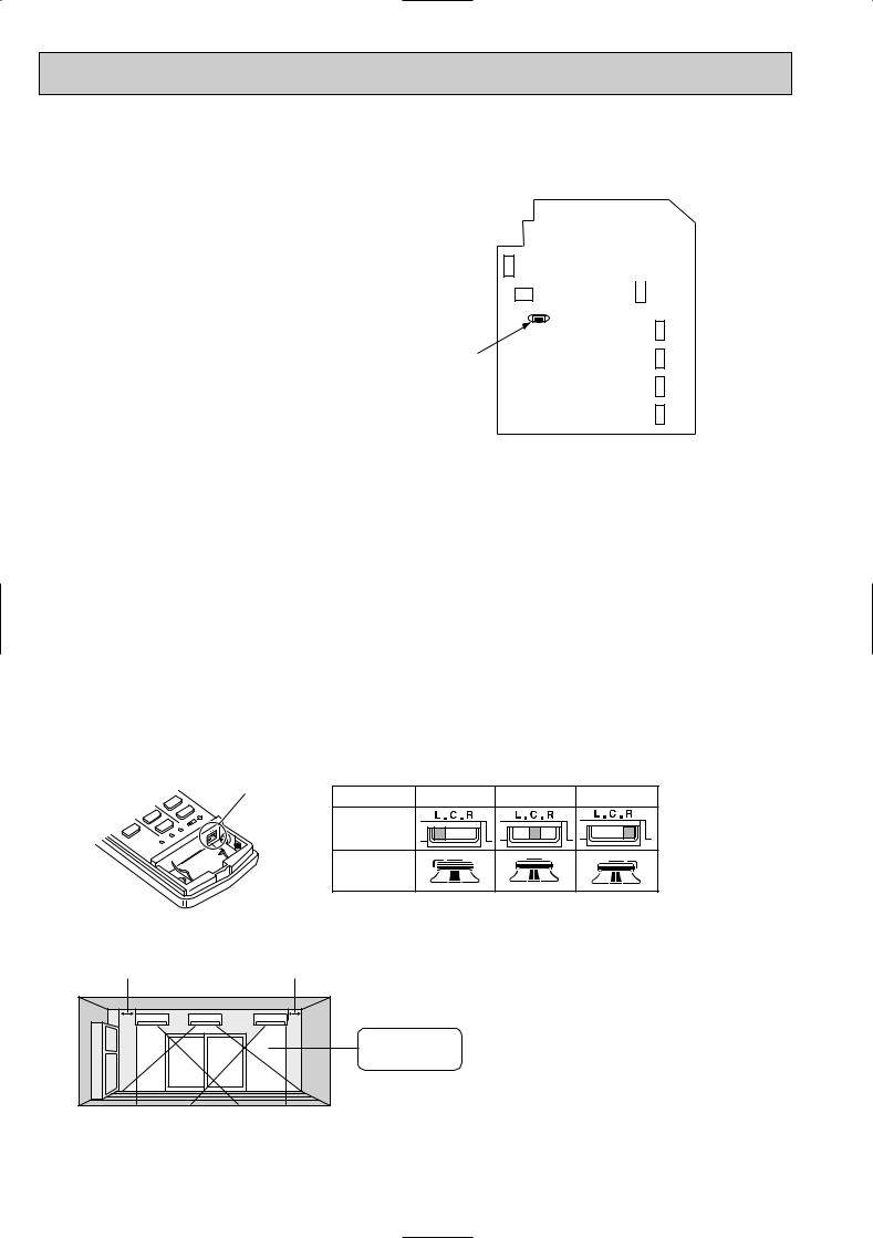
How to release “AUT O RESTART FUNCTION”
1Turn off the main power for the unit.
2Solder the Jumper wire to JR07 on the indoor electronic control P.C. board. (Refer to 9-7.)
CN130
IC156
JR07
CN212 
 CN151 CN1T2 CN1T1 CN112 CN1R1 CN211
NOTE:
•The operation settings are memorized when 10 seconds have passed after the indoor unit was operated with the remote controller.
•If main power is turned OFF or a power failure occurs while AUTO START/STOP timer is active, the timer setting is cancelled.
•If the unit has been off with the remote controller before power failure, the auto restart function does not works as the power button of the remote controller is off.
•To prevent breaker off due to the rush of starting current, systematize other home appliance not to turn on at the same time.
•When some air conditioners are connected to the same supply system, if they are operated before power failure, the starting current of all the compressors may flow simultaneously at restart.
Therefore, the special counter-measures are required to prevent the main voltage-drop or the rush of the starting current by adding to the system that allows the units to start one by one.
8-4. Remote controller
Be sure to set the slide switch inside the remote controller to an appropriate position in accordance with the installed position of the indoor unit. If the switch is not set correctly, the air conditioner may not function properly.
Side swich
Where is the indoor unit installed in your room?
Area |
Left |
Center |
Right |
Position of the slide switch
Display on the remote controller
Installed at left , if the |
Installed at right , if the |
distance is not more |
distance is not more |
than 50 cm. |
than 50 cm. |
(Left) |
(Center) |
(Right) |
Is the indoor unit installed at right, left or center?
NOTE:If the indoor unit is installed more than 50 cm away from the side walls, cabinets or other nearby objects, set the slide switch to the “center” position.
10
9 
 TROUBLESHOOTING
MSZ-FA25VA - E1
MSZ-FA35VA - E1
9-1. Cautions on troubleshooting
1.Before troubleshooting, check the following:
1)Check the power supply voltage.
2)Check the indoor/outdoor connecting wire for mis-wiring.
2.Take care the following during servicing.
1)Before servicing the air conditioner, be sure to turn off the unit first with the remote controller, and then after confirming the horizontal vane is closed, turn off the breaker and / or disconnect the power plug.
2)Be sure to turn OFF the power supply before removing the front panel, the cabinet, the top panel, and the electronic control P.C. board.
3)When removing the electronic control P.C. board, hold the edge of the board with care NOT to apply stress on the components.
4)When connecting or disconnecting the connectors, hold the housing of the connector. DO NOT pull the lead wires.
Lead wiring |
Housing point |
3.Troubleshooting procedure
1)First, check if the OPERATION INDICATOR lamp on the indoor unit is flashing on and off to indicate an abnormality. To make sure, check how many times the abnormality indication is flashing on and off before starting service work.
2)Before servicing check that the connector and terminal are connected properly.
3)If the electronic control P.C. board is supposed to be defective, check the copper foil pattern for disconnection and the components for bursting and discoloration.
4)When troubleshooting, refer to 9-2., 9-3. and 9-4.
4.How to replace batteries
Weak batteries may cause the remote controller malfunction.
In this case, replace the batteries to operate the remote controller normally.
1Remove the front lid and insert batteries. Then reattach the front lid.
2Press RESET button with tip end of ball point pen or the like, and then use the remote controller.
Insert the negative pole of the
batteries first. Check if the polarity RESET button of the batteries are correct.
NOTE : 1. If RESET button is not pressed, the remote controller may not operate correctly.
2.This remote controller has a circuit to automatically reset the microcomputer when batteries are replaced. This function is equipped to prevent the microcomputer from malfunctioning due to the voltage drop caused by the battery replacement.
5.How to install the horizontal vane
If horizontal vane is not installed correctly, All of the operation indicator lamps will blink.
In this case, install the horizontal vane correctly by following the procedures 1 to 2.
NOTE: Before installation of the horizontal vane, turn OFF the power supply.
1 |
2 |
Stopper |
Left |
|
In procedure 2 lock the |
|
stoppers until they click |
|
|
|
|
|
|
into place. |
|
|
Lock. |
Insert this end first. |
|
|
11
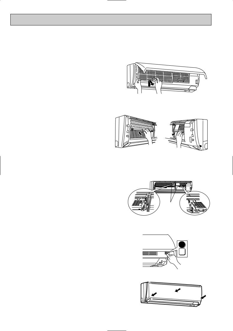
6. How to remove and install PLASMA DEODORIZING / AIR PURIFYING filter units
If PLASMA/WASH lamp on the indoor unit blinks, clean the filters as soon as possible. The lamp will start blinking when accumulated operating time exceeds 330 hours.
<Remove>
(1)Switch the indoor unit OFF with the remote controller and disconnect the power supply plug and/ or turn OFF the breaker.
NOTE: Otherwise, you may get injured since PLASMA DEODORIZING/AIR PURIFYING filter units are charged with high voltage.
(2)Hold the knobs on both sides of the front panel and lift the panel up until its level.
(3)Remove the anti-mold air filter.(See Figure 1.)
(4)Remove PLASMA DEODORIZING/AIR PURIFYING filter units. (See Figure 2.)
Figure 1.
Figure 2.
<Install>
Install PLASMA DEODORIZING/AIR PURIFYING filter units by following the removal procedure in reverse.
(1)Insert the top of PLASMA DEODORIZING/AIR PURIFYING filter units into the aperture in the plasma element holder.
(See Figure 3.)
(2)Push in PLASMA DEODORIZING/AIR PURIFYING filter units until they click into place.
•The front panel does not close if PLASMA DEODORIZING/AIR PURIFYING filter units are not installed properly.
(3)Install the anti-mold air filter.
(4)Connect the power supply plug and/ or turn ON the breaker.
(5)Press WASH reset switch. A short “beep” is heard and the blinks of PLASMA/WASH lamp will be cancelled. Make sure PLASMA/ WASH lamp is not blinking at the start of operation next time.
(See Figure 4.)
(6)Hold both sides of the front panel and close the front panel.
(7)Press the 3 positions on the front panel as indicated by the arrows.(See Figure 5.)
NOTE:
Install PLASMA DEODORIZING/AIR PURIFYING filter units only when they are completely dry. If the filter unit remains wet, PLASMA/WASH lamp may blink and the plasma function may be disabled.(When PLASMA DEODORIZING/AIR PURIFYING filter units are cleaned.)
Figure 3.
Figure 4.
Plasma element holder
E.O.
SW
WASH reset
Figure 5.
12
 Loading...