


This Servise Manual OB207 deals with MSH-07/09/12/18/24NV-E1,
MUH-07/09/12/18/24NV-E1, MSH-18NV-E2, and MUH-18NV-E2 in
OB176 REVISED EDITION-A issued in July in1997.
Therefore, please refer to OB207, not to OB176 REVISED
EDITION-A, for the above models.
SPLIT-TYPE,HEAT PUMP AIR CONDITIONERS
No. OB207
SERVICE MANUAL
Wireless type Models
MSH-07NV - MSH-09NV - MSH-12NV - MSH-18NV - MSH-24NV - MSH-07NV - MSH-09NV - MSH-12NV - MSH-18NV - MSH-24NV - MSH-18NV -
E1 (WH)
E1 (WH)
E1 (WH)
E1 (WH)
E1 (WH)
E2 (WH)
E2 (WH)
E2 (WH)
E2 (WH)
E2 (WH)
E3 (WH)
·MUH-07NV - E1
·MUH-09NV - E1
·MUH-12NV - E1
·MUH-18NV - E1
·MUH-24NV - E1
·MUH-07NV - E2
·MUH-09NV - E2
·MUH-12NV - E2
·MUH-18NV - E2
·MUH-24NV - E2
·MUH-18NV - E3
CONTENTS
MSH-18NV - E1 MSH-18NV - E2 MSH-18NV - E3
1.TECHNICAL CHANGES ····································2
2.PART NAMES AND FUNCTIONS······················3
3.SPECIFICATION·················································6
4.OUTLINES AND DIMENSIONS ······················ 11
5.WIRING DIAGRAM ··········································15
6.REFRIGERANT SYSTEM DIAGRAM ··············24
7.PERFORMANCE CURVES ······························29
8.MICROPROCESSOR CONTROL ····················33
9.SERVICE FUNCTIONS ····································44
10.TROUBLESHOOTING······································47
11.DISASSEMBLY INSTRUCTIONS·····················60
12.PARTS LIST······················································70
13.OPTIONAL PARTS ····································BACK
Refer to the Service Manual OB185 when MSH-07/09/12NV- E1 , MSH-07/09/12/18NV- E2 , and MSH-18NV- E3 are connected with MXZ-32NV- E1 as multi system units.
1 
 TECHNICAL CHANGES
MSH-17NV - E1 MSH-07NV - E2
1. Indoor electronic control P.C.board has changed.
However, it is compatible between E1 and E2 models. 2. Auto restart function is added.
MSH-09NV - E1 MSH-09NV - E2
1. Indoor electronic control P.C.board has changed.
However, it is compatible between E1 and E2 models. 2. Auto restart function is added.
MSH-12NV - E1 MSH-12NV - E2
1. Indoor electronic control P.C.board has changed.
However, it is compatible between E1 and E2 models. 2. Auto restart function is added.
MSH-18NV - E2 MSH-18NV - E3
1. Indoor electronic control P.C.board has changed.
However, it is compatible between E2 and E3 models. 2. Auto restart function is added.
MSH-24NV - E1 MSH-24NV - E2
1. Indoor electronic control P.C.board has changed.
However, it is compatible between E1 and E2 models. 2. Auto restart function is added.
2
2 
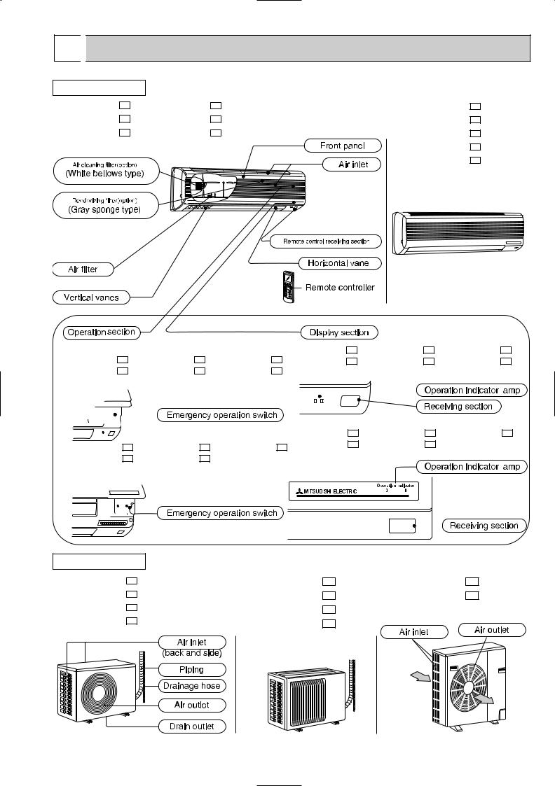
 PART NAMES AND FUNCTIONS
INDOOR UNIT
MSH-07NV - E1 MSH-09NV - E1 MSH-12NV - E1
MSH-07NV - E2 MSH-09NV - E2 MSH-12NV - E2
MSH-18NV - E1 MSH-24NV - E1 MSH-18NV - E2 MSH-24NV - E2 MSH-18NV - E3
(When the front panel is open) |
|
|
MSH-07NV |
- E1 |
MSH-09NV |
- E1 |
MSH-12NV |
- E1 |
|||||||||||||||||||
MSH-07NV |
- E1 |
|
MSH-09NV |
- E1 |
MSH-12NV |
- E1 |
MSH-07NV |
- E2 |
MSH-09NV |
- E2 |
MSH-12NV |
- E2 |
|||||||||||||||
MSH-07NV |
- E2 |
|
MSH-09NV |
- E2 |
MSH-12NV |
- E2 |
|
|
|
|
|
|
|
|
|
|
|
|
|
|
|||||||
|
|
|
|
|
|
|
|
|
|
|
|
|
|
|
|
|
|
|
|
|
|
|
|
|
|
|
|
|
|
|
|
|
|
|
|
|
|
|
|
|
|
|
|
|
|
|
|
|
|
|
|
|
|
|
|
|
|
|
|
|
|
|
|
|
|
|
|
|
|
|
|
|
|
|
|
|
|
|
|
|
|
|
|
|
|
|
|
|
|
|
|
|
|
|
|
|
|
|
|
|
|
|
|
|
|
|
|
|
|
|
|
|
|
|
|
|
|
|
|
|
|
|
|
|
|
|
|
|
|
|
|
|
|
|
|
|
|
|
|
|
|
|
|
|
|
|
|
|
|
|
|
|
|
|
|
|
|
|
|
|
|
|
|
|
|
|
|
|
|
|
|
|
|
|
|
|
|
|
|
|
|
|
|
|
|
|
|
|
|
|
|
|
|
|
|
|
|
|
|
|
|
|
|
|
MSH-18NV |
- E1 |
MSH-24NV |
- E1 |
MSH-18NV - E2 |
|||||||||||
MSH-18NV |
- E1 |
MSH-24NV |
- E1 |
MSH-18NV - E2 MSH-24NV |
- E2 |
MSH-18NV |
- E3 |
|
|
|||||||||||||||
MSH-24NV |
- E2 |
MSH-18NV |
- E3 |
|
|
|
|
|
|
|
|
|
|
|
|
|
|
|
|
|||||
|
|
|
|
|
|
|
|
|
|
|
|
|
|
|
|
|
|
|
|
|
|
|
|
|
|
|
|
|
|
|
|
|
|
|
|
|
|
|
|
|
|
|
|
|
|
|
|
|
|
|
|
|
|
|
|
|
|
|
|
|
|
|
|
|
|
|
|
|
|
|
|
|
|
|
|
|
|
|
|
|
|
|
|
|
|
|
|
|
|
|
|
|
|
|
|
|
|
|
|
|
|
|
|
|
|
|
|
|
|
|
|
|
|
|
|
|
|
|
|
|
|
|
|
|
|
|
|
|
|
|
|
|
|
|
|
|
|
|
|
|
|
|
|
|
|
|
|
|
|
|
|
|
|
|
|
|
|
|
|
|
|
|
|
|
|
|
|
|
|
|
|
|
|
|
|
|
|
|
|
|
|
|
|
|
|
|
|
|
|
|
|
|
|
|
|
|
|
|
|
|
|
|
|
|
|
|
|
|
|
|
|
|
|
|
|
|
|
|
|
|
|
|
|
|
|
|
|
|
|
|
|
|
|
|
|
|
|
|
|
|
|
|
|
|
|
|
|
|
|
|
|
|
|
|
|
|
|
|
|
|
|
|
|
|
|
|
|
|
|
|
|
|
|
|
|
|
|
|
|
|
|
|
|
|
|
|
|
|
|
|
|
|
|
|
|
|
|
|
|
OUTDOOR UNIT
MUH-07NV - E1 MUH-09NV - E1 MUH-07NV - E2 MUH-09NV - E2
MUH-12NV - E1 |
MUH-24NV |
- E1 |
|
MUH-18NV - E1 |
MUH-24NV |
- E2 |
|
MUH-18NV |
- E2 |
|
|
MUH-18NV |
- E3 |
|
|
3
MSH-07NV - E1 MSH-09NV - E1 MSH-12NV - E1 MSH-18NV - E1 MSH-18NV - E2
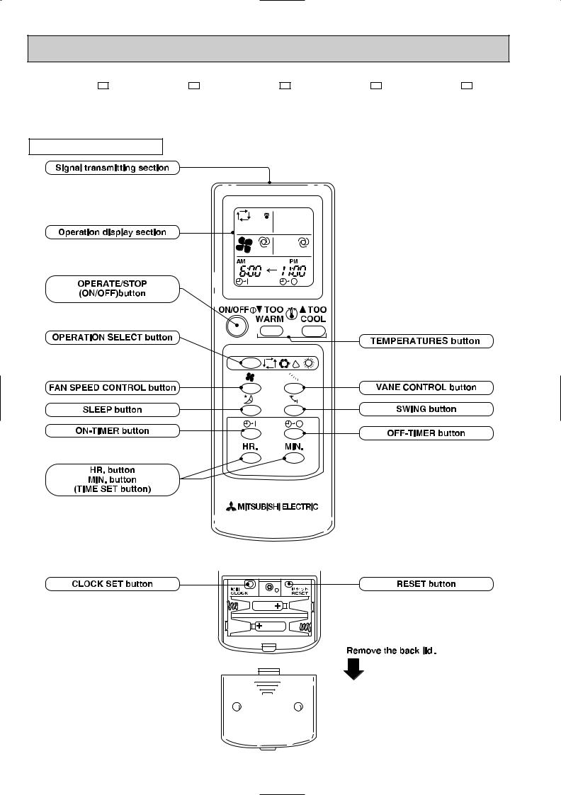
REMOTE CONTROLLER
4
|
|
|
|
|
|
|
|
|
|
|
|
|
|
|
|
|
|
|
|
|
|
|
|
|
|
|
|
|
|
|
|
|
|
|
|
|
|
|
|
|
|
|
|
|
|
|
|
|
MSH-07NV - E1 (Serial number 7000201T~) |
MSH-09NV |
|
|
- E1 (Serial number 7000201T~) |
||||||||||||||||||||||||||||||||||||||||||||
MSH-12NV - E1 |
|
(Serial number 7000001T~) |
MSH-24NV |
|
|
- E1 |
|
|
|
|
|
|
|
|
|
|
|
|
|
|
|
|
||||||||||||||||||||||||||
MSH-07NV - E2 |
|
|
|
|
|
|
|
MSH-09NV - E2 |
|
|
|
|
|
|
|
|
|
|
|
|
|
|
|
|
||||||||||||||||||||||||
MSH-12NV |
|
- E2 |
|
|
|
|
|
|
|
MSH-18NV |
|
|
- E2 |
(Serial number 7000001T~) |
||||||||||||||||||||||||||||||||||
MSH-24NV |
|
- E2 |
|
|
|
|
|
|
|
MSH-18NV |
|
|
- E3 |
|
|
|
|
|
|
|
|
|
|
|
|
|
|
|
|
|||||||||||||||||||
|
|
|
|
|
|
|
|
|
|
|
|
|
|
|
|
|
|
|
|
|
|
|
|
|
|
|
|
|
|
|
|
|
|
|
|
|
|
|
|
|
|
|
|
|
|
|
|
|
|
|
|
|
|
|
|
|
|
|
|
|
|
|
|
|
|
|
|
|
|
|
|
|
|
|
|
|
|
|
|
|
|
|
|
|
|
|
|
|
|
|
|
|
|
|
|
|
|
|
|
|
|
|
|
|
|
|
|
|
|
|
|
|
|
|
|
|
|
|
|
|
|
|
|
|
|
|
|
|
|
|
|
|
|
|
|
|
|
|
|
|
|
|
|
|
|
|
|
|
|
|
|
|
|
|
|
|
|
|
|
|
|
|
|
|
|
|
|
|
|
|
|
|
|
|
|
|
|
|
|
|
|
|
|
|
|
|
|
|
|
|
|
|
|
|
|
|
|
|
|
|
|
|
|
|
|
|
|
|
|
|
|
|
|
|
|
|
|
|
|
|
|
|
|
|
|
|
|
|
|
|
|
|
|
|
|
|
|
|
|
|
|
|
|
|
|
|
|
|
|
|
|
|
|
|
|
|
|
|
|
|
|
|
|
|
|
|
|
|
|
|
|
|
|
|
|
|
|
|
|
|
|
|
|
|
|
|
|
|
|
|
|
|
|
|
|
|
|
|
|
|
|
|
|
|
|
|
|
|
|
|
|
|
|
|
|
|
|
|
|
|
|
|
|
|
|
|
|
|
|
|
|
|
|
|
|
|
|
|
|
|
|
|
|
|
|
|
|
|
|
|
|
|
|
|
|
|
|
|
|
|
|
|
|
|
|
|
|
|
|
|
|
|
|
|
|
|
|
|
|
|
|
|
|
|
|
|
|
|
|
|
|
|
|
|
|
|
|
|
|
|
|
|
|
|
|
|
|
|
|
|
|
|
|
|
|
|
|
|
|
|
|
|
|
|
|
|
|
|
|
|
|
|
|
|
|
|
|
|
|
|
|
|
|
|
|
|
|
|
|
|
|
|
|
|
|
|
|
|
|
|
|
|
|
|
|
|
|
|
|
|
|
|
|
|
|
|
|
|
|
|
|
|
|
|
|
|
|
|
|
|
|
|
|
|
|
|
|
|
|
|
|
|
|
|
|
|
|
|
|
|
|
|
|
|
|
|
|
|
|
|
|
|
|
|
|
|
|
|
|
|
|
|
|
|
|
|
|
|
|
|
|
|
|
|
|
|
|
|
|
|
|
|
|
|
|
|
|
|
|
|
|
|
|
|
|
|
|
|
|
|
|
|
|
|
|
|
|
|
|
|
|
|
|
|
|
|
|
|
|
|
|
|
|
|
|
|
|
|
|
|
|
|
|
|
|
|
|
|
|
|
|
|
|
|
|
|
|
|
|
|
|
|
|
|
|
|
|
|
|
|
|
|
|
|
|
|
|
|
|
|
|
|
|
|
|
|
|
|
|
|
|
|
|
|
|
|
|
|
|
|
|
|
|
|
|
|
|
|
|
|
|
|
|
|
|
|
|
|
|
|
|
|
|
|
|
|
|
|
|
|
|
|
|
|
|
|
|
|
|
|
|
|
|
|
|
|
|
|
|
|
|
|
|
|
|
|
|
|
|
|
|
|
|
|
|
|
|
|
|
|
|
|
|
|
|
|
|
|
|
|
|
|
|
|
|
|
|
|
|
|
|
|
|
|
|
|
|
|
|
|
|
|
|
|
|
|
|
|
|
|
|
|
|
|
|
|
|
|
|
|
|
|
|
|
|
|
|
|
|
|
|
|
|
|
|
|
|
|
|
|
|
|
|
|
|
|
|
|
|
|
|
|
|
|
|
|
|
|
|
|
|
|
|
|
|
|
|
|
|
|
|
|
|
|
|
|
|
|
|
|
|
|
|
|
|
|
|
|
|
|
|
|
|
|
|
|
|
|
|
|
|
|
|
|
|
|
|
|
|
|
|
|
|
|
|
|
|
|
|
|
|
|
|
|
|
|
|
|
|
|
|
|
|
|
|
|
|
|
|
|
|
|
|
|
|
|
|
|
|
|
|
|
|
|
|
|
|
|
|
|
|
|
|
|
|
|
|
|
|
|
|
|
|
|
|
|
|
|
|
|
|
|
|
|
|
|
|
|
|
|
|
|
|
|
|
|
|
|
|
|
|
|
|
|
|
|
|
|
|
|
|
|
|
|
|
|
|
|
|
|
|
|
|
|
|
|
|
|
|
|
|
|
|
|
|
|
|
|
|
|
|
|
|
|
|
|
|
|
|
|
|
|
|
|
|
|
|
|
|
|
|
|
|
|
|
|
|
|
|
|
|
|
|
|
|
|
|
|
|
|
|
|
|
|
|
|
|
|
|
|
|
|
|
|
|
|
|
|
|
|
|
|
|
|
|
|
|
|
|
|
|
|
|
|
|
|
|
|
|
|
|
|
|
|
|
|
|
|
|
|
|
|
|
|
|
|
|
|
|
|
|
|
|
|
|
|
|
|
|
|
|
|
|
|
|
|
|
|
|
|
|
|
|
|
|
|
|
|
|
|
|
|
|
|
|
|
|
|
|
|
|
|
|
|
|
|
|
|
|
|
|
|
|
|
|
|
|
|
|
|
|
|
|
|
|
|
|
|
|
|
|
|
|
|
|
|
|
|
|
|
|
|
|
|
|
|
|
|
|
|
|
|
|
|
|
|
|
|
|
|
|
|
|
|
|
|
|
|
|
|
|
|
|
|
|
|
|
|
|
|
|
|
|
|
|
|
|
|
|
|
|
|
|
|
|
|
|
|
|
|
|
|
|
|
|
|
|
|
|
|
|
|
|
|
|
|
|
|
|
|
|
|
|
|
|
|
|
|
|
|
|
|
|
|
|
|
|
|
|
|
|
|
|
|
|
|
|
|
|
|
|
|
|
|
|
|
|
|
|
|
|
|
|
|
|
|
|
|
|
|
|
|
|
|
|
|
|
|
|
|
|
|
|
|
|
|
|
|
|
|
|
|
|
|
|
|
|
|
|
|
|
|
|
|
|
|
|
|
|
|
|
|
|
|
|
|
|
|
|
|
|
|
|
|
|
|
|
|
|
|
|
|
|
|
|
|
|
|
|
|
|
|
|
|
|
|
|
|
|
|
|
|
|
|
|
|
|
|
|
|
|
|
|
|
|
|
|
|
|
|
|
|
|
|
|
|
|
|
|
|
|
|
|
|
|
|
|
|
|
|
|
|
|
|
|
|
|
|
|
|
|
|
|
|
|
|
|
|
|
|
|
|
|
|
|
|
|
|
|
|
|
|
|
|
|
|
|
|
|
|
|
|
|
|
|
|
|
|
|
|
|
|
|
|
|
|
|
|
|
|
|
|
|
|
|
|
|
|
|
|
|
|
|
|
|
|
|
|
|
|
|
|
|
|
|
|
|
|
|
|
|
|
|
|
|
|
|
|
|
|
|
|
|
|
|
|
|
|
|
|
|
|
|
|
|
|
|
|
|
|
|
|
|
|
|
|
|
|
|
|
|
|
|
|
|
|
|
|
|
|
|
|
|
|
|
|
|
|
|
|
|
|
|
|
|
|
|
|
|
|
|
|
|
|
|
|
|
|
|
|
|
|
|
|
|
|
|
|
|
|
|
|
|
|
|
|
|
|
|
|
|
|
|
|
|
|
|
|
|
|
|
|
|
|
|
|
|
|
|
|
|
|
|
|
|
|
|
|
|
|
|
|
|
|
|
|
|
|
|
|
|
|
|
|
|
|
|
|
|
|
|
|
|
|
|
|
|
|
|
|
|
|
|
|
|
|
|
|
|
|
|
|
|
|
|
|
|
|
|
|
|
|
|
|
|
|
|
|
|
|
|
|
|
|
|
|
|
|
|
|
|
|
|
|
|
|
|
|
|
|
|
|
|
|
|
|
|
|
|
|
|
|
|
|
|
|
|
|
|
|
|
|
|
|
|
|
|
|
|
|
|
|
|
|
|
|
|
|
|
|
|
|
|
|
|
|
|
|
|
|
|
|
|
|
|
|
|
|
|
|
|
|
|
|
|
|
|
|
|
|
|
|
|
|
|
|
|
|
|
|
|
|
|
|
|
|
|
|
|
|
|
|
|
|
|
|
|
|
|
|
|
|
|
|
|
|
|
|
|
|
|
|
|
|
|
|
|
|
|
|
|
|
|
|
|
|
|
|
|
|
|
|
|
|
|
|
|
|
|
|
|
|
|
|
|
|
|
|
|
|
|
|
|
|
|
|
|
|
|
|
|
|
|
|
|
|
|
|
|
|
|
|
|
|
|
|
|
|
|
|
|
|
|
|
|
|
|
|
|
|
|
|
|
|
|
|
|
|
|
|
|
|
|
|
|
|
|
|
|
|
|
|
|
|
|
|
|
|
|
|
|
|
|
|
|
|
|
|
|
5

3 |
|
|
SPECIFICATION |
|
|
|
|
|
|
|
|
|
|
|
|
|||
|
|
|
|
|
|
|
|
|
|
|
|
|
|
|
|
|
|
|
|
|
|
|
|
|
|
|
|
|
|
|
|
|
|
|
|
|
|
|
|
|
|
|
Model |
|
|
MSH-07NV - |
|
|
|
MSH-09NV - |
|
|
|
|
||
|
|
|
|
|
|
|
E1 |
E2 |
|
|
E1 |
E2 |
|
|||||
|
|
|
|
|
|
|
|
|
|
|
|
|
|
|
|
|
|
|
|
|
|
|
|
Function |
|
|
Cooling |
|
Heating |
Cooling |
|
|
Heating |
||||
|
|
|
|
|
|
|
|
|
|
|
|
|
|
|
|
|
|
|
|
|
|
|
|
Power supply |
|
|
Single phase,220-240V,50Hz |
Single phase,220-240V,50Hz |
|||||||||
|
|
|
|
Capacity |
|
kW |
2.2 |
|
2.5 |
|
2.5 |
|
3.1 |
|
||||
|
Capacity |
Dehumidification |
|
R/h |
0.8 |
|
— |
1.1 |
|
|
— |
|||||||
|
|
|
|
Air flow |
|
K /h |
INDOOR 492 OUTDOOR 1620 |
INDOOR 492 OUTDOOR 1620 |
||||||||||
|
|
|
|
Power outlet |
|
A |
10 |
|
|
|
10 |
|
|
|
|
|||
|
|
|
|
Running current |
|
A |
3.30-3.20 |
|
3.15-3.05 |
4.10-4.00 |
|
4.30-4.10 |
||||||
|
|
|
|
Power input |
|
W |
710-750 |
|
680-720 |
880-920 |
|
920-940 |
|
|||||
|
|
|
|
Auxiliary heater |
|
A(kW) |
— |
|
— |
— |
|
|
— |
|||||
Electrical data |
Power factor |
|
% |
98-98 |
|
|
|
98-96 |
|
97-96 |
|
|||||||
|
|
|
|
Starting current |
|
A |
25 |
|
|
|
25 |
|
|
|
|
|||
|
|
|
|
Compressor motor current |
A |
2.80-2.70 |
|
2.65-2.55 |
3.60-3.50 |
|
3.80-3.60 |
|||||||
|
|
|
|
Fan motor current |
|
A |
INDOOR 0.17 OUTDOOR 0.33 |
INDOOR 0.17 OUTDOOR 0.33 |
||||||||||
Coefficient of performance(C.O.P) |
|
|
3.10-2.93 |
|
3.68-3.47 |
2.84-2.72 |
|
3.37-3.30 |
||||||||||
|
|
|
|
Model |
|
|
RH-135VGHT |
RH-174VGHT |
||||||||||
Compressor |
Output |
|
W |
650 |
|
|
|
800 |
|
|
|
|
||||||
|
|
|
|
|
|
|
|
|
|
|
|
|
|
|
|
|
||
|
|
|
|
Winding resistance(at20:) |
" |
C-R4.17 C-S5.75 |
C-R3.26 C-S5.82 |
|||||||||||
|
Indoor |
Model |
|
|
RC4V19-AA |
RC4V19-AA |
||||||||||||
|
fan motor |
|
|
|
|
|
|
|
|
|
|
|
|
|
||||
|
Winding resistance(at20:) |
" |
WHT-BLK292 BLK-RED324 |
WHT-BLK292 BLK-RED324 |
||||||||||||||
|
Outdoor |
Model |
|
|
RA6V29-CB |
RA6V29-CB |
||||||||||||
|
fan motor |
Winding resistance(at20:) |
" |
WHT-BLK218.0 BLK-RED423.7 |
WHT-BLK218.0 BLK-RED423.7 |
|||||||||||||
|
|
|
|
|
|
Width |
mm |
815 |
|
|
|
815 |
|
|
|
|
||
|
|
|
|
Indoor unit |
Height |
mm |
275 |
|
|
|
275 |
|
|
|
|
|||
Dimensions |
|
|
Depth |
mm |
183 |
|
|
|
183 |
|
|
|
|
|||||
|
|
|
|
|
|
Width |
mm |
780 |
|
|
|
780 |
|
|
|
|
||
|
|
|
|
Outdoor unit |
Height |
mm |
540 |
|
|
|
540 |
|
|
|
|
|||
|
|
|
|
|
|
Depth |
mm |
255 |
|
|
|
255 |
|
|
|
|
||
|
Weight |
Indoor unit |
|
kg |
8 |
|
|
|
8 |
|
|
|
|
|||||
|
|
|
|
|
|
|
|
|
|
|
|
|
|
|
|
|||
|
Outdoor unit |
|
kg |
34 |
|
|
|
34 |
|
|
|
|
||||||
|
|
|
|
|
|
|
|
|
|
|
|
|||||||
|
|
|
|
|
|
|
|
|
|
|
|
|
|
|
|
|
||
|
|
|
|
Air direction |
|
|
5 |
|
|
|
5 |
|
|
|
|
|||
|
|
|
|
|
|
|
|
|
|
|
|
|
|
|
|
|
|
|
|
|
|
|
Sound level |
Indoor unit |
dB |
37 |
|
|
|
37 |
|
|
|
|
|||
|
|
|
|
(Hi) |
Outdoor unit |
dB |
47 |
|
|
|
48 |
|
|
|
|
|||
|
|
|
|
Fan speed |
Indoor unit |
rpm |
1,100 |
|
|
|
1,100 |
|
|
|
||||
|
|
|
|
(Hi) |
Outdoor unit |
rpm |
790-820 |
|
|
790-820 |
|
|
||||||
Special remarks |
Fan speed |
Indoor unit |
|
4 |
|
|
|
4 |
|
|
|
|
||||||
|
|
|
|
|
|
|
|
|
|
|
|
|
|
|
|
|
|
|
|
|
|
|
regulator |
Outdoor unit |
|
1 |
|
|
|
1 |
|
|
|
|
|||
|
|
|
|
|
|
|
|
|
|
|
|
|
|
|
|
|
|
|
|
|
|
|
Refrigerant filling capacity(R-22) |
kg |
0.85 |
|
|
|
0.85 |
|
|
|
|
||||
|
|
|
|
|
|
|
|
|
|
|
|
|
|
|
|
|
|
|
|
|
|
|
|
|
RT11(at25:) |
k" |
10 |
|
|
|
10 |
|
|
|
|
||
|
|
|
|
Thermistor |
RT12(at25:) |
k" |
10 |
|
|
|
10 |
|
|
|
|
|||
|
|
|
|
|
|
RT61(at0:) |
k" |
33.18 |
|
|
|
33.18 |
|
|
|
|||
NOTE:Test conditions |
|
|
|
|
|
|
|
|
|
|
|
|
|
|
||||
|
Cooling : Indoor |
DB27°C / WB19°C |
|
|
|
|
|
|
|
|
|
|
|
|
||||
|
|
|
Outdoor DB35°C / WB24°C |
|
|
|
|
|
|
|
|
|
|
|
|
|||
|
Heating : Indoor |
DB20°C /WB15.5°C |
|
|
|
|
|
|
|
|
|
|
|
|
||||
|
|
|
Outdoor DB 7°C / WB 6°C |
|
|
|
|
|
|
|
|
|
|
|
|
|||
6

|
|
|
|
|
|
|
|
|
|
|
|
|
|
|
|
|
|
|
|
|
|
|
|
|
|
|
|
|
|
|
|
|
|
|
|
|
|
Model |
|
|
MSH-12NV - |
|
|
|
|
MSH-18NV - |
|
|
|
|
|
|
|
|
|
|
|
E1 |
|
E2 |
|
|
E1 |
|
E2 |
E3 |
|
||||
|
|
|
|
|
|
|
|
|
|
|
|
|
|
|
|
|
|
|
|
Function |
|
|
Cooling |
|
Heating |
Cooling |
|
Heating |
|
||||||
|
|
|
|
|
|
|
|
|
|
|
|
|
|
|
|
|
|
|
|
Power supply |
|
|
Single phase,220-240V,50Hz |
Single phase,220-240V,50Hz |
|
||||||||||
|
Capacity |
|
kW |
3.4 |
|
4.0 |
|
5.1 |
|
5.4 |
|
|
|||||
Capacity |
Dehumidification |
|
R/h |
1.6 |
|
— |
2.5 |
|
|
|
— |
|
|||||
|
Air flow |
|
K /h |
INDOOR 558 OUTDOOR 2130-2244 |
INDOOR 756 OUTDOOR 2142 |
|
|||||||||||
|
Power outlet |
|
A |
10 |
|
|
|
|
15 |
|
|
|
|
|
|||
|
Running current |
|
A |
5.75-5.90 |
|
5.95-6.10 |
9.4-9.2 |
|
9.2-9.0 |
|
|||||||
|
Power input |
|
W |
1220-1300 |
|
1260-1350 |
2030-2120 |
|
1980-2070 |
|
|||||||
|
Auxiliary heater |
|
A(kW) |
— |
|
— |
— |
|
|
|
— |
|
|||||
Electrical data |
Power factor |
|
% |
96-92 |
|
96-92 |
|
98-96 |
|
98-96 |
|
|
|||||
|
Starting current |
|
A |
35 |
|
|
|
|
52-58 |
|
|
|
|
||||
|
Compressor motor current |
A |
5.21-5.36 |
|
5.41-5.56 |
8.76-8.56 |
|
8.56-8.36 |
|
||||||||
|
Fan motor current |
|
A |
INDOOR 0.17 OUTDOOR 0.37 |
INDOOR 0.25 OUTDOOR 0.39 |
|
|||||||||||
Coefficient of performance(C.O.P) |
|
|
2.78-2.61 |
|
3.17-2.96 |
2.51-2.41 |
|
2.73-2.61 |
|
||||||||
|
Model |
|
|
RH-231VHAT |
NH-36VMDT |
|
|||||||||||
Compressor |
|
|
|
|
|
|
|
|
|
|
|
|
|
|
|
||
Output |
|
W |
1100 |
|
|
|
|
1700 |
|
|
|
|
|||||
|
|
|
|
|
|
|
|
|
|
|
|
|
|
|
|
||
|
Winding resistance(at20:) |
" |
C-R2.1 C-S3.9 |
C-R1.2 C-S2.7 |
|
||||||||||||
Indoor |
Model |
|
|
RC4V19-AA |
RA4V27-EA |
|
|||||||||||
fan motor |
Winding resistance(at20:) |
" |
WHT-BLK292 BLK-RED324 |
WHT-BLK183.8 BLK-RED250.5 |
|
||||||||||||
Outdoor |
Model |
|
|
RA6V40-EC or EE |
RA6V50-OD or OF |
|
|||||||||||
fan motor |
Winding resistance(at20:) |
" |
WHT-BLK130 BLK-RED134.6 |
WHT-BLK116.4 BLK-RED111.0 |
|
||||||||||||
|
|
|
Width |
mm |
815 |
|
|
|
|
1015 |
|
|
|
|
|||
|
Indoor unit |
Height |
mm |
275 |
|
|
|
|
320 |
|
|
|
|
|
|||
Dimensions |
|
|
Depth |
mm |
183 |
|
|
|
|
190 |
|
|
|
|
|
||
|
|
Width |
mm |
850 |
|
|
|
|
850 |
|
|
|
|
|
|||
|
|
|
|
|
|
|
|
|
|
|
|
||||||
|
Outdoor unit |
Height |
mm |
605 |
|
|
|
|
605 |
|
|
|
|
|
|||
|
|
|
Depth |
mm |
290 |
|
|
|
|
290 |
|
|
|
|
|
||
Weight |
Indoor unit |
|
kg |
8 |
|
|
|
|
14 |
|
|
|
|
|
|||
Outdoor unit |
|
kg |
43 |
|
|
|
|
59 |
|
|
|
|
|
||||
|
|
|
|
|
|
|
|
|
|
|
|||||||
|
|
|
|
|
|
|
|
|
|
|
|
|
|
|
|
|
|
|
Air direction |
|
|
5 |
|
|
|
|
5 |
|
|
|
|
|
|||
|
|
|
|
|
|
|
|
|
|
|
|
|
|
|
|
|
|
|
Sound level |
Indoor unit |
dB |
42 |
|
|
|
|
42 |
|
|
|
|
|
|||
|
(Hi) |
Outdoor unit |
dB |
50 |
|
|
|
|
52 |
|
|
|
|
|
|||
|
Fan speed |
Indoor unit |
rpm |
1230 |
|
|
|
|
1180 |
|
|
|
|
||||
|
|
|
|
|
|
|
|
|
|
|
|
|
|
|
|
||
|
(Hi) |
Outdoor unit |
rpm |
780-820 |
|
|
|
810-845 |
|
|
|
|
|||||
Special remarks |
|
|
|
|
|
|
|
|
|
|
|
|
|
|
|
|
|
Fan speed |
Indoor unit |
|
4 |
|
|
|
|
4 |
|
|
|
|
|
||||
|
|
|
|
|
|
|
|
|
|
|
|
|
|
|
|
|
|
|
regulator |
Outdoor unit |
|
1 |
|
|
|
|
1 |
|
|
|
|
|
|||
|
|
|
|
|
|
|
|
|
|
|
|
|
|
|
|
|
|
|
Refrigerant filling capacity(R-22) |
kg |
1.15 |
|
|
|
|
1.8 |
|
|
|
|
|
||||
|
|
|
|
|
|
|
|
|
|
|
|
|
|
|
|
|
|
|
|
|
RT11(at25:) |
k" |
10 |
|
|
|
|
10 |
|
|
|
|
|
||
|
Thermistor |
RT12(at25:) |
k" |
10 |
|
|
|
|
10 |
|
|
|
|
|
|||
|
|
|
RT61(at0:) |
k" |
33.18 |
|
|
|
33.18 |
|
|
|
|
||||
NOTE:Test conditions |
|
|
|
|
|
|
|
|
|
|
|
|
|
|
|
|
|
Cooling : Indoor |
DB27°C / WB19°C |
|
|
|
|
|
|
|
|
|
|
|
|
|
|
||
Outdoor DB35°C / WB24°C |
|
|
|
|
|
|
|
|
|
|
|
|
|
|
|||
Heating : Indoor |
DB20°C /WB15°.5C |
|
|
|
|
|
|
|
|
|
|
|
|
|
|
||
Outdoor DB 7°C / WB 6°C |
|
|
|
|
|
|
|
|
|
|
|
|
|
|
|||
7

|
|
|
|
|
|
|
|
|
|
|
|
|
|
|
|
|
|
|
|
|
|
|
|
|
|
Model |
|
|
MSH-24NV - |
|
|
|
|
|
|
|
|
|
|
|
E1 |
|
E2 |
|
|||
|
|
|
|
|
|
|
|
|
|
|
|
|
Function |
|
|
Cooling |
|
|
|
|
Heating |
||
|
Power supply |
|
|
Single phase,220-240V,50Hz |
|||||||
|
Capacity |
|
kW |
6.0 |
|
6.2 |
|
||||
Capacity |
Dehumidification |
|
R/h |
3.1 |
|
|
|
— |
|||
|
Air flow |
|
|
K /h |
816 |
|
|
|
|
|
|
|
Power outlet |
|
A |
25 |
|
|
|
|
|
||
|
Running current |
|
A |
12.6-11.7 |
|
11.5-11.0 |
|||||
|
Power input |
|
W |
2720-2750 |
2470-2580 |
||||||
|
Auxiliary heater |
|
A(kW) |
— |
|
|
|
|
|
||
Electrical data |
Power factor |
|
% |
98 |
|
|
|
|
|
||
|
Starting current |
|
A |
59 |
|
|
|
|
|
||
|
Compressor motor current |
A |
11.73-10.83 |
10.63-10.13 |
|||||||
|
Fan motor current |
|
A |
INDOOR 0.29 OUTDOOR 0.58 |
|||||||
Coefficient of performance(C.O.P) |
|
|
2.21-2.18 |
|
2.51-2.40 |
|
|||||
|
Model |
|
|
|
NH-47VMDT |
||||||
Compressor |
|
|
|
|
|
|
|
|
|
|
|
Output |
|
|
W |
2200 |
|
|
|
|
|
||
|
|
|
|
|
|
|
|
|
|
||
|
Winding resistance(at20:) |
" |
C-R 0.96 C-S 2.07 |
||||||||
Indoor |
Model |
|
|
|
RA4V27-EC |
||||||
fan motor |
|
|
|
|
|
|
|
|
|
||
Winding resistance(at20:) |
" |
WHT-BLK183.8 BLK-RED250.5 |
|||||||||
Outdoor |
Model |
|
|
|
RA6V85-AA |
||||||
fan motor |
Winding resistance(at20:) |
" |
WHT-BLK62.7 BLK-YLW30.2 YLW-RED62.9 |
||||||||
|
|
|
Width |
mm |
1015 |
|
|
|
|
|
|
|
Indoor unit |
Height |
mm |
320 |
|
|
|
|
|
||
Dimensions |
|
|
Depth |
mm |
190 |
|
|
|
|
|
|
|
|
Width |
mm |
870 |
|
|
|
|
|
||
|
|
|
|
|
|
|
|
||||
|
Outdoor unit |
Height |
mm |
850 |
|
|
|
|
|
||
|
|
|
Depth |
mm |
295 |
|
|
|
|
|
|
Weight |
Indoor unit |
|
kg |
14 |
|
|
|
|
|
||
|
|
|
|
|
|
|
|
|
|
|
|
Outdoor unit |
|
kg |
72 |
|
|
|
|
|
|||
|
|
|
|
|
|
|
|||||
|
Air direction |
|
|
5 |
|
|
|
|
|
||
|
|
|
|
|
|
|
|
|
|
|
|
|
Sound level |
Indoor unit |
dB |
45 |
|
|
|
|
|
||
|
(Hi) |
|
Outdoor unit |
dB |
53 |
|
|
|
|
|
|
|
Fan speed |
Indoor unit |
rpm |
1,260 |
|
|
|
|
|||
Special remarks |
(Hi) |
|
Outdoor unit |
rpm |
720-750 |
|
|
|
|||
|
|
|
|
|
|
|
|
|
|
|
|
|
Fan speed |
Indoor unit |
|
4 |
|
|
|
|
|
||
|
|
|
|
|
|
|
|
|
|
|
|
|
regulator |
Outdoor unit |
|
2 |
|
|
|
|
|
||
|
|
|
|
|
|
|
|
|
|
|
|
|
Refrigerant filling capacity(R-22) |
kg |
2.4 |
|
|
|
|
|
|||
|
|
|
|
|
|
|
|
|
|
|
|
|
|
|
RT11(at25:) |
k" |
10 |
|
|
|
|
|
|
|
Thermistor |
RT12(at25:) |
k" |
10 |
|
|
|
|
|
||
|
|
|
RT61(at0:) |
k" |
33.18 |
|
|
|
|
||
NOTE:Test conditions |
|
|
|
|
|
|
|
|
|
|
|
Cooling : Indoor |
DB27°C / WB19°C |
|
|
|
|
|
|
|
|
||
|
Outdoor DB35°C / WB24°C |
|
|
|
|
|
|
|
|
||
Heating : Indoor |
DB20°C /WB15.5°C |
|
|
|
|
|
|
|
|
||
|
Outdoor DB 7°C / WB 6°C |
|
|
|
|
|
|
|
|
||
8
Refer to the Service Manual OB185 when MSH-07/09/12NV- E1 , MSH-07/09/12/18NV- E2 , and MSH-18NV- E3 |
are |
||||||
connected with MXZ-32NV- E1 as multi system units. |
|
|
|
|
|
|
|
|
Model |
|
MSH-07NV- E1 E2 (INDOOR UNIT) MSH-09NV- E1 E2 (INDOOR UNIT) |
||||
|
Function |
|
Cooling |
Heating |
Cooling |
Heating |
|
|
Power supply |
|
Single phase,220-240V,50Hz Single phase,220-240V,50Hz |
||||
|
Capacity |
kW |
— |
— |
— |
— |
|
Capacity |
Dehumidification |
R/h |
— |
— |
— |
— |
|
|
Air flow |
K /h |
492 |
|
|
492 |
|
|
Power outlet |
A |
10 |
|
|
10 |
|
|
Running current |
A |
0.17 |
|
|
0.17 |
|
|
Power input |
W |
35 |
|
|
35 |
|
|
Auxiliary heater |
A(kW) |
— |
|
|
— |
|
Electrical data |
Power factor |
% |
94-86 |
|
|
94-86 |
|
|
Starting current |
A |
— |
|
|
— |
|
|
Compressor motor current |
A |
— |
|
|
— |
|
|
Fan motor current |
A |
0.17 |
|
|
0.17 |
|
Coefficient of performance(C.O.P) |
|
— |
|
|
— |
|
|
|
Model |
|
— |
|
|
— |
|
Compressor |
Output |
W |
— |
|
|
— |
|
|
Winding resistance(at20:) |
" |
— |
|
|
— |
|
Indoor |
Model |
|
|
RC4V19-AA |
RC4V19-AA |
|
fan motor |
Winding resistance(at20:) |
" |
WHT-BLK292 BLK-RED324 WHT-BLK292 BLK-RED324 |
|||
Outdoor |
Model |
|
|
— |
— |
|
fan motor |
Winding resistance(at20:) |
" |
— |
— |
||
|
|
|
Width |
mm |
815 |
815 |
|
Indoor unit |
Height |
mm |
275 |
275 |
|
Dimensions |
|
|
Depth |
mm |
183 |
183 |
|
|
Width |
mm |
— |
— |
|
|
|
|
||||
|
Outdoor unit |
Height |
mm |
— |
— |
|
|
|
|
Depth |
mm |
— |
— |
Weight |
Indoor unit |
|
kg |
8 |
8 |
|
|
|
|
|
|
|
|
Outdoor unit |
|
kg |
— |
— |
||
|
|
|||||
|
Air direction |
|
|
5 |
5 |
|
|
|
|
|
|
|
|
|
Sound level |
Indoor unit |
dB |
37 |
37 |
|
|
(Hi) |
Outdoor unit |
dB |
— |
— |
|
|
Fan speed |
Indoor unit |
rpm |
1,100 |
1,100 |
|
Special remarks |
(Hi) |
Outdoor unit |
rpm |
— |
— |
|
|
|
|
|
|
|
|
|
Fan speed |
Indoor unit |
|
4 |
4 |
|
|
|
|
|
|
|
|
|
regulator |
Outdoor unit |
|
— |
— |
|
|
|
|
|
|
|
|
|
Refrigerant filling capacity(R-22) |
kg |
— |
— |
||
|
|
|
|
|
|
|
|
|
|
RT11(at25:) |
k" |
10 |
10 |
|
Thermistor |
RT12(at25:) |
k" |
10 |
10 |
|
|
|
|
RT61(at0:) |
k" |
— |
— |
NOTE:Test conditions |
|
|
|
Please refer to Service manual OB185 for capacity. |
||
Cooling : Indoor |
DB27°C / WB19°C |
|
|
|
||
Outdoor DB35°C / WB24°C |
|
|
|
|||
Heating : Indoor |
DB20°C /WB15.5°C |
|
|
|
||
Outdoor DB 7°C / WB 6°C |
|
|
|
|||
9
Refer to the Service Manual OB185 when MSH-07/09/12NV- E1 , MSH-07/09/12/18NV- E2 , and MSH-18NV- E3 are connected with MXZ-32NV- E1 as multi system units.
Model |
MSH-12NV- E1 E2 (INDOOR UNIT)MSH-18NV- E2 E3 (INDOOR UNIT) |
|||
Function |
Cooling |
Heating |
Cooling |
Heating |
Power supply |
Single phase,220-240V,50Hz Single phase,220-240V,50Hz |
|||
Capacity |
kW |
— |
— |
— |
— |
Capacity |
Dehumidification |
|
R/h |
— |
— |
|
|
|
Air flow |
|
K /h |
558 |
756 |
|
|
Power outlet |
|
A |
10 |
10 |
|
|
Running current |
|
A |
0.17 |
0.28 |
|
|
Power input |
|
W |
35 |
60 |
|
|
Auxiliary heater |
|
A(kW) |
— |
— |
Electrical data |
Power factor |
|
% |
94-86 |
97-89 |
|
|
|
Starting current |
|
A |
— |
— |
|
|
|
|
|
|
|
|
|
Compressor motor current |
A |
— |
— |
|
|
|
|
|
|
|
|
|
|
Fan motor current |
|
A |
0.17 |
0.25 |
Coefficient of performance(C.O.P) |
|
|
— |
— |
||
|
|
Model |
|
|
— |
— |
Compressor |
|
Output |
|
W |
— |
— |
|
|
Winding resistance(at20:) |
" |
— |
— |
|
Indoor |
|
Model |
|
|
RA4V19-AA |
RA4V27-EA |
fan motor |
|
|
|
|
|
|
|
Winding resistance(at20:) |
" |
WHT-BLK292 BLK-RED324 WHT-BLK184 BLK-RED251 |
|||
Outdoor |
|
Model |
|
|
— |
— |
fan motor |
|
Winding resistance(at20:) |
" |
— |
— |
|
|
|
|
Width |
mm |
815 |
1015 |
|
|
Indoor unit |
Height |
mm |
275 |
320 |
Dimensions |
|
|
Depth |
mm |
183 |
190 |
|
|
Width |
mm |
— |
— |
|
|
|
|
||||
|
|
Outdoor unit |
Height |
mm |
— |
— |
|
|
|
Depth |
mm |
— |
— |
Weight |
|
Indoor unit |
|
kg |
8 |
14 |
|
|
|
|
|
|
|
|
Outdoor unit |
|
kg |
— |
— |
|
|
|
|
||||
|
|
|
|
|
|
|
|
|
Air direction |
|
|
5 |
5 |
|
|
|
|
|
|
|
|
|
Sound level |
Indoor unit |
dB |
42 |
42 |
|
|
|
|
|
|
|
|
|
(Hi) |
Outdoor unit |
dB |
— |
— |
|
|
|
|
|
|
|
|
|
Fan speed |
Indoor unit |
rpm |
1,230 |
1,180 |
Special remarks |
|
(Hi) |
Outdoor unit |
rpm |
— |
— |
|
|
Fan speed |
Indoor unit |
|
4 |
4 |
|
|
regulator |
Outdoor unit |
|
— |
— |
|
|
|
|
|
|
|
|
|
Refrigerant filling capacity(R-22) |
kg |
— |
— |
|
|
|
|
|
|
|
|
|
|
|
RT11(at25:) |
k" |
10 |
10 |
|
|
Thermistor |
RT12(at25:) |
k" |
10 |
10 |
|
|
|
RT61(at0:) |
k" |
— |
— |
NOTE:Test conditions |
|
|
Please refer to Service manual OB185 for capacity. |
|||
Cooling : Indoor |
DB27°C / WB19°C |
|
|
|
||
Outdoor DB35°C / WB24°C |
|
|
|
|||
Heating : Indoor DB20°C /WB15.5°C |
|
|
|
|||
Outdoor DB 7°C / WB 6°C |
|
|
|
|||
10

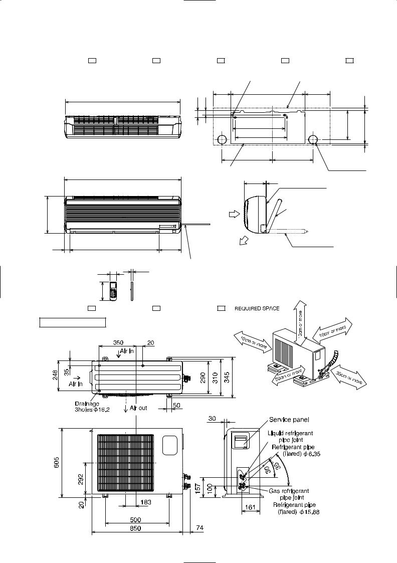
4 
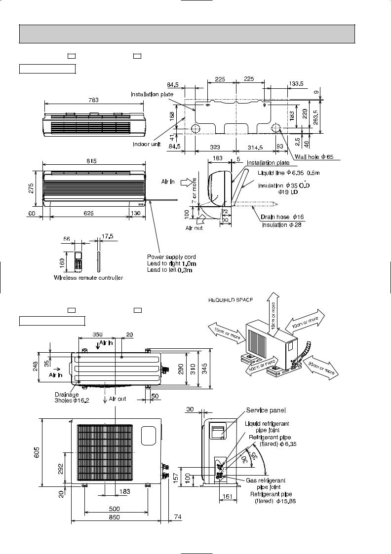
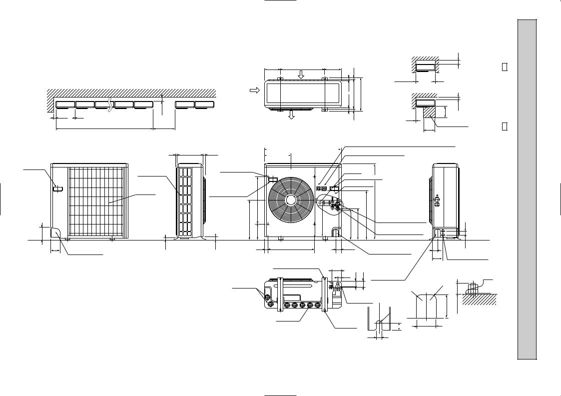
 OUTLINES AND DIMENSIONS
Unit: mm
MSH-07NV - E1 MSH-09NV - E1 MSH-07NV - E2 MSH-09NV - E2
INDOOR UNIT
MUH-07NV - E1 MUH-09NV - E1 MUH-07NV - E2 MUH-09NV - E2
OUTDOOR UNIT
11
Unit: mm
MSH-12NV - E1 MSH-12NV - E2
INDOOR UNIT


 9.52
9.52 


MUH-12NV - E1 MUH-12NV - E2 OUTDOOR UNIT
|
|
|
|
|
|
|
|
|
|
sides |
|
|
|
|
|
|
|
or |
right/left |
|
only |
||
|
|
|
|
front |
|
top |
has |
. |
|||
|
|
|
|
|
unobstructed |
||||||
|
|
|
vacant, |
||||||||
If |
the |
|
|
the |
|
|
|
|
|||
|
|
|
|
|
|
|
|
||||
|
|
|
|
|
|
|
|
|
|
|
|
are |
|
|
10cm |
|
|
|
|
|
|||
to |
be |
|
|
|
|
|
|||||
|
|
|
|
|
|
|
|||||
|
|
|
|
|
|
|
|
|
|
||
If the right/left sides or back side is vacant,the front has only to be 50cm unobstructed.
12
|
|
|
|
|
|
|
Unit: mm |
|
MSH-18NV - E1 MSH-24NV - E1 MSH-18NV - E2 MSH-24NV - E2 |
MSH-18NV - E3 |
|
|
INDOOR UNIT |
4holes 11 20 |
Indoor unit |
|
|
||
995
1015 |
320
50 |
775 |
190 |
|
150 |
648 |
217 |
|
60 |
40 |
|
|
20 |
|
450 |
|
254 |
297 |
|
|
|
|
|
|
450 |
|
|
|
|
438 |
|
352 |
3 |
|
|
|
||
|
Installation plate |
|
Wall hole [75 |
|
|
|
|
|
|
|
190 |
5 |
Installation plate |
|
|
|
|
|
|
|
|
|
Liquid line [8-0.5m |
|
|
|
|
Gas line [12-0.43m |
|
|
Air in |
|
{Insulation [50 O.D |
|
|
|
|
[28 I.D |
|
Air out |
Drain hose [16 |
Insulation [28 |
|
17.5 |
Power supply cord |
|
56 |
Lead to right 2m |
||
|
|||
|
|
Lead to left 1m |
160 |
MUH-18NV - E1 MUH-18NV - E2 MUH-18NV - E3
OUTDOOR UNIT
|
|
|
|
|
|
|
|
|
|
sides |
|
|
|
|
|
|
|
or |
right/left |
|
only |
||
|
|
|
|
front |
|
top |
has |
. |
|||
|
|
|
|
|
unobstructed |
||||||
|
|
|
vacant, |
||||||||
If |
the |
|
|
the |
|
|
|
|
|||
|
|
|
|
|
|
|
|
||||
|
|
|
|
|
|
|
|
|
|
|
|
are |
|
|
10cm |
|
|
|
|
|
|||
to |
be |
|
|
|
|
|
|||||
|
|
|
|
|
|
|
|||||
|
|
|
|
|
|
|
|
|
|
||
If the right/left sides or back side is vacant,the front has only to be 50cm unobstructed.
13
14
Outdoor Unit-Necessary surrounding clearance
(Concentrated installation) The upper side must be open.
100 |
200 |
10 |
For 10 units or less |
1000 |
Air intake
185 |
185 |
(7-9/32) 500(19-11/16) |
(7-9/32) |
Air intake
Air outlet
17 |
|
39.5 27.5 330(13) |
362(14-1/4) |
15 |
|
Outdoor Unit-Necessary surrounding clearance
|
|
200 |
|
Note:Allow adequate |
|
10 |
10 |
upper clearance |
|
Front opening |
|
500 |
150 |
10 |
|
Service space |
|
500 |
|
E2 -24NV-MUH E1 -24NV-MUH
|
|
870(34-1/4) |
Terminal block for indoor and outdoor unit connection |
7 295(11-5/8) 24(1) |
|
|
|
|
|
Terminal block for power line |
|
302 |
|
Handle |
|
Outlet guide |
|
|
|
|
|
|
|
|
|
|
for moving |
|
|
|
Ground |
|
|
|
|
|
|||
|
installation hole |
|
|
|
|
|
|
|
||||
|
Side air intake |
|
|
terminal |
|
|
|
|
|
|||
|
|
|
|
|
|
|
|
|
||||
|
|
|
|
Handle for moving |
|
|
|
|
||||
|
|
|
|
|
|
|
|
|
||||
|
Rear fresh |
|
|
|
Service panel |
|
|
|
|
|||
|
|
|
|
|
|
|
|
|
|
|
|
|
138 |
air intake |
441 |
524179 |
403 |
337 |
352 |
553 |
7/16)-850(33 |
|
|
|
45 |
|
|
Handle for moving |
|
|
|
|
|
|
|
|
|
|
|
|
|
|
|
|
|
|
Refrigerant-pipe flared |
|
|
|
|
|
|
|
|
|
|
|
|
connection [15.88 5/8F |
|
|
||
|
|
|
|
|
|
|
|
Refrigerant-pipe flared |
|
|
|
|
|
|
|
|
|
|
|
|
connection [9.52 3/8F |
|
|
|
|
95 |
23 |
33 |
40 |
524 |
60 |
|
Knock out hole |
|
|
60 |
53 |
|
|
Rear piping hole |
|
|
|
|
|
|
for front piping |
|
|
120 |
Knock out holes for |
|
|
|
|
|
|
|
|
(refrigerant,drainage |
|
power line 2-[27 |
||
|
|
|
|
2-12 23 Oval holes |
|
|
|
and wiring) |
|
|
|
|
|
|
|
|
104 |
|
|
|
|
|
|
|
|
|
|
|
|
(standard bolt M10) |
|
|
Knock out hole |
|
|
|
|
|
|
|
|
|
33 |
42 |
45 |
|
|
|
|
||
|
|
|
|
|
for right piping |
|
|
|
|
|||
|
|
|
|
|
|
|
|
|
|
|
|
|
|
|
Drain hole |
|
|
|
|
(refrigerant,drainage |
|
R20 |
|
||
|
|
|
|
|
|
and wiring) |
R20 |
|
|
|||
|
|
|
|
|
|
|
|
|
|
|||
|
|
|
|
|
|
|
|
|
|
|
||
|
|
|
|
|
Bottom |
|
|
|
|
|||
|
|
|
|
|
|
|
|
80 |
max.25 |
|||
|
|
|
|
|
piping hole |
|
|
|||||
|
|
|
|
|
|
|
|
|
||||
|
|
|
|
Drain hole |
2-U-shaped |
R6 |
|
|
|
Standard bolt length |
||
|
|
|
|
|
|
|
|
|||||
|
|
|
|
notched |
|
|
|
65 |
|
|||
|
|
|
|
|
|
|
|
|
|
|||
|
|
|
|
|
holes |
|
|
17 |
|
|
|
|
|
|
|
|
|
|
|
|
|
|
|
||
|
|
|
|
|
|
|
|
12 |
Front right piping holes- |
|||
|
|
|
|
|
|
|
|
detail figures |
|
|||
|
|
|
|
|
|
|
|
|
|
|||
(inch) mm : Unit
5 |
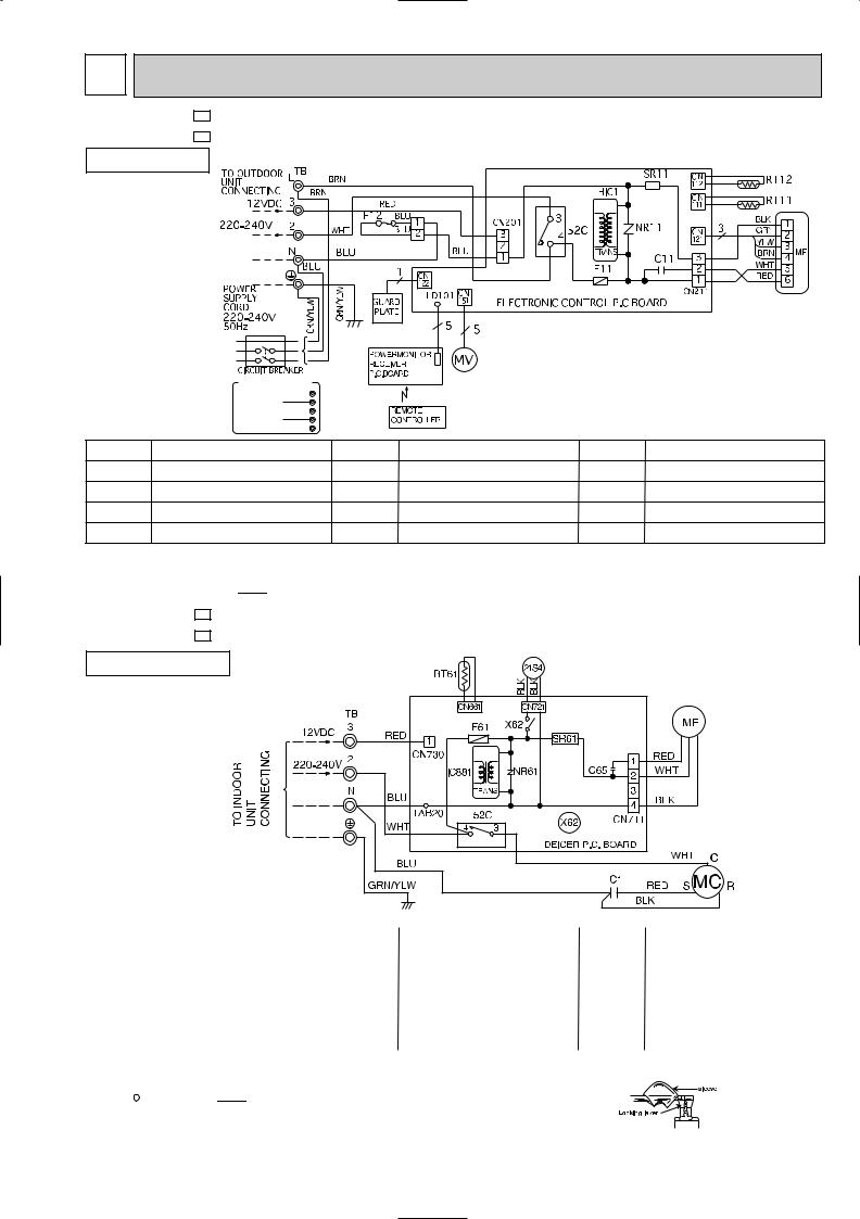
WIRING DIAGRAM |
|
|
|
|||
MSH-07NV - E1 |
MODELS WIRING DIAGRAM |
|
|
||||
MSH-09NV - E1 |
|
|
|
|
|
|
|
INDOOR UNIT |
|
|
|
|
|
|
|
|
|
|
|
|
|
|
|
|
|
|
|
|
|
|
|
|
|
|
|
|
|
|
|
|
|
~ |
|
|
|
|
|
|
|
|
|
|
|
||
|
|
|
|
|
|
|
|
|
|
|
|
|
|
|
|
|
~/N |
|
|
|
|
|
|
|
|
FOR MULTI SYSTEM |
|
|
|
|
|
|
|
|
L |
|
|
|
|
|
|
TO OUTDOOR 12VDC 3 |
|
|
|
|
|
|
|
UNIT |
2 |
|
|
|
|
|
|
N |
|
|
|
|
|
|
|
CONNECTING |
|
|
|
|
|
|
|
; |
|
|
|
|
|
|
|
|
|
|
|
|
|
SYMBOL |
NAME |
|
SYMBOL |
NAME |
SYMBOL |
NAME |
|
C11 |
INDOOR FAN CAPACITOR |
NR11 |
VARISTOR |
TB |
TERMINAL BLOCK |
||
F12 |
FUSE(93:) |
|
|
RT11 |
ROOM TEMPERATURE THERMISTOR |
MV |
VANE MOTOR |
F11 |
FUSE(3.15A) |
|
|
RT12 |
INDOOR COIL THERMISTOR |
SR11 |
SOLID STATE RELAY |
MF |
INDOOR FAN MOTOR |
|
52C |
CONTACTOR |
|
|
|
NOTE:1. For the outdoor electric wiring refer to the outdoor unit electric wiring diagram for servicing.
2.Use copper conductors only.(For field wiring)
3.Symbols below indicate.
 : Terminal block,
  : Connector
MUH-07NV |
- E1 |
MODELS WIRING DIAGRAM |
MUH-09NV |
- E1 |
|
OUTDOOR UNIT
|
|
|
|
|
|
|
|
|
|
|
|
|
|
|
SYMBOL |
NAME |
SYMBOL |
NAME |
SYMBOL |
NAME |
|
|
|
|
|
|
C1 |
COMPRESSOR CAPACITOR |
MF |
OUTDOOR FAN MOTOR |
X62 |
REVERSING VALVE COIL RELAY |
|
|
|
|
|
|
C65 |
OUTDOOR FAN MOTOR CAPACITOR |
NR61 |
VARISTOR |
21S4 |
REVERSING VALVE COIL |
52C |
CONTACTOR |
RT61 |
DEFROST THERMISTOR |
IC881 |
DC/DC CONVERTER |
F61 |
FUSE(2A) |
SR61 |
SOLID STATE RELAY |
|
|
|
|
|
|
|
|
MC |
COMPRESSOR(INNER THERMOSTAT) |
TB |
TERMINAL BLOCK |
|
|
NOTE:1. Use copper conductors only.(For field wiring)
2.Since the indoor and outdoor unit connecting wires have polarity, connect them according to the numbers.
3.Symbols below indicate.
 : Terminal block,


 : Connector
4.“ ”show the terminals with a lock mechanism, so they cannot be removed when you pull the lead wire.
Be sure to pull the wire by pushing the locking lever(projected part) of the terminal with a finger.
1.Slide the sleeve. 2.Pull the wire while
pushing the locking lever.
15
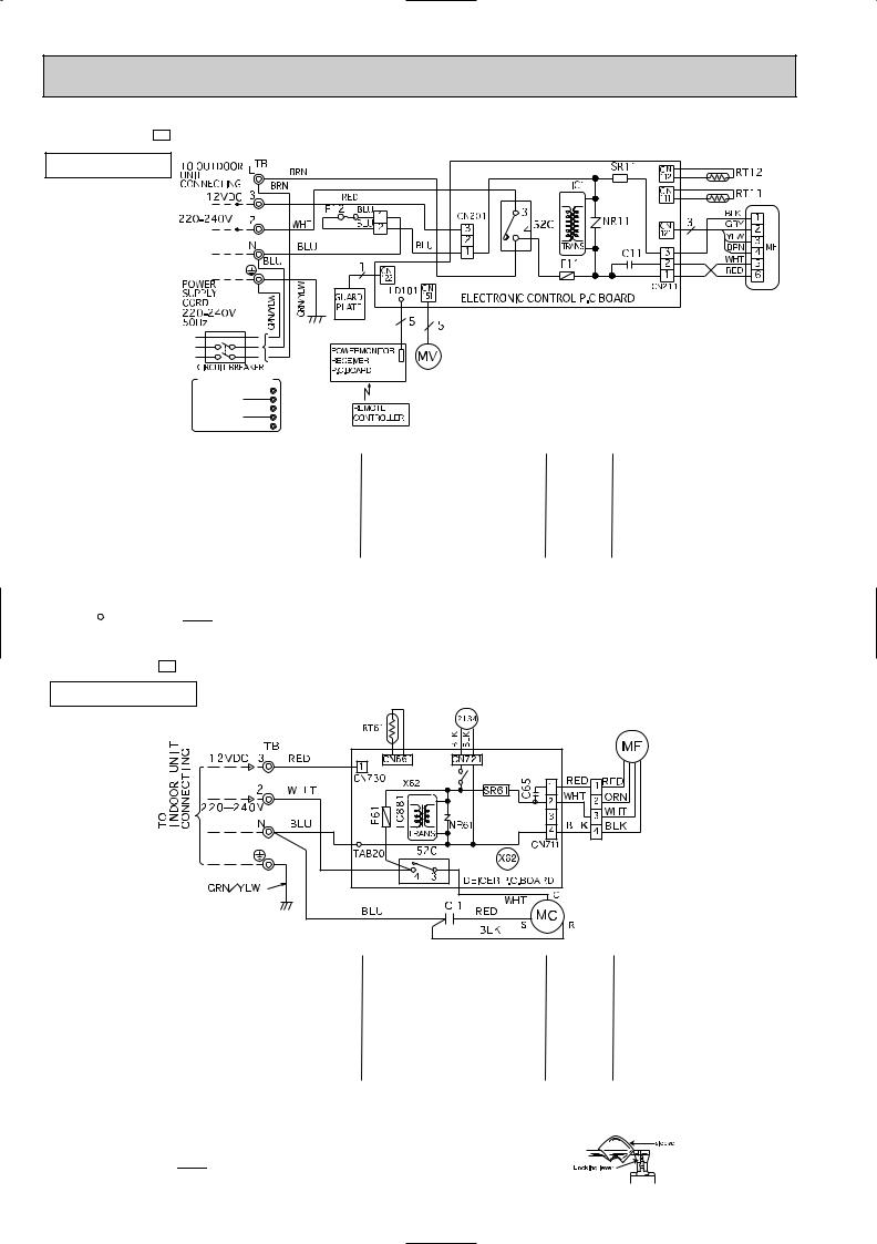
MSH-12NV - E1 MODEL WIRING DIAGRAM
INDOOR UNIT |
|
|
|
|
|
|
|
|
|
|
|
|
|
|
|
|
~ |
|
|
|
|
||
|
|
|
|
|
|
|
|
~/N |
|
|
|
|
FOR MULTI SYSTEM |
|
|
|
|
L |
|
|
TO OUTDOOR 12VDC 3 |
|
|
|
UNIT |
2 |
|
|
N |
|
|
|
CONNECTING |
|
|
|
; |
|
|
|
|
|
|
SYMBOL |
NAME |
SYMBOL |
NAME |
SYMBOL |
NAME |
|
|
|
|
|
|
C11 |
INDOOR FAN CAPACITOR |
NR11 |
VARISTOR |
TB |
TERMINAL BLOCK |
F12 |
FUSE(93:) |
RT11 |
ROOM TEMPERATURE THERMISTOR |
MV |
VANE MOTOR |
F11 |
FUSE(3.15A) |
RT12 |
INDOOR COIL THERMISTOR |
SR11 |
SOLID STATE RELAY |
MF |
INDOOR FAN MOTOR |
52C |
CONTACTOR |
|
|
NOTE:1. For the outdoor electric wiring refer to the outdoor unit electric wiring diagram for servicing.
2.Use copper conductors only.(For field wiring)
3.Symbols below indicate.
 : Terminal block,
  : Connector
MUH-12NV - E1 MODEL WIRING DIAGRAM
OUTDOOR UNIT
|
|
|
|
|
|
|
|
|
|
SYMBOL |
NAME |
SYMBOL |
NAME |
SYMBOL |
NAME |
|
|
|
|
|
|
C1 |
COMPRESSOR CAPACITOR |
MF |
OUTDOOR FAN MOTOR |
X62 |
REVERSING VALVE COIL RELAY |
|
|
|
|
|
|
C65 |
OUTDOOR FAN MOTOR CAPACITOR |
NR61 |
VARISTOR |
21S4 |
REVERSING VALVE COIL |
|
|
|
|
|
|
52C |
CONTACTOR |
RT61 |
DEFROST THERMISTOR |
IC881 |
DC/DC CONVERTER |
|
|
|
|
|
|
F61 |
FUSE(2A) |
SR61 |
SOLID STATE RELAY |
|
|
MC |
COMPRESSOR(INNER THERMOSTAT) |
TB |
TERMINAL BLOCK |
|
|
NOTE:1. Use copper conductors only.(For field wiring)
2.“ ”show the terminals with a lock mechanism, so they cannot be removed when you pull the lead wire.
Be sure to pull the wire by pushing the locking lever(projected part) of the terminal with a finger.
3.Symbols below indicate.
 : Terminal block,
  : Connector
1.Slide the sleeve. 2.Pull the wire while
pushing the locking lever.
16
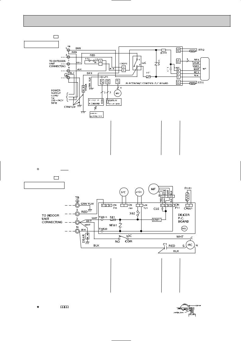
MSH-18NV - E1
INDOOR UNIT
MODEL WIRING DIAGRAM
|
|
|
|
|
|
|
|
|
|
|
|
SYMBOL |
NAME |
SYMBOL |
NAME |
SYMBOL |
NAME |
|
|
|
|
|
|
C11 |
INDOOR FAN CAPACITOR |
NR11 |
VARISTOR |
TB |
TERMINAL BLOCK |
|
|
|
|
|
|
F12 |
FUSE(93:) |
RT11 |
ROOM TEMPERATURE THERMISTOR |
DSAR |
SURGE ABSORBER |
F11 |
FUSE(3.15A) |
RT12 |
INDOOR COIL THERMISTOR |
HIC1 |
DC/DC CONVERTER |
MF |
INDOOR FAN MOTOR |
IC141 |
HYBRID IC |
|
|
MV |
VANE MOTOR |
52C |
CONTACTOR |
|
|
NOTE:1. For the outdoor electric wiring refer to the outdoor unit electric wiring diagram for servicing.
2.Use copper conductors only.(For field wiring)
3.Symbols below indicate.
 : Terminal block,
  : Connector
MUH-18NV - E1 MODEL WIRING DIAGRAM
OUTDOOR UNIT
|
|
|
|
|
SYMBOL |
NAME |
SYMBOL |
NAME |
SYMBOL |
NAME |
|
|
|
|
|
|
C1 |
COMPRESSOR CAPACITOR |
MF |
OUTDOOR FAN MOTOR |
X62 |
REVERSING VALVE COIL RELAY |
C65 |
OUTDOOR FAN MOTOR CAPACITOR |
NR61 |
VARISTOR |
21S4 |
REVERSING VALVE COIL |
DSAR |
SURGE ABSORBER |
RT61 |
DEFROST THERMISTOR |
52C |
CONTACTOR |
F61 |
FUSE(2A) |
SR61 |
SOLID STATE RELAY |
|
|
|
|
|
|
|
|
MC |
COMPRESSOR<INNER THERMOSTAT> |
TB |
TERMINAL BLOCK |
|
|
NOTE:1. Use copper conductors only.(For field wiring)
2.Since the indoor and outdoor unit connecting wires have polarity, connect them according to the numbers.
3.Symbols below indicate.
: Terminal block, |
: Connector |
4.“ ”show the terminals with a lock mechanism, so they cannot be removed when you pull the lead wire.
Be sure to pull the wire by pushing the locking lever(projected part) of the terminal with a finger.
1.Slide the sleeve. 2.Pull the wire while
pushing the locking lever.
17
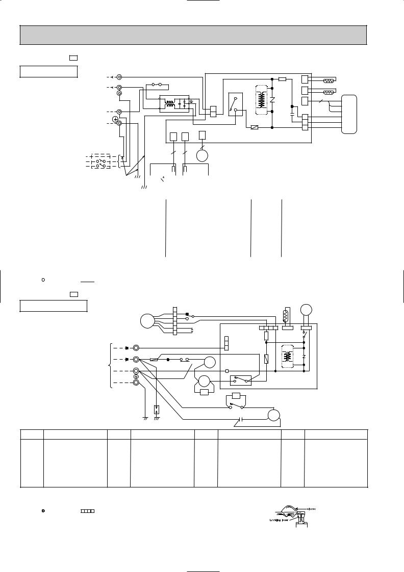
MSH-24NV - E1 MODEL WIRING DIAGRAM
INDOOR UNIT |
220-240V~ 3 TB |
RED |
F12 |
|
|
|
|
|
|
CN |
|
RT12 |
|||
|
220-240V~ 2 |
|
|
|
|
|
|
|
HIC1 |
|
|
||||
|
WHT |
|
|
|
|
|
IC141 |
112 |
|
||||||
|
|
|
|
|
|
|
|
|
|||||||
|
|
|
|
|
|
|
CN |
|
RT11 |
||||||
TO OUTDOORL |
|
|
|
NF |
|
|
|
|
|
NR11 |
|
||||
BRN |
BLU2 |
|
3 BLU |
|
|
111 |
3 |
||||||||
|
|
4 |
CN |
BRN |
|
||||||||||
UNIT |
|
|
1 |
|
|
4 |
|
CN201 |
3 52C |
121 |
|
YLW |
|
||
CONNECTING N |
|
BLU |
|
|
|
CN211 |
|
|
|||||||
|
|
|
|
|
|
|
3 |
TRANS |
C11 |
|
GRY |
|
|||
|
|
BLU |
|
|
|
|
|
|
1 |
|
4 |
|
WHT |
MF |
|
|
|
|
|
|
|
|
|
|
WHT |
F11 |
|
2 |
|
RED |
|
|
|
|
|
|
|
|
|
|
|
|
BLK |
|
|||
|
POWER |
|
|
|
|
|
|
|
|
|
|
1 |
|
|
|
|
|
|
|
|
|
|
|
|
|
|
|
|
|
||
|
SUPPLY |
|
|
|
CN |
CN |
|
CN |
ELECTRONIC CONTROL P.C BOARD |
|
|
|
|||
|
CORD |
|
|
|
101 |
102 |
|
151 |
|
|
|
||||
|
|
|
|
|
|
|
|
|
|||||||
|
~/N 220-240V |
|
|
|
|
|
|
|
5 |
|
|
|
|
|
|
|
50Hz |
|
|
|
3 |
|
3 |
|
|
|
|
|
|
|
|
|
|
|
|
|
|
|
|
|
|
|
|
|
|||
|
|
|
|
|
|
MV |
|
|
|
|
|
|
|||
|
|
|
|
RECEIVER |
|
DISPLAY |
|
|
|
|
|
|
|
||
|
CIRCUIT BREAKER |
|
|
|
|
|
P.C.BOARD |
|
|
|
|
|
P.C.BOARD |
|
|
|||||
|
|
|
|
|
|
|
|
|
||||||||||||
|
GRN/YLW |
|
|
|
|
|
|
|
|
|
|
|
|
|
|
|
|
|
|
|
|
|
|
|
|
|
|
|
|
|
|
|
|
|
|
|
|
|
|
|
|
|
|
|
|
|
|
|
|
|
|
|
|
|
|
|
|
|
|
|
|
|
|
|
|
|
|
|
|
|
|
|
|
|
|
|
|
|
|
|
|
|
|
|
|
|
|
|
|
|
|
REMOTE |
|
|
|
|
|
|
|
|||||
|
|
|
|
|
|
|
|
CONTROLLER |
|
|
|
|
|
|
|
|||||
|
|
|
|
|
|
|
|
|
|
|
|
|
|
|||||||
SYMBOL |
NAME |
|
SYMBOL |
|
|
|
|
|
|
|
NAME |
SYMBOL |
NAME |
|||||||
|
|
|
|
|
|
|
|
|
||||||||||||
C11 |
INDOOR FAN MOTOR CAPACITOR |
|
|
|
NR11 |
VARISTOR |
TB |
TERMINAL BLOCK |
||||||||||||
|
|
|
|
|
|
|
|
|
||||||||||||
F12 |
FUSE(93:) |
|
|
|
RT11 |
ROOM TEMPERATURE THERMISTOR |
HIC1 |
DC/DC CONVERTER |
||||||||||||
F11 |
FUSE(3.15A) |
|
|
|
RT12 |
INDOOR COIL THERMISTOR |
NF |
NOISE FILTER |
||||||||||||
|
|
|
|
|
|
|
|
|||||||||||||
MF |
INDOOR FAN MOTOR |
|
|
IC141 |
HYBRID IC |
|
|
|||||||||||||
MV |
VANE MOTOR |
|
|
|
52C |
CONTACTOR |
|
|
||||||||||||
NOTE:1. For the outdoor electric wiring refer to the outdoor unit electric wiring diagram for servicing.
2.Use copper conductors only.(For field wiring)
3.Symbols below indicate.
 : Terminal block,
  : Connector
MUH-24NV - E1 MODEL WIRING DIAGRAM
OUTDOOR UNIT |
|
|
|
|
|
6 |
|
X1 |
|
|
|
|
RT61 |
21S4 |
|
||
|
|
|
|
|
|
|
1 5 |
|
|
BRN |
|
|
|
||||
|
|
|
|
|
|
YLW |
5 YLW |
|
|
|
|
|
|
||||
|
|
|
|
|
|
BLK |
4 BLK |
|
|
|
|
|
|
|
|
BLK BLK |
|
|
|
|
|
MF |
WHT |
3WHT 3 |
|
|
|
|
|
|
|
||||
|
|
|
|
|
|
ORNRED |
2 ORNRED |
|
C2 |
|
|
CN711 1 2 3 4 |
CN661 |
CN721 |
|
||
|
|
|
TB |
|
|
|
1 |
|
|
|
|
CN730 |
SR61 |
X62 |
|
||
|
|
|
|
|
|
|
|
|
|
|
3 |
|
|
|
|
||
|
|
|
|
|
|
|
|
|
|
|
|
|
|
|
|
||
|
INDOORTO |
UNIT CONNECTING |
12VDC 3 |
|
|
RED |
|
VLT |
|
|
2 |
|
F61 |
P.C. BOARD |
|
||
|
|
|
|
|
|
|
|
3 4 |
|
||||||||
|
|
|
|
|
|
TB2 |
|
BLU 8 |
X1 |
1 |
|
|
IC881 |
NR61 |
|
||
|
|
|
|
|
|
|
|
|
|
|
|||||||
|
|
|
|
|
|
WHT |
|
|
|
|
|
|
|
|
|||
|
|
|
220-240V~2 WHT F |
ORN RED |
|
RED7 |
|
|
|
|
|
|
|
||||
|
|
|
N |
|
BLU 26F1 |
|
|
|
TAB20 |
|
TRANS |
|
|
||||
|
|
|
|
|
|
|
|
|
|
52C1 |
YLW |
52C |
|
DEICER |
|
||
|
|
|
|
GRN/YLW |
DSAR |
|
|
|
|
|
|
|
|
||||
|
|
|
|
|
BLU |
|
|
|
C1 RED S MC R |
|
|
||||||
|
|
|
|
|
WHT |
|
|
VLT CR YLW |
CZ |
|
|
|
|
||||
|
|
|
|
|
|
|
WHT |
|
|
|
WHT C |
|
|
||||
|
|
|
|
|
|
|
|
|
|
|
|
1 |
2 |
|
|
|
|
|
|
|
|
|
|
|
|
|
|
|
|
|
BLK |
|
|
|
|
SYMBOL |
NAME |
|
SYMBOL |
|
|
NAME |
|
|
SYMBOL |
|
NAME |
|
SYMBOL |
NAME |
|||
C1 |
COMPRESSOR CAPACITOR |
MF |
OUTDOOR FAN MOTOR |
X62 |
REVERSING VALVE COIL RELAY |
F |
FUSE(2A) |
|
|
|
<INNER THERMOSTAT> |
|
|
|
|
C2 |
OUTDOOR FAN MOTOR CAPACITOR |
NR61 |
VARISTOR |
21S4 |
REVERSING VALVE COIL |
26F1 |
THERMOSTAT (AIR FLOW CONTROL) |
|
|
|
|
|
|
|
|
DSAR |
SURGE ABSORBER 1 |
RT61 |
DEFROST THERMISTOR |
52C |
CONTACTOR |
IC881 |
DC/DC CONVERTER |
|
|
|
|
|
|
|
|
F61 |
FUSE(2A) |
SR61 |
SOLID STATE RELAY |
52C1 |
COMPRESSOR CONTACTOR |
CR |
SURGE ABSORBER 2 |
|
|
|
|
|
|
|
|
MC |
COMPRESSOR<INNER THERMOSTAT> |
TB. TB2 |
TERMINAL BLOCK |
X1 |
FAN MOTOR RELAY |
CZ |
SURGE ABSORBER 3 |
NOTE:1. Use copper conductors only.(For field wiring)
2.Since the indoor and outdoor unit connecting wires have polarity, connect them according to the numbers.
3.Symbols below indicate.
: Terminal block, |
: Connector |
4.“ ”show the terminals with a lock mechanism, so they cannot be removed when you pull the lead wire.
Be sure to pull the wire by pushing the locking lever(projected part) of the terminal with a finger.
1.Slide the sleeve. 2.Pull the wire while
pushing the locking lever.
18
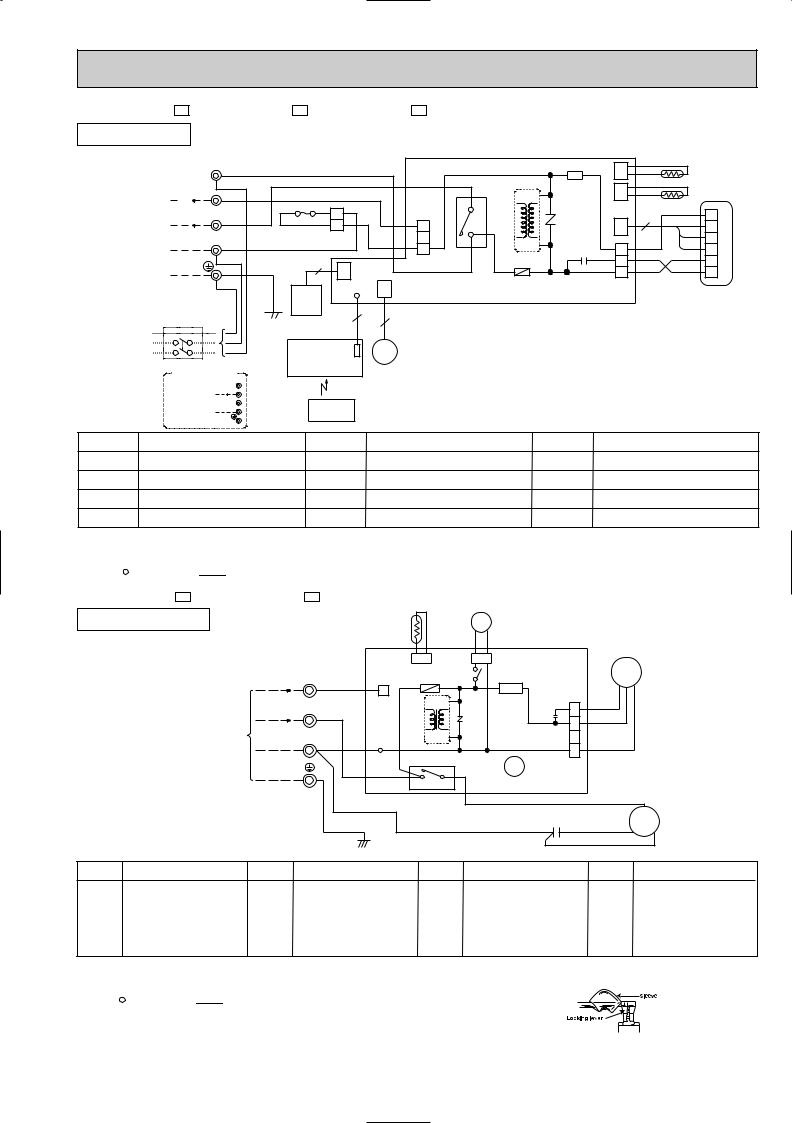
MSH-07NV - E2 MSH-09NV - E2 MSH-12NV - E2 MODELS WIRING DIAGRAM
INDOOR UNIT
|
TO OUTDOOR |
LTB |
BRN |
|
|
|
|
|
|
|
|
SR11 |
CN |
|
RT12 |
|||
|
UNIT |
|
|
|
|
|
|
|
|
|
|
|
112 |
|
||||
|
CONNECTING |
3 |
BRN |
|
|
|
|
|
|
|
HIC1 |
|
CN |
|
RT11 |
|
||
|
12VDC |
RED |
|
|
|
|
|
|
|
|
||||||||
|
|
|
|
|
|
|
|
|
|
111 |
|
|
||||||
|
|
|
|
|
F12 |
BLUBLU 1 |
|
CN201 |
|
|
|
|
|
GRYBLK |
|
|
||
|
220-240V~ |
2 |
|
WHT |
|
3 |
52C |
|
NR11 |
CN |
3 |
1 |
|
|||||
|
|
|
|
|
|
|
2 |
|
3 |
4 |
|
|
|
121 |
|
BRNYLW |
2 |
|
|
|
N |
BLU |
|
|
|
BLU |
2 |
|
|
TRANS |
C11 |
3 |
|
3 |
MF |
||
|
|
|
BLU |
|
|
|
|
|
1 |
|
|
F11 |
|
REDWHT |
4 |
|
||
|
|
|
|
|
1 |
CN |
|
|
|
|
|
2 |
|
5 |
|
|||
|
POWER |
|
|
GRN/YLW |
|
|
122 |
|
|
|
|
|
|
1 |
|
|
6 |
|
|
|
|
|
|
LD101 CN |
|
|
|
|
|
CN211 |
|
|
|
|
|||
|
SUPPLY |
|
GRN/YLW |
GUARD |
|
151 |
ELECTRONIC CONTROL P.C BOARD |
|
|
|
|
|||||||
|
CORD |
|
PLATE |
|
|
|
|
|
|
|
|
|
|
|
|
|||
|
~/N 220-240V |
|
|
|
5 |
5 |
|
|
|
|
|
|
|
|
|
|||
|
50Hz |
|
|
|
|
|
|
|
|
|
|
|
|
|
||||
|
|
|
|
|
POWER MONITOR, |
MV |
|
|
|
|
|
|
|
|
|
|
||
|
|
|
|
|
RECEIVER |
|
|
|
|
|
|
|
|
|
|
|
||
|
CIRCUIT BREAKER |
|
|
|
|
|
|
|
|
|
|
|
|
|
|
|||
|
|
|
P.C.BOARD |
|
|
|
|
|
|
|
|
|
|
|
|
|||
|
FOR MULTI SYSTEM |
|
|
|
|
|
|
|
|
|
|
|
|
|
||||
|
|
|
|
|
|
|
|
|
|
|
|
|
|
|
|
|||
|
|
|
L |
|
|
|
|
|
|
|
|
|
|
|
|
|
|
|
|
TO OUTDOOR 12VDC 3 |
|
|
|
|
|
|
|
|
|
|
|
|
|
|
|
||
|
UNIT |
|
2 |
|
|
|
|
|
|
|
|
|
|
|
|
|
|
|
|
|
N |
|
|
REMOTE |
|
|
|
|
|
|
|
|
|
|
|
||
|
CONNECTING |
|
|
|
|
|
|
|
|
|
|
|
|
|
||||
|
|
|
|
|
|
|
|
|
|
|
|
|
|
|
|
|||
|
|
|
|
CONTROLLER |
|
|
|
|
|
|
|
|
|
|
|
|||
|
|
|
|
|
|
|
|
|
|
|
|
|
|
|
|
|
||
SYMBOL |
NAME |
|
|
SYMBOL |
|
NAME |
|
SYMBOL |
|
|
NAME |
|
|
|||||
C11 INDOOR FAN MOTOR CAPACITOR |
NR11 |
VARISTOR |
|
|
|
TB |
TERMINAL BLOCK |
|
|
|||||||||
F12 |
FUSE(93:) |
|
|
|
RT11 |
ROOM TEMPERATURE THERMISTOR |
HIC1 |
DC/DC CONVERTER |
|
|||||||||
F11 |
FUSE(3.15A) |
RT12 |
INDOOR COIL THERMISTOR |
SR11 |
SOLID STATE RELAY |
MF |
INDOOR FAN MOTOR |
52C |
CONTACTOR |
MV |
VANE MOTOR |
NOTE:1. For the outdoor electric wiring refer to the outdoor unit electric wiring diagram for servicing.
2.Use copper conductors only.(For field wiring)
3.Symbols below indicate.
 : Terminal block,
  : Connector
MUH-07NV - E2 MUH-09NV - E2 |
MODELS WIRING DIAGRAM |
OUTDOOR UNIT |
|
|
|
|
|
RT61 |
|
21S4 |
|
|
|
|
||
|
|
|
|
|
|
|
|
BLK BLK |
|
|
|
|
||
|
|
|
|
|
|
|
|
|
|
|
|
|
|
|
|
|
|
|
TB |
|
|
CN661 |
|
CN721 |
|
|
|
|
|
|
|
|
|
|
|
|
X62 |
|
|
MF |
|
|||
|
|
|
12VDC |
3 |
RED |
|
F61 |
|
|
|
||||
|
|
UNIT CONNECTING |
1 |
|
SR61 |
|
|
|
|
|||||
|
INDOORTO |
|
|
|
|
|
|
CN711 |
|
|||||
|
|
|
|
|
CN730 |
|
|
X62 |
|
|||||
|
|
|
220-240V~ |
2 |
|
|
|
IC881 |
|
NR61 |
C65 |
1 |
WHT |
|
|
|
|
|
N |
BLU |
|
|
|
|
|
2 |
BLK |
|
|
|
|
|
|
|
TRANS |
|
|
|
3 |
|
||||
|
|
|
|
|
|
|
|
|
|
|
|
|
|
|
|
|
|
|
|
|
|
TAB20 |
52C |
|
|
|
4 |
|
|
|
|
|
|
|
|
WHT |
|
|
|
|
|
|
||
|
|
|
|
|
|
|
|
|
|
|
|
|
|
|
|
|
|
|
|
|
|
|
4 3 |
DEICER P.C. BOARD |
WHT |
|
|||
|
|
|
|
|
|
|
BLU |
|
|
|
|
|
C |
|
|
|
|
|
|
|
|
|
|
|
|
|
|
|
|
|
|
|
|
|
GRN/YLW |
|
|
|
C1 |
RED S MC R |
||||
|
|
|
|
|
|
|
|
|
|
|
|
BLK |
|
|
SYMBOL |
NAME |
|
SYMBOL |
|
|
NAME |
SYMBOL |
NAME |
|
SYMBOL |
NAME |
|||
C1 |
COMPRESSOR CAPACITOR |
MF |
OUTDOOR FAN MOTOR |
X62 |
REVERSING VALVE COIL RELAY |
C65 |
FAN MOTOR CAPACITOR |
|
|
|
<INNER THERMOSTAT> |
|
|
|
|
F61 |
FUSE(2A) |
NR61 |
VARISTOR |
21S4 |
REVERSING VALVE COIL |
IC881 |
DC/DC CONVERTER |
MC |
COMPRESSOR<INNER THERMOSTAT> |
RT61 |
DEFROST THERMISTOR |
52C |
CONTACTOR |
TB |
TERMINAL BLOCK |
|
|
|
|
|
|
|
|
SR61 |
SOLID STATE RELAY |
|
|
|
|
|
|
NOTE:1. Use copper conductors only.(For field wiring)
2.Since the indoor and outdoor unit connecting wires have polarity, connect them according to the numbers.
3.Symbols below indicate.
 : Terminal block,
  : Connector
4.“ ”show the terminals with a lock mechanism, so they cannot be removed when you pull the lead wire.
Be sure to pull the wire by pushing the locking lever(projected part) of the terminal with a finger.
1.Slide the sleeve. 2.Pull the wire while
pushing the locking lever.
19
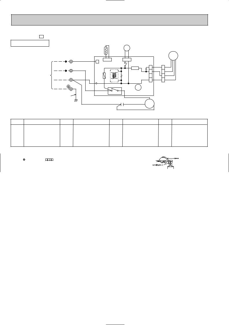
MUH-12NV - E2 |
|
MODEL WIRING DIAGRAM |
|
|
|
|
|
|
|
|
|
|||||||
OUTDOOR UNIT |
|
|
|
|
|
|
|
|
|
|
|
|
|
|
|
|
||
|
|
|
|
|
|
|
|
RT61 |
|
|
21S4 |
|
|
|
|
|
||
|
|
|
|
|
|
|
|
|
|
BLK |
BLK |
|
|
|
|
|
||
|
|
|
|
TB |
|
|
|
|
|
|
|
|
|
|
MF |
|
||
|
|
|
|
|
|
|
|
|
|
|
|
|
|
|
|
|
||
|
|
|
12VDC |
3 |
|
RED |
1 |
CN661 |
|
CN721 |
|
|
|
|
|
|||
|
|
|
|
|
|
|
|
|
|
X62 |
|
|
|
|
|
|
||
|
TO INDOORUNIT |
CONNECTING |
|
|
|
|
|
CN730 |
|
|
|
C65 |
1 |
RED 1 RED |
|
|||
|
220-240V~ 2 |
WHT |
|
|
|
|
SR61 |
|
||||||||||
|
|
|
|
|
|
|
|
|||||||||||
|
|
|
|
|
|
|
2 |
WHT 2 ORN |
|
|||||||||
|
|
|
|
|
|
|
IC881 |
|
|
NR61 |
|
|
|
|||||
|
|
N |
BLU |
|
|
|
|
|
|
3 |
3 WHT |
|
||||||
|
|
|
|
TRANS |
|
|
4 |
BLK 4 BLK |
|
|||||||||
|
|
|
|
|
|
|
|
|
|
|||||||||
|
|
|
|
|
|
F61 |
52C |
|
|
|
|
|
||||||
|
|
|
|
|
|
|
|
TAB20 |
|
|
|
X62 |
CN711 |
|
|
|||
|
|
|
|
|
|
|
|
|
|
|
|
|
|
|
|
|
|
|
|
|
|
GRN/YLW |
|
|
|
|
4 |
3 |
|
DEICER P.C.BOARD |
|
|
|||||
|
|
|
|
|
|
|
|
|
|
|
|
|
|
C |
|
|
||
|
|
|
|
|
|
|
|
|
|
|
C1 |
|
WHT |
|
|
|||
|
|
|
|
|
|
|
|
BLU |
|
|
RED |
MC |
|
|
||||
|
|
|
|
|
|
|
|
|
|
|
|
|
|
|||||
|
|
|
|
|
|
|
|
|
|
|
|
|
|
|
|
|||
|
|
|
|
|
|
|
|
|
|
|
|
|
BLK |
|
S |
R |
|
|
|
|
|
|
|
|
|
|
|
|
|
|
|
|
|
|
|
|
|
SYMBOL |
NAME |
|
SYMBOL |
|
|
NAME |
|
SYMBOL |
|
|
NAME |
|
SYMBOL |
NAME |
||||
C1 |
COMPRESSOR CAPACITOR |
MF |
OUTDOOR FAN MOTOR |
X62 |
REVERSING VALVE COIL RELAY |
C65 |
FAN MOTOR CAPACITOR |
|
|
|
<INNER THERMOSTAT> |
|
|
|
|
F61 |
FUSE(2A) |
NR61 |
VARISTOR |
21S4 |
REVERSING VALVE COIL |
IC881 |
DC/DC CONVERTER |
MC |
COMPRESSOR<INNER THERMOSTAT> |
RT61 |
DEFROST THERMISTOR |
52C |
CONTACTOR |
TB |
TERMINAL BLOCK |
|
|
|
|
|
|
|
|
SR61 |
SOLID STATE RELAY |
|
|
|
|
|
|
NOTE:1. Use copper conductors only.(For field wiring)
2.Since the indoor and outdoor unit connecting wires have polarity, connect them according to the numbers.
3.Symbols below indicate.
: Terminal block, |
: Connector |
4.“ ”show the terminals with a lock mechanism, so they cannot be removed when you pull the lead wire.
Be sure to pull the wire by pushing the locking lever(projected part) of the terminal with a finger.
1.Slide the sleeve. 2.Pull the wire while
pushing the locking lever.
20
MSH-18NV - E2 MODEL WIRING DIAGRAM
INDOOR UNIT |
|
|
|
|
|
|
|
|
|
|
|
|
|
|
|
|
|
|
|
|
~/N |
|
|
FOR MULTI SYSTEM |
|
|
|
L |
|
TO OUTDOOR 12VDC 3 |
|
|
UNIT |
2 |
|
N |
|
|
CONNECTING |
|
|
; |
|
|
|
|
|
SYMBOL |
NAME |
SYMBOL |
NAME |
SYMBOL |
NAME |
|
|
|
|
|
|
C11 |
INDOOR FAN CAPACITOR |
NR11 |
VARISTOR |
TB |
TERMINAL BLOCK |
|
|
|
|
|
|
F12 |
FUSE(93:) |
RT11 |
ROOM TEMPERATURE THERMISTOR |
DSAR |
SURGE ABSORBER |
F11 |
FUSE(3.15A) |
RT12 |
INDOOR COIL THERMISTOR |
HIC1 |
DC/DC CONVERTER |
|
|
|
|
|
|
MF |
INDOOR FAN MOTOR |
IC141 |
HYBRID IC |
|
|
MV |
VANE MOTOR |
52C |
CONTACTOR |
|
|
NOTE:1. For the outdoor electric wiring refer to the outdoor unit electric wiring diagram for servicing.
2.Use copper conductors only.(For field wiring)
3.Symbols below indicate.
 : Terminal block,
  : Connector
MUH-18NV - E2 MODEL WIRING DIAGRAM
OUTDOOR UNIT
|
|
|
|
|
|
|
|
|
SYMBOL |
NAME |
SYMBOL |
NAME |
SYMBOL |
NAME |
|
|
|
|
|
|
C1 |
COMPRESSOR CAPACITOR |
MF |
OUTDOOR FAN MOTOR |
X62 |
REVERSING VALVE COIL RELAY |
|
|
|
|
|
|
C65 |
OUTDOOR FAN MOTOR CAPACITOR |
NR61 |
VARISTOR |
21S4 |
REVERSING VALVE COIL |
|
|
|
|
|
|
DSAR |
SURGE ABSORBER |
RT61 |
DEFROST THERMISTOR |
52C |
CONTACTOR |
|
|
|
|
|
|
F61 |
FUSE(2A) |
SR61 |
SOLID STATE RELAY |
IC881 |
DC/DC CONVERTER |
MC |
COMPRESSOR<INNER THERMOSTAT> |
TB |
TERMINAL BLOCK |
|
|
NOTE:1. Use copper conductors only.(For field wiring)
2.Since the indoor and outdoor unit connecting wires have polarity, connect them according to the numbers.
3.Symbols below indicate.
 : Terminal block,


 : Connector
4.“ ”show the terminals with a lock mechanism, so they cannot be removed when you pull the lead wire.
Be sure to pull the wire by pushing the locking lever(projected part) of the terminal with a finger.
1.Slide the sleeve. 2.Pull the wire while
pushing the locking lever.
21
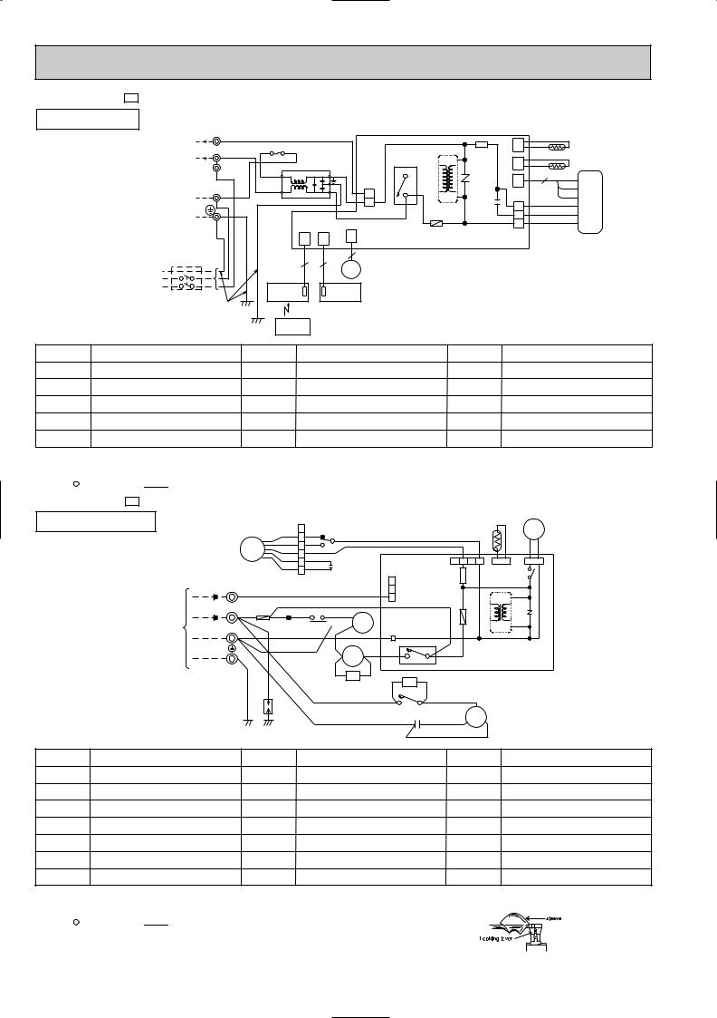
MSH-24NV - E2 MODEL WIRING DIAGRAM
INDOOR UNIT |
TB |
|
|
|
|
|
|
|
|
|
|
|
|
|
220-240V~ 3 |
RED |
|
|
|
|
|
|
|
|
|
||
|
|
|
|
|
|
|
|
CN |
|
RT12 |
|||
|
220-240V~ 2 |
|
|
F12 |
|
|
|
|
|
|
|||
|
WHT |
|
|
|
HIC1 |
IC141 |
112 |
|
|
||||
|
|
|
|
|
|
CN |
|
RT11 |
|||||
|
L |
|
|
|
NF |
|
|
|
|
NR11 |
|
||
|
|
|
BLU 2 |
3BLU |
|
|
111 |
|
|||||
|
TO OUTDOOR |
BRN |
|
4 |
|
CN |
3 |
BRN |
|||||
|
UNIT |
|
|
1 |
|
|
CN201 |
52C |
121 |
|
YLW |
||
|
CONNECTING N |
BLU |
|
|
4 |
3 |
3 |
TRANS |
C11 |
CN211 |
|
GRY |
|
|
|
BLU |
|
|
|
|
1 |
|
F11 |
4 |
|
WHT MF |
|
|
|
|
|
|
|
|
WHT |
|
|
2 |
|
RED |
|
|
POWER |
|
|
|
|
|
|
|
|
BLK |
|||
|
|
|
|
|
|
|
|
|
|
1 |
|
||
|
SUPPLY |
|
|
|
CN |
CN |
CN |
|
|
|
|
|
|
|
CORD |
|
|
|
151 ELECTRONIC CONTROL P.C BOARD |
|
|
||||||
|
|
|
|
101 |
102 |
|
|
||||||
|
~/N 220-240V |
|
|
|
|
5 |
|
|
|
|
|
|
|
|
50Hz |
|
|
|
3 |
3 |
|
|
|
|
|
|
|
|
|
|
|
|
MV |
|
|
|
|
|
|
||
|
|
|
|
|
|
|
|
|
|
|
|
|
|
|
|
|
|
RECEIVER |
DISPLAY |
|
|
|
|
|
|
||
|
CIRCUIT BREAKER |
|
P.C.BOARD |
P.C.BOARD |
|
|
|
|
|
|
|||
|
GRN/YLW |
|
|
|
|
|
|
|
|
|
|
||
|
|
|
|
REMOTE |
|
|
|
|
|
|
|
|
|
|
|
|
|
CONTROLLER |
|
|
|
|
|
|
|
|
|
SYMBOL |
NAME |
|
SYMBOL |
|
|
NAME |
|
SYMBOL |
|
|
NAME |
||
C11 |
INDOOR FAN CAPACITOR |
|
NR11 |
VARISTOR |
|
|
TB |
TERMINAL BLOCK |
|||||
F12 |
FUSE(93:) |
|
|
RT11 |
ROOM TEMPERATURE THERMISTOR |
NF |
NOISE FILTER |
||||||
F11 |
FUSE(3.15A) |
|
|
RT12 |
INDOOR COIL THERMISTOR |
HIC1 |
DC/DC CONVERTER |
||||||
MF |
INDOOR FAN MOTOR |
IC141 |
HYBRID IC |
MV |
VANE MOTOR |
52C |
CONTACTOR |
NOTE:1. For the outdoor electric wiring refer to the outdoor unit electric wiring diagram for servicing.
2.Use copper conductors only.(For field wiring)
3.Symbols below indicate.
 : Terminal block,
  : Connector
MUH-24NV - E2 |
MODEL WIRING DIAGRAM |
|
|
|
|
|
|
|
|
|
|
||||||||
OUTDOOR UNIT |
|
|
|
|
|
|
6 |
X1 |
|
|
|
|
|
|
|
|
RT61 |
21S4 |
|
|
|
|
|
|
|
|
|
|
|
|
BRN |
|
|
|
|
||||
|
|
|
|
|
|
|
YLW |
5 YLW 1 |
5 |
|
|
|
|
|
|
|
|
||
|
|
|
|
|
|
|
BLK |
4 BLK |
|
|
|
|
|
|
|
|
|
|
BLK BLK |
|
|
|
|
|
MF |
WHT |
3 WHT 3 |
|
|
|
|
|
|
|
|
|
|||
|
|
|
|
|
|
|
ORN |
2 ORN |
C2 |
|
|
|
|
CN711 1 2 3 4 |
CN661 |
CN721 |
|||
|
|
|
|
TB |
|
|
RED |
1 RED |
|
|
CN730 |
|
|
SR61 |
|
X62 |
|||
|
|
|
|
|
|
|
|
|
|
|
3 |
|
|
|
|
|
|
||
|
|
TO INDOOR UNIT CONNECTING |
12VDC |
3 |
|
|
RED |
|
|
|
|
2 |
|
|
|
|
|
|
|
|
|
|
|
|
WHT |
|
|
1 |
|
|
|
|
|
IC881 |
NR61 |
||||
|
|
|
|
|
|
|
|
|
|
|
|
|
|
||||||
|
|
|
|
|
|
|
|
|
|
|
|
|
|
|
|
||||
|
|
220-240V~ 2 WHT F ORN RED |
RED 8 |
|
|
|
|
|
|
|
|
|
|||||||
|
|
|
N |
|
|
TB2 26F1 |
BLU 7 X1 |
|
|
|
|
|
|
TRANS |
|||||
|
|
|
|
|
|
|
|
TAB20 |
|
|
|
|
|
||||||
|
|
|
|
|
BLU |
VLT |
|
|
|
|
|
|
|
|
|
||||
|
|
|
|
|
|
|
|
A2 YLW |
|
52C |
|
|
|
||||||
|
|
|
|
|
|
|
|
|
|
|
|
F61 |
|
|
|
||||
|
|
|
|
|
|
|
|
A1 52C1 |
|
|
3 4 |
|
|
|
DEICER |
||||
|
|
|
|
|
|
|
|
|
|
|
|
|
|
|
P.C. BOARD |
||||
|
|
|
|
|
|
WHT |
|
|
|
|
|
|
|
|
|
|
|
||
|
|
|
|
|
RN/YLWG |
|
VLT CR YLW |
|
CZ |
|
|
|
|
|
|
||||
|
|
|
|
|
|
WHT |
|
WHT |
52C1 WHT |
|
|
|
|
||||||
|
|
|
|
|
DSAR |
|
|
|
|
|
|
WHT |
C |
|
|
||||
|
|
|
|
|
|
|
|
|
|
1 |
2 |
|
|
|
|
||||
|
|
|
|
|
|
BLU |
|
|
|
S MC R |
|
||||||||
|
|
|
|
|
|
|
|
|
C1 |
|
RED |
|
|||||||
|
|
|
|
|
|
|
|
|
|
|
|
|
|
|
BLK |
|
|
|
|
SYMBOL |
|
NAME |
|
|
SYMBOL |
|
|
NAME |
|
|
SYMBOL |
NAME |
|||||||
C1 |
COMPRESSOR CAPACITOR |
MF |
OUTDOOR FAN MOTOR |
|
X62 |
REVERSING VALVE COIL RELAY |
|||||||||||||
C2 |
FAN MOTOR CAPACITOR |
|
NR61 |
VARISTOR |
|
|
|
|
|
|
21S4 |
REVERSING VALVE COIL |
|||||||
DSAR |
SURGE ABSORBER 1 |
|
|
RT61 |
DEFROST THERMISTOR |
|
52C |
CONTACTOR |
|||||||||||
CR |
SURGE ABSORBER 2 |
|
|
SR61 |
SOLID STATE RELAY |
|
|
52C1 |
COMPRESSOR CONTACTOR |
||||||||||
CZ |
SURGE ABSORBER 3 |
|
|
TB,TB2 |
TERMINAL BLOCK |
|
|
|
IC881 |
DC/DC CONVERTER |
|||||||||
F61 |
FUSE(2A) |
|
|
|
|
|
F |
FUSE(2A) |
|
|
|
|
|
|
|
X1 |
FAN MOTOR RELAY |
||
MC |
COMPRESSOR<INNER THERMOSTAT> |
|
26F1 |
THERMOSTAT (AIR FLOW CONTROL) |
|
|
|
|
|||||||||||
NOTE:1. Use copper conductors only.(For field wiring)
2.Since the indoor and outdoor unit connecting wires have polarity, connect them according to the numbers.
3.Symbols below indicate.
 : Terminal block,


 : Connector
4.“ ”show the terminals with a lock mechanism, so they cannot be removed when you pull the lead wire.
Be sure to pull the wire by pushing the locking lever(projected part) of the terminal with a finger.
1.Slide the sleeve. 2.Pull the wire while
pushing the locking lever.
22
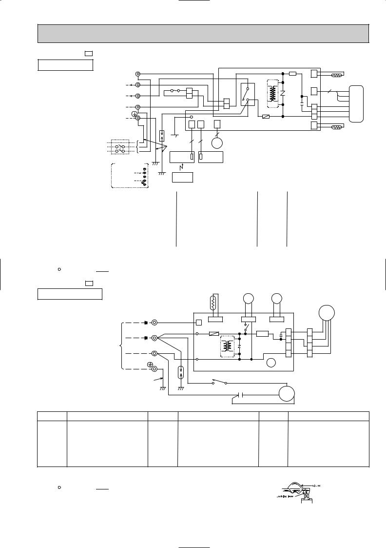
MSH-18NV - E3 MODEL WIRING DIAGRAM
INDOOR UNIT TO OUTDOOR |
LTB BRN |
|
|
|
|
|
|
|
|
|
|
|
|
UNIT |
|
|
|
|
|
|
|
|
CN |
|
RT12 |
||
CONNECTING |
BRN |
|
|
|
|
|
|
HIC1 |
IC141 |
112 |
|
||
12VDC |
|
|
|
|
|
|
|
|
|
||||
3 |
|
RED |
|
|
|
|
|
|
|
|
|
||
F12 |
|
|
|
|
|
|
|
|
3 |
|
|||
|
|
BLU |
|
|
|
|
|
NR11 C11 |
CN |
BRN |
|||
220-240V~2 |
2 |
|
|
|
4 |
52C |
|||||||
WHT |
BLU |
|
|
CN201 |
121 |
|
YLW |
||||||
|
|
|
1 |
|
|
3 |
|
|
|||||
|
N |
|
|
|
|
|
3 |
|
|
CN211 |
|
GRY |
|
|
BLU |
|
|
BLU |
|
TRANS |
|
WHT MF |
|||||
|
|
|
1 |
|
4 |
|
|||||||
|
BLU |
BRN |
|
|
|
|
|
F11 |
|
2 |
|
RED |
|
|
|
|
|
|
|
|
|
BLK |
|||||
POWER |
|
|
RN/YLWG |
LD1 |
|
|
|
|
|
1 |
|
||
|
|
|
|
|
|
|
|
|
|||||
SUPPLY |
|
|
CN |
CN |
|
CN |
|
|
|
CN |
|
RT11 |
|
CORD |
|
DSAR |
101 |
102 |
|
151 ELECTRONIC CONTROL P.C BOARD |
111 |
|
|||||
~/N 220-240V |
|
|
|
5 |
|
|
|
|
|
|
|||
50Hz |
|
|
|
|
|
|
|
|
|
|
|||
|
|
3 |
3 |
|
|
|
|
|
|
|
|||
|
|
|
MV |
|
|
|
|
|
|
||||
|
|
GRN/YLW |
|
|
|
|
|
|
|||||
CIRCUIT BREAKER |
|
RECEIVER |
|
DISPLAY |
|
|
|
|
|
|
|||
|
P.C.BOARD |
|
P.C.BOARD |
|
|
|
|
|
|
||||
|
|
|
|
|
|
|
|
|
|
||||
FOR MULTI SYSTEM
|
L |
|
|
12VDC 3 |
|
||
TO OUTDOOR |
2 |
REMOTE |
|
UNIT |
|||
N |
CONTROLLER |
||
CONNECTING |
|||
|
|
||
SYMBOL |
NAME |
SYMBOL |
NAME |
SYMBOL |
NAME |
|
|
|
|
|
|
C11 |
INDOOR FAN CAPACITOR |
NR11 |
VARISTOR |
TB |
TERMINAL BLOCK |
|
|
|
|
|
|
F12 |
FUSE(93:) |
RT11 |
ROOM TEMPERATURE THERMISTOR |
DSAR |
SURGE ABSORBER |
F11 |
FUSE(3.15A) |
RT12 |
INDOOR COIL THERMISTOR |
HIC1 |
DC/DC CONVERTER |
MF |
INDOOR FAN MOTOR |
IC141 |
HYBRID IC |
|
|
MV |
VANE MOTOR |
52C |
CONTACTOR |
|
|
NOTE:1. For the outdoor electric wiring refer to the outdoor unit electric wiring diagram for servicing.
2.Use copper conductors only.(For field wiring)
3.Symbols below indicate.
 : Terminal block,
  : Connector
MUH-18NV - E3 MODEL WIRING DIAGRAM
OUTDOOR UNIT |
|
|
|
|
|
|
|
|
|
|
21S4 |
|
52C |
|
|
|
|
||
|
|
|
|
|
|
|
RT61 |
|
|
|
|
|
|
|
|||||
|
|
|
|
|
|
|
|
|
BLK |
BLK |
|
VLT |
VLT |
|
|
|
|
||
|
|
|
|
TB |
|
|
|
|
|
|
|
|
|
MF |
|||||
|
|
|
|
|
CN730 CN661 |
|
|
|
|
|
|
|
|
||||||
|
|
|
12VDC |
3 |
|
RED |
CN721 |
|
CN720 |
|
|
|
|
||||||
|
|
|
|
|
|
|
1 |
F61 |
|
X62 |
|
|
|
|
|
|
|
|
|
|
TO UNITINDOOR |
CONNECTING |
220-240V~2 |
|
WHT |
|
|
|
|
|
|
|
RED |
1 |
RED |
||||
|
|
IC881 |
|
NR61 |
|
X62 |
CN711 |
|
|
||||||||||
|
|
|
|
|
|
|
|
|
|
SR61 |
C65 |
1 |
|
|
|||||
|
|
|
|
|
|
WHT |
TAB21 |
|
|
|
|
|
|
2 |
WHT 2 ORN |
||||
|
|
|
|
N |
|
|
|
|
|
|
|
|
|
|
3 |
|
3 WHT |
||
|
|
|
|
BLU |
|
|
|
|
|
|
|
|
|
|
|||||
|
|
|
|
|
|
|
TRANS |
|
|
|
|
4 |
BLK 4 BLK |
||||||
|
|
|
|
|
|
|
|
|
|
|
|
|
|
||||||
|
|
|
|
|
|
|
|
|
|
|
|
|
|
|
|
|
|
|
|
|
|
|
GRN/YLW |
|
DSAR |
TAB20 |
52C |
COM |
|
WHT |
|
|
|
|
|
||||
|
|
|
|
WHT NO |
|
|
|
|
|
|
|||||||||
|
|
|
|
|
|
|
|
|
DEICER P.C.BOARD |
|
|
|
|
|
|
||||
|
|
|
|
|
|
|
|
|
|
|
C1 |
|
|
|
|
C |
|
|
|
|
|
|
|
|
|
|
BLU |
|
|
|
RED |
|
MC |
|
|
|
|||
|
|
|
|
|
|
|
|
|
|
|
|
|
|
|
|||||
|
|
|
|
|
|
|
|
|
|
|
|
|
|
|
R |
|
|
||
|
|
|
|
|
|
|
|
|
|
|
|
BLK |
|
S |
|
|
|
||
|
|
|
|
|
|
|
|
|
|
|
|
|
|
|
|
|
|
||
SYMBOL |
NAME |
|
SYMBOL |
|
NAME |
|
|
SYMBOL |
|
|
|
NAME |
|||||||
C1 |
COMPRESSOR CAPACITOR |
MF |
OUTDOOR FAN MOTOR |
X62 |
REVERSING VALVE COIL RELAY |
C65 |
OUTDOOR FAN MOTOR CAPACITOR |
NR61 |
VARISTOR |
21S4 |
REVERSING VALVE COIL |
DSAR |
SURGE ABSORBER |
RT61 |
DEFROST THERMISTOR |
52C |
CONTACTOR |
|
|
|
|
|
|
F61 |
FUSE(2A) |
SR61 |
SOLID STATE RELAY |
IC881 |
DC/DC CONVERTER |
|
|
|
|
|
|
MC |
COMPRESSOR<INNER THERMOSTAT> |
TB |
TERMINAL BLOCK |
|
|
NOTE:1. Use copper conductors only.(For field wiring)
2.Since the indoor and outdoor unit connecting wires have polarity, connect them according to the numbers.
3.Symbols below indicate.
 : Terminal block,


 : Connector
4.“ ”show the terminals with a lock mechanism, so they cannot be removed when you pull the lead wire.
Be sure to pull the wire by pushing the locking lever(projected part) of the terminal with a finger.
1.Slide the sleeve. 2.Pull the wire while
pushing the locking lever.
23
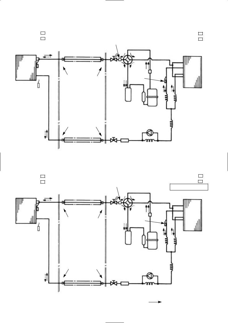
|
6 |
|
|
REFRIGERANT SYSTEM DIAGRAM |
|
||||||
|
|
|
|
|
|
|
|
|
|
|
|
|
MSH-07NV - E1 |
|
|
|
Unit:mm |
||||||
|
|
|
|
MUH-07NV - E1 |
|||||||
|
MSH-07NV - E2 |
Refrigerant pipe [ 9.52 |
Muffler |
Reversing valve |
MUH-07NV - E2 |
||||||
|
INDOOR UNIT |
|
OUTDOOR UNIT |
||||||||
|
|
(Option) |
|
(4-way valve) |
|||||||
|
|
|
|
|
|
|
|
(with heat insulator) |
|
|
|
|
|
|
|
|
|
|
|
|
|
|
|
|
|
|
|
Indoor coil |
|
|
|
|
|||
|
|
Indoor |
|
|
|
|
|
||||
|
|
heat |
|
thermistor |
|
Stop valve |
Strainer |
Outdoor |
|||
|
|
exchanger |
RT12 |
|
heat |
||||||
|
|
|
(with service Defrost |
||||||||
|
|
|
exchanger |
||||||||
|
|
|
|
|
|
|
|
Flared connection |
port) |
thermistor |
|
|
|
|
|
|
|
|
|
|
|||
|
|
|
|
|
|
|
|
|
|
RT61 |
|
|
Room temperature |
|
|
|
Capillary tube |
||||||
|
thermistor |
|
|
|
|
|
|||||
|
RT11 |
|
|
|
|
|
|
[1.4x800 (2 pcs) |
|||
|
|
|
|
|
|
|
|
|
Accumulator |
|
|
|
|
|
|
|
|
|
|
Flared connection |
|
Check |
Capillary tube |
|
|
|
|
|
|
|
|
|
[1.6x750 |
||
|
|
|
|
|
|
|
|
|
valve |
||
|
|
|
|
|
|
|
|
|
|
||
|
|
|
|
|
|
|
|
|
Strainer |
Reversing valve coil |
|
|
|
|
|
|
|
|
|
|
|
|
(4-way valve coil) |
|
|
|
|
|
|
|
|
Refrigerant pipe [6.35 |
Stop valve |
Capillary tube |
heating ON |
|
|
|
|
|
|
|
|
cooling OFF |
|||
|
|
|
|
|
|
|
|
(Option) |
|
[1.4x850 |
|
|
|
|
|
|
|
|
|
|
|
||
 Refrigerant flow in cooling
|
|
|
|
(with heat insulator) |
MSH-09NV - E1 |
|
|||
MSH-09NV - E2 |
Refrigerant pipe [9.52 |
|||
INDOOR UNIT |
|
|||
|
(Option) |
|||
|
|
|
|
(with heat insulator) |
|
|
Indoor coil |
|
|
|
Indoor |
|
||
|
heat |
thermistor |
|
|
|
exchanger |
RT12 |
|
|
|
|
|
|
|
Flared connection
Room temperature thermistor
RT11
Flared connection
Refrigerant pipe [6.35 (Option)
(with heat insulator)
 Refrigerant flow in heating
Muffler Reversing valve (4-way valve)
Stop valve |
Strainer |
|
(with service |
Defrost |
|
port) |
thermistor |
|
RT61 |
||
|
Accumulator
|
Check |
|
valve |
Strainer |
|
Stop valve |
Capillary tube |
|
[1.6x1300 |
Unit:mm
MUH-09NV - E1 MSH-09NV - E2
OUTDOOR UNIT
Outdoor heat exchanger
Capillary tube [1.4x800 (2 pcs)
Capillary tube [1.6x400
Reversing valve coil (4-way valve coil) heating ON
cooling OFF
 Refrigerant flow in cooling Refrigerant flow in heating
24
 Loading...