


PLA-A-AA

Air-Conditioners
PLA-A·AA
Deutsch
INSTALLATION MANUAL
For safe and correct use, read this manual and the outdoor unit installation manual thoroughly before installing
the air-conditioner unit.
FOR INSTALLER
Nederlands
Español
Italiano
ППЛУИО¿
Português
Dansk
Svenska
English
MANUAL DE INSTALACIÓN
Para un uso correcto y seguro, lea detalladamente este manual y el manual de instalación de la unidad exterior
antes de instalar la unidad de aire acondicionado.
PARA EL INSTALADOR
Español
Contents
1. Safety precautions ................................................................................... 2
2. Installation location .................................................................................. 3
3. Installing the indoor unit ........................................................................... 3
4. Installing the refrigerant piping ................................................................. 5
5. Drainage piping work ............................................................................... 6
1. Safety precautions
s Before installing the unit, make sure you read all the “Safety precau-
tions”.
s Please report to your supply authority or obtain their consent before
connecting this equipment to the power supply system.
Warning:
Describes precautions that must be observed to prevent danger of injury or
death to the user.
Caution:
Describes precautions that must be observed to prevent damage to the unit.
Warning:
• Ask a dealer or an authorized technician to install the unit.
• For installation work, follow the instructions in the Installation Manual and use
tools and pipe components specifically made for use with refrigerant specified
in the outdoor unit installation manual.
• The unit must be installed according to the instructions in order to minimize
the risk of damage from earthquakes, typhoons, or strong winds. An incorrectly installed unit may fall down and cause damage or injuries.
• The unit must be securely installed on a structure that can sustain its weight.
• If the air conditioner is installed in a small room, measures must be taken to
prevent the refrigerant concentration in the room from exceeding the safety
limit in the event of refrigerant leakage. Should the refrigerant leak and cause
the concentration limit to be exceeded, hazards due to lack of oxygen in the
room may result.
6. Electrical work .......................................................................................... 7
7. Test run .................................................................................................. 12
8. System control ....................................................................................... 15
9. Installing the grille .................................................................................. 15
10. Easy maintenance function .................................................................... 17
After installation work has been completed, explain the “Safety Precautions,” use,
and maintenance of the unit to the customer according to the information in the Operation Manual and perform the test run to ensure normal operation. Both the Installation Manual and Operation Manual must be given to the user for keeping. These
manuals must be passed on to subsequent users.
: Indicates a part which must be grounded.
Warning:
Carefully read the labels affixed to the main unit.
• Ventilate the room if refrigerant leaks during operation. If refrigerant comes
into contact with a flame, poisonous gases will be released.
• All electric work must be performed by a qualified technician according to
local regulations and the instructions given in this manual.
• Use only specified cables for wiring.
• The terminal block cover panel of the unit must be firmly attached.
• Use only accessories authorized by Mitsubishi Electric and ask a dealer or
an authorized technician to install them.
• The user should never attempt to repair the unit or transfer it to another location.
• After installation has been completed, check for refrigerant leaks. If refrigerant leaks into the room and comes into contact with the flame of a heater or
portable cooking range, poisonous gases will be released.
1.1. Before installation (Euvironment)
Caution:
• Do not use the unit in an unusual environment. If the air conditioner is installed in areas exposed to steam, volatile oil (including machine oil), or sulfuric
gas, areas exposed to high salt content such as the seaside, the performance
can be significantly reduced and the internal parts can be damaged.
• Do not install the unit where combustible gases may leak, be produced, flow,
or accumulate. If combustible gas accumulates around the unit, fire or explosion may result.
• Do not keep food, plants, caged pets, artwork, or precision instruments in the
direct airflow of the indoor unit or too close to the unit, as these items can be
damaged by temperature changes or dripping water.
1.2. Before installation or relocation
Caution:
• Be extremely careful when transporting the units. Two or more persons are
needed to handle the unit, as it weighs 20 kg, 44lbs or more. Do not grasp the
packaging bands. Wear protective gloves as you can injure your hands on
the fins or other parts.
• Be sure to safely dispose of the packaging materials. Packaging materials,
such as nails and other metal or wooden parts may cause stabs or other
injuries.
1.3. Before electric work
Caution:
• Be sure to install circuit breakers. If not installed, electric shock may result.
• For the power lines, use standard cables of sufficient capacity. Otherwise, a
short circuit, overheating, or fire may result.
• When installing the power lines, do not apply tension to the cables.
• When the room humidity exceeds 80% or when the drainpipe is clogged, water may drip from the indoor unit. Do not install the indoor unit where such
dripping can cause damage.
• When installing the unit in a hospital or communications office, be prepared
for noise and electronic interference. Inverters, home appliances, high-frequency medical equipment, and radio communications equipment can cause
the air conditioner to malfunction or breakdown. The air conditioner may also
affect medical equipment, disturbing medical care, and communications equipment, harming the screen display quality.
• Thermal insulation of the refrigerant pipe is necessary to prevent condensation. If the refrigerant pipe is not properly insulated, condensation will be formed.
• Place thermal insulation on the pipes to prevent condensation. If the drainpipe is installed incorrectly, water leakage and damage to the ceiling, floor,
furniture, or other possessions may result.
• Do not clean the air conditioner unit with water. Electric shock may result.
• Tighten all flare nuts to specification using a torque wrench. If tightened too
much, the flare nut can break after an extended period.
• Be sure to ground the unit. If the unit is not properly grounded, electric shock
may result.
• Use circuit breakers (ground fault interrupter, isolating switch (+B fuse), and
molded case circuit breaker) with the specified capacity. If the circuit breaker
capacity is larger than the specified capacity, breakdown or fire may result.
1.4. Before starting the test run
Caution:
• Turn on the main power switch more than 12 hours before starting operation.
Starting operation just after turning on the power switch can severely damage the internal parts.
• Before starting operation, check that all panels, guards and other protective
parts are correctly installed. Rotating, hot, or high voltage parts can cause
injuries.
2
• Do not operate the air conditioner without the air filter set in place. If the air
filter is not installed, dust may accumulate and breakdown may result.
• Do not touch any switch with wet hands. Electric shock may result.
• Do not touch the refrigerant pipes with bare hands during operation.
• After stopping operation, be sure to wait at least five minutes before turning off
the main power switch. Otherwise, water leakage or breakdown may result.
2. Installation location
7-9/16
6-1/4
6-1/4
3-27/32
6-1/4
33-27/32 to 35-13/16
25/32 to 1-25/32
25/32 to 1-25/32
25/32 to 1-25/32
31-7/8
37-3/8
33-1/16
7-3/4
23-13/16
33-1/16
37-3/8
33-27/32 to 35-13/16
A
B
C
D
C
B
D
A
6-1/4
25/32 to 1-25/32
5-5/16
F
G
E
11/16
+3/16
0
11/16
+3/16
0
4-1/8
1-3/16
C
D
Min. 40
Min. 20
F
H
E
1-15/16 to 2-3/4
5/8
3-1/2
A
7-9/16
G
A
∗6-11/16
∗5-1/2
∗7-15/32
2-3/8 11-1/4 14-23/32
AFDE
B
C
Refer to the outdoor unit installation manual.
3. Installing the indoor unit
Caution:
Install the indoor unit at least 2.4 m, 8 ft above floor or grade level.
1
3
5
7
2
4
6
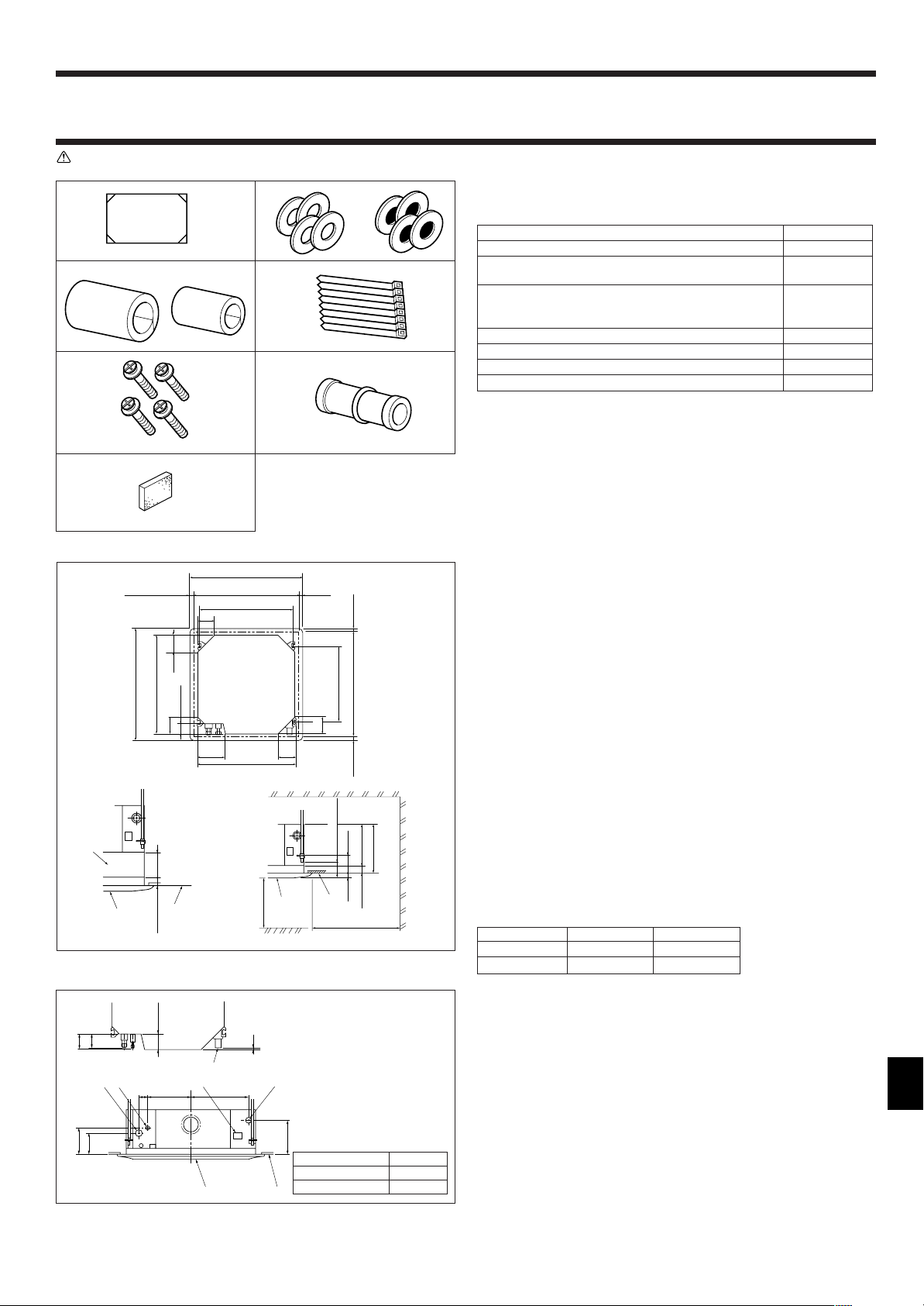
3.1. Check the indoor unit accessories (Fig. 3-1)
The indoor unit should be supplied with the following accessories.
Accessory name Q’ty
1 Installation template 1
2 Washers (with insulation) 4
Washers (without insulation) 4
3 Pipe cover (for refrigerant piping joint)
Small diameter 1
Large diameter 1
4 Band 8
5 Screw with washer (M5 × 25) for mounting grille 4
6 Drain socket 1
7 Insulation 1
Fig. 3-1
Fig. 3-2
(inch)
3.2. Ceiling openings and suspension bolt installation
locations (Fig. 3-2)
• Using the installation template (top of the package) and the gauge (supplied as an
accessory with the grille), make an opening in the ceiling so that the main unit can
be installed as shown in the diagram. (The method for using the template and the
gauge are shown.)
* Before using, check the dimensions of template and gauge, because they
change due to fluctuations of temperature and humidity.
* The dimensions of ceiling opening can be regulated within the range shown in
following diagram; so center the main unit against the opening of ceiling, ensuring that the respective opposite sides on all sides of the clearance between
them becomes identical.
• Use M10 (3/8”) suspension bolts.
* Suspension bolts are to be procured at the field.
• Install securely, ensuring that there is no clearance between the ceiling panel &
grille, and between the main unit & grille.
A Outer side of main unit
B Bolt pitch
C Ceiling opening
D Outer side of Grille
E Grille
F Ceiling
G Multi function casement (option)
H Entire periphery
* Note that the space between ceiling panel of the unit and ceiling slab and etc must be 10 to
15 mm, 25/64-19/32 inch.
Models C D
A12, A18, A24, A30
241, 9-1/2” 258, 10-3/16”
A36, A42 281, 11-1/16” 298, 11-3/4”
(mm, inch)
Fig. 3-3
(mm, inch)
Models A
A12, A18, A24, A30
A36, A42 84, 3-5/16”
(inch)
80, 3-5/32”
3.3. Refrigerant and drainage piping locations of indoor
unit
The figure marked with * in the drawing represent the dimensions of the main unit
excluding those of the optional multi function casement. (Fig. 3-3)
A Drain pipe
B Ceiling
C Grille
D Refrigerant pipe (liquid)
E Refrigerant pipe (gas)
F Water supply inlet
G Main unit
• When the optional multi-functional casement is installed, add 135 mm, 5-5/16 inch
to the dimensions marked on the figure.
3
3. Installing the indoor unit
A
B
C
J
H
I
D
E
F
G
23-13/16
31-57/64
A
D
C
B
A=11/16
+3/16
0
C
D
B
A
11/16
4-1/8(9-29/64)
+3/16
0
A
B
A
C
D
E
F
C
B
G
Min. 1-3/16
D
E
A
C
A
B
3-17/32
3-15/16
5-1/8
13-25/32
70°
G
F
H
I
J
∗6-3/32
∗6-9/16
3-15/16
3-17/32
3-15/16
L
K
M
N
O
∗6-7/32
120°
120°
1
D Ceiling
E Rafter
F Beam
G Roof beam
Fig. 3-4
2
Fig. 3-5
(inch)
A Unit
B Grille
C Pillar
H Use inserts rated at 100-150 kg,
250-350 lbs each (procure locally)
I Suspension bolts M10 (3/8”) (procure
locally)
J Steel reinforcing rod
(inch)
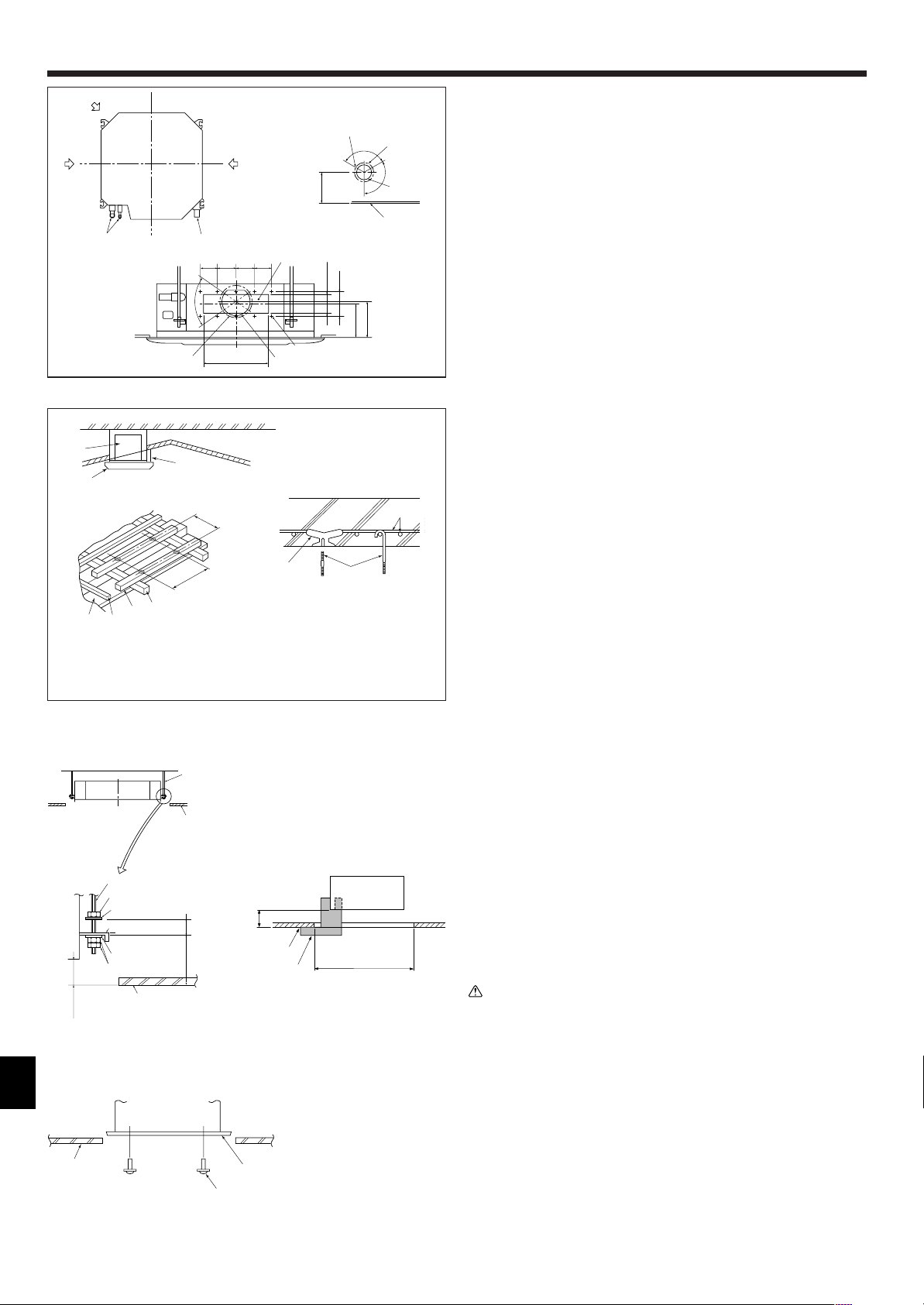
3.4. Branch duct hole and fresh air intake hole (Fig. 3-4)
At the time of installation, use the duct holes (cut out) located at the positions shown
in following diagram, as and when required.
• A fresh air intake hole for the optional multi function casement can also be made.
Note:
The figure marked with * in the drawing represent the dimensions of the main
unit excluding those of the optional multi function casement.
When installing the optional multi function casement, add 135 mm, 5-5/16 inch
to the dimensions marked on the figure.
When installing the branch ducts, be sure to insulate adequately. Otherwise
condensation and dripping may occur.
A Branch duct hole
B Indoor unit
C Fresh air intake hole
D Drain pipe
E Refrigerant pipe
F Branch duct hole diagram (view from
either side)
G Cut out hole
H 14-ø2.8 mm, ø1/8 inch burring hole
I ø150 mm, ø5-29/32 inch cut out hole
J ø175 mm, ø6-7/8 inch burring hole pitch
K Fresh air intake hole diagram
L 3-ø2.8 mm, ø1/8 inch burring hole
M ø125 mm, ø4-29/32 inch burring hole pitch
N ø100 mm, ø3-15/16 inch cut out hole
O Ceiling
3.5. Suspension structure (Give site of suspension
strong structure) (Fig. 3-5)
• The ceiling work differs according to the construction of the building. Building con-
structors and interior decorators should be consulted for details.
(1) Extent of ceiling removal: The ceiling must be kept completely horizontal and the
ceiling foundation (framework: wooden slats and slat holders) must be reinforced
in order to protect the ceiling from vibration.
(2) Cut and remove the ceiling foundation.
(3) Reinforce the ends of the ceiling foundation where it has been cut and add ceiling
foundation for securing the ends of the ceiling board.
(4) When installing the indoor unit on a slanting ceiling, attach a pillar between the
ceiling and the grille and set so that the unit is installed horizontally.
1 Wooden structures
• Use tie beams (single storied houses) or second floor beams (two story houses) as
reinforcing members.
• Wooden beams for suspending air conditioners must be sturdy and their sides
must be at least 6 cm, 2-3/8 inch long if the beams are separated by not more than
90 cm, 35-7/16 inch and their sides must be at least 9 cm, 3-9/16 inch long if the
beams are separated by as much as 180 cm, 70-7/18 inch. The size of the suspension bolts should be ø10 (3/8”). (The bolts do not come with the unit.)
2 Ferro-concrete structures
Secure the suspension bolts using the method shown, or use steel or wooden hangers, etc. to install the suspension bolts.
A Suspension bolt
B Ceiling
C Nut
D Washer (with insulation)
E Mounting plate
F Washer (without insulation)
G Check using the Installation gauge
(inch)
3.6. Unit suspension procedures (Fig. 3-6)
Suspend the main unit as shown in the diagram.
Figures given in parentheses represent the dimensions in case of installing optional
multi function casement.
1. In advance, set the parts onto the suspension bolts in the order of the washers
(with insulation), washers (without insulation) and nuts (double).
• Fit the washer with cushion so that the insulation faces downward.
• In case of using upper washers to suspend the main unit, the lower washers (with
insulation) and nuts (double) are to be set later.
2. Lift the unit to the proper height of the suspension bolts to insert the mounting
plate between washers and then fasten it securely.
3. When the main unit can not be aligned against the mounting hole on the ceiling, it
is adjustable owing to a slot provided on the mounting plate.
• Make sure that step A is performed within 17-22 mm, 11/16-7/8 inch. Damage
could result by failing to adhere to this range. (Fig. 3-7)
Fig. 3-6
A Main unit
B Ceiling
C Gauge
D Ceiling opening dimensions
Fig. 3-7
Caution:
Use the top half of the box as a protective cover to prevent dust or debris from
getting inside the unit prior to installation of the decorative cover or when applying ceiling materials.
3.7. Confirming the position of main unit and tightening the suspension bolts (Fig. 3-8)
A Main unit
4
Fig. 3-8
B Ceiling
C Installation template (top of the
package)
D Screw with washer (Accessory)
• Using the gauge attached to the grille, ensure that the bottom of the main unit is
properly aligned with the opening of the ceiling. Be sure to confirm this, otherwise
condensation may form and drip due to air leakage etc.
• Confirm that the main unit is horizontally levelled, using a level or a vinyl tube filled
with water.
• After checking the position of the main unit, tighten the nuts of the suspension bolts
securely to fasten the main unit.
• The installation template (top of the package) can be used as a protective sheet to
prevent dust from entering the main unit when the grilles are left unattached for a while
or when the ceiling materials are to be lined after installation of the unit is finished.
* As for the details of fitting, refer to the instructions given on the Installation template.
B
90° ±0.5°
øA
R1/64 to R1/32
A
45°±2°
4. Installing the refrigerant piping
C
D
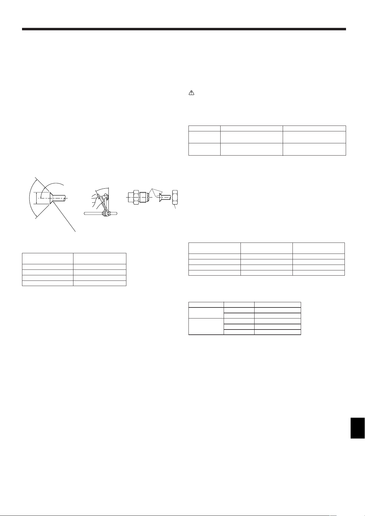
4.1. Precautions
4.1.1. For devices that use R410A refrigerant
• Use ester oil, ether oil, alkylbenzene oil (small amount) as the refrigeration
oil applied to the flared sections.
• Use C1220 copper phosphorus, for copper and copper alloy seamless pipes,
to connect the refrigerant pipes. Use refrigerant pipes with the thicknesses
specified in the table to the below. Make sure the insides of the pipes are
clean and do not contain any harmful contaminants such as sulfuric compounds, oxidants, debris, or dust.
Warning:
When installing or moving the air conditioner, use only the specified refrigerant (R410A) to charge the refrigerant lines. Do not mix it with any other refrigerant and do not allow air to remain in the lines. Air enclosed in the lines can
cause pressure peaks resulting in a rupture and other hazards.
A12, A18 A24, A30, A36, A42
Liquid pipe
Gas pipe
• Do not use pipes thinner than those specified above.
ø6.35 mm, ø1/4 inch ø9.52 mm, ø3/8 inch
thickness 0.8 mm, 1/32 inch thickness 0.8 mm, 1/32 inch
ø12.7 mm, ø1/2 inch ø15.88 mm, ø5/8 inch
thickness 0.8 mm, 1/32 inch thickness 1.0 mm, 3/64 inch
Fig. 4-1
A Flare cutting dimensions
Copper pipe O.D. Flare dimensions
(mm, inch) øA dimensions (mm, inch)
ø6.35, 1/4” 8.7 - 9.1, 11/32 - 23/64
ø9.52, 3/8” 12.8 - 13.2, 1/2 - 33/64
ø12.7, 1/2” 16.2 - 16.6, 41/64 - 21/32
ø15.88, 5/8” 19.3 - 19.7, 49/64 - 25/32
(inch)
4.2. Connecting pipes (Fig. 4-1)
• When commercially available copper pipes are used, wrap liquid and gas pipes
with commercially available insulation materials (heat-resistant to 100 °C, 212 °F or
more, thickness of 12 mm, 1/2 inch or more).
• The indoor parts of the drain pipe should be wrapped with polyethylene foam insu-
lation materials (specific gravity of 0.03, thickness of 9 mm, 23/64 inch or more).
• Apply thin layer of refrigerant oil to pipe and joint seating surface before tightening
flare nut.
• Use two wrenches to tighten piping connections.
• Use refrigerant piping insulation provided to insulate indoor unit connections. Insu-
late carefully.
B Flare nut tightening torque
Copper pipe O.D. Flare nut O.D. Tightening torque
(mm, inch) (mm, inch) (N·m, ft·lbs)
ø6.35, 1/4” 17, 43/64 14 - 18, 10 -13
ø9.52, 3/8” 22
ø12.7, 1/2” 26
ø15.88, 5/8” 29
C Apply refrigerating machine oil over the entire flare seat surface.
D Use correct flare nuts meeting the pipe size of the outdoor unit.
Available pipe size
A12, A18
Liquid side
Gas side –ø15.88
? : Factory flare nut attachment to the heat-exchanger.
ø6.35 –
–ø9.52
ø12.7 –
––
, 7/8
, 1-3/64
, 1-9/64
A24, A30,
A36, A42
34 - 42
49 - 61
68 - 82
, 25 - 30
, 35 - 44
, 49 - 59
5
4. Installing the refrigerant piping
B
D
E
A
C
F
J
H
I
B,C
F
G
Max. 65ft
5 to 7ft
A
B
C
B
M
L
K
D
E
D
H
I
G
D
F
F
F
Max. 6inch
J
F
G
7/16
111
B
A
C
C
F
K
H
DEE
I
J
C
Fig. 4-2
5. Drainage piping work
A Refrigerant pipe and insulating ma-
terial
B Pipe cover (large)
C Pipe cover (small)
D Refrigerant pipe (gas)
E Refrigerant pipe (liquid)
F Band
G Cross-sectional view of connection
H Pipe
I Insulating material
J Squeeze
4.3. Indoor unit (Fig. 4-2)
Heat insulation for refrigerant pipes:
1 Wrap the enclosed large-sized pipe cover around the gas pipe, making sure that
the end of the pipe cover touches the side of the unit.
2 Wrap the enclosed small-sized pipe cover around the liquid pipe, making sure
that the end of the pipe cover touches the side of the unit.
3 Secure both ends of each pipe cover with the enclosed bands. (Attach the bands
20 mm from the ends of the pipe cover.)
• After connecting the refrigerant piping to the indoor unit, be sure to test the pipe
connections for gas leakage with nitrogen gas. (Check that there is no refrigerant
leakage from the refrigerant piping to the indoor unit.)
4.4. For twin/triple combination
Refer to the outdoor unit installation manual.
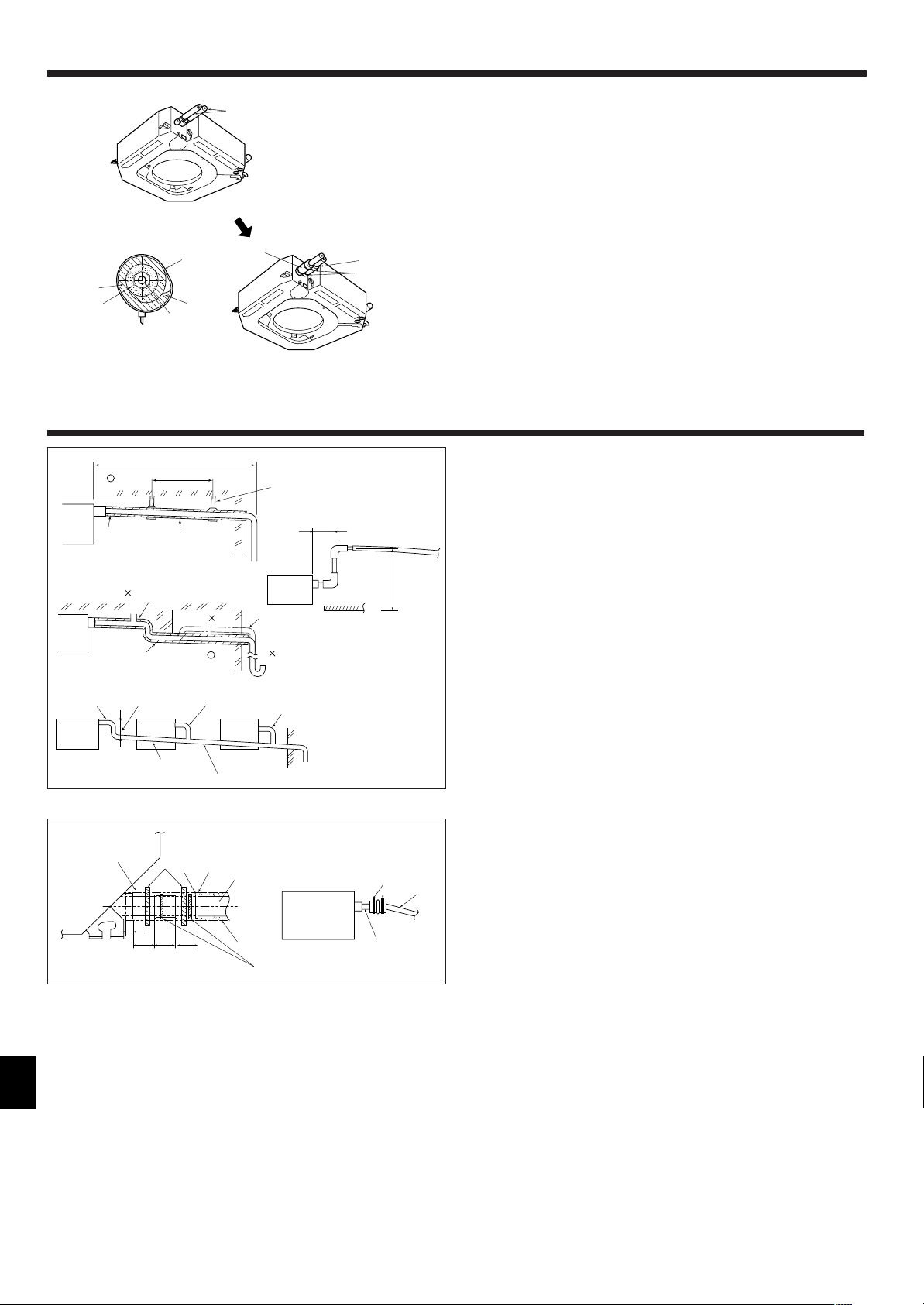
5.1. Drainage piping work (Fig. 5-1)
• Use VP25 (O.D. ø32 mm, 1-1/4 inch PVC TUBE) for drain piping and provide 1/100
or more downward slope.
• Be sure to connect the piping joints using a polyvinyl type adhesive.
• Observe the figure for piping work.
• Use the included drain hose to change the extraction direction.
1 Correct piping
2 Wrong piping
A Insulation (9 mm, 3/8 inch or more)
B Downward slope (1/100 or more)
Grouped piping
D O.D. ø32 mm, 1-1/4 inch PVC TUBE
E Make it as large as possible
F Indoor unit
G Make the piping size large for grouped piping.
H Downward slope (1/100 or more)
C Support metal
K Air bleeder
L Raised
M Odor trap
I O.D. ø38 mm, 1-1/2 inch PVC TUBE for
grouped piping.
(9 mm, 3/8 inch or more insulation)
J Up to 85 cm, 33-7/16 inch
6
Fig. 5-1
(inch)
Fig. 5-2
1. Connect the drain socket (supplied with the unit) to the drain port. (Fig. 5-2)
(Affix the tube using PVC adhesive then secure it with a band.)
2. Install a locally purchased drain pipe (PVC pipe, O.D. ø32 mm, 1-1/4 inch).
(Affix the pipe using PVC adhesive then secure it with a band.)
3. Insulate the tube and pipe. (PVC pipe, O.D. ø32 mm, 1-1/4 inch and socket)
4. Check that drain flows smoothly.
5. Insulate the drain port with insulating material, then secure the material with a
band. (Both insulating material and band are supplied with the unit.)
A Unit
B Insulating material
C Band
D Drain port (transparent)
E Insertion margin
F Matching
G Drain pipe
(O.D. ø32 mm, 1-1/4 inch PVC TUBE)
H Insulating material (purchased locally)
I Transparent PVC pipe
J O.D. ø32 mm, 1-1/4 inch PVC TUBE
(Slope 1/100 or more)
K Drain socket
 Loading...