


Owner’s Guide
LCD Television Models
LT-2240 and LT-3040
visit our website at
www.mitsubishi-tv.com
LT2240_LT3040_OG_v6.ind1 |
|
|
04.1.21, 4:02 PM |
|
|
||
|
|
|
|
CAUTION
RISK OF ELECTRIC SHOCK DO NOT OPEN
CAUTION:
TO REDUCE THE RISK OF ELECTRIC SHOCK, DO NOT REMOVE COVER OR BACK. NO USER SERVICEABLE PARTS INSIDE.
REFER SERVICING TO QUALIFIED SERVICE PERSONNEL.
The lightning flash with arrowhead symbol within an equilateral triangle is intended to alert the user of the presence of uninsulated “dangerous voltage” within the product’s enclosure that may be sufficient magnitude to constitute a risk of electric shock.
The exclamation point within an equilateral triangle is intended to alert the user to the presence of important operating and maintenance (servicing) instructions in the literature accompanying the TV.
Note: This equipment has been tested and found to comply with the limits for a Class B digital device, pursuant to part 15 of the FCC Rules. These limits are designed to provide reasonable protection against harmful interference in a residential installation. This equipment generates, uses and can radiate radio frequency energy and, if not installed and used in accordance with the instructions, may cause harmful interference to radio communications. However, there is no guarantee that interference will not occur in a particular installation. If this equipment does cause harmful interference to radio or television reception, which can be determined by turning the equipment off and on, the user is encouraged to try to correct the interference by one or more of the following measures:
•Reorient or relocate the receiving antenna.
•Increase the separation between the equipment and the receiver.
•Connect the equipment into an outlet on a circuit different from that to which the receiver is connected.
•Consult the dealer or an experienced radio/TV technician for help.
CAUTION: To assure continued FCC compliance, the user must use a shielded video interface cable with bonded ferrite cores at both ends, when using the MonitorLink/DVI input.
Changes or modifications not expressly approved by Mitsubishi could void the user’s authority to operate this equipment.
WARNING:
TO REDUCE THE RISK OF FIRE OR ELECTRIC SHOCK, DO NOT EXPOSE THIS TELEVISION TO RAIN OR MOISTURE.
CAUTION:
TO PREVENT ELECTRIC SHOCK, MATCH WIDE BLADE OF PLUG TO WIDE SLOT, FULLY INSERT.
NOTE TO CATV SYSTEM INSTALLER:
THIS REMINDER IS PROVIDED TO CALL THE CATV SYSTEM INSTALLER’S ATTENTION TO ARTICLE 820-40 OF THE NEC THAT PROVIDES GUIDELINES FOR THE PROPER GROUNDING AND, IN PARTICULAR, SPECIFIES THAT THE CABLE GROUND SHALL BE CONNECTED TO THE GROUNDING SYSTEM OF THE BUILDING, AS CLOSE TO THE POINT OF CABLE ENTRY AS PRACTICAL.
Hg LAMP(S) INSIDE THIS PRODUCT CONTAIN MERCURY AND MUST BE RECYCLED OR DISPOSED OF ACCORDING TO LOCAL, STATE OR FEDERAL LAWS.
LT2240_LT3040_OG_v6.ind2 |
|
|
04.1.21, 4:02 PM |
|
|
||
|
|
|
|

Contents |
|
|
Important Safeguards .................................................................................................................. |
4 |
|
Cleaning Your LCD TV.............................................................................................................. |
6 |
|
Chapter 1 |
Television Overview |
|
Thank You................................................................................................................................... |
8 |
|
Unpacking Your New TV............................................................................................................ |
9 |
|
Special Features ........................................................................................................................... |
9 |
|
Front Control Panel ..................................................................................................................... |
10 |
|
Side Panel Input/Output.............................................................................................................. |
11 |
|
Chapter 2 |
Connections |
|
Connecting an Antenna or Wall Outlet Cable............................................................................. |
14 |
|
Connecting an Antenna to a Cable Box or VCR.......................................................................... |
15 |
|
Connecting an Antenna to a Cable Box and VCR ....................................................................... |
16 |
|
Connecting Audio Components to a Cable Box or VCR ............................................................. |
16 |
|
Connecting an Audio Receiver .................................................................................................... |
17 |
|
Connecting a DVD Player or Other S-Video Device................................................................... |
18 |
|
Connecting a DTV Receiver........................................................................................................ |
19 |
|
Connecting MonitorLink™ or a Computer ................................................................................ |
21 |
|
How Connections Affect the PIP and POP ................................................................................. |
22 |
|
Chapter 3 Remote Control Functions |
|
|
Overview of the TV Layer Buttons.............................................................................................. |
24 |
|
Care and Operation..................................................................................................................... |
25 |
|
Channel Selection........................................................................................................................ |
26 |
|
Sleep Timer ................................................................................................................................. |
26 |
|
Use With Other A/V Products .................................................................................................... |
27 |
|
Special Functions......................................................................................................................... |
29 |
|
Operation of PIP and POP .......................................................................................................... |
29 |
|
Chapter 4 Menu Screen Operations |
|
|
The ViewPoint® Menu System ................................................................................................... |
32 |
|
MAIN Menu ............................................................................................................................. |
33 |
|
SETUP Menu.............................................................................................................................. |
35 |
|
CAPTIONS Menu...................................................................................................................... |
39 |
|
CHANNEL EDIT Menu............................................................................................................ |
41 |
|
V-CHIP LOCK Menu ................................................................................................................ |
43 |
|
ADVANCED FEATURES Menu............................................................................................... |
46 |
|
AUDIO/VIDEO SETTINGS Menu........................................................................................... |
50 |
|
Chapter 5 |
PIP/POP Operations |
|
Available On-Screen Format Sizes......................................................................................................... |
54 |
|
Operation of PIP and POP .......................................................................................................... |
56 |
|
Appendix A: Bypassing the V-Chip Lock.................................................................................... |
57 |
|
Appendix B: HD Input Connection Compatibility ..................................................................... |
58 |
|
Appendix C: Remote Control Programming Codes..................................................................... |
59 |
|
Monitor Tilt/Input Terminal Access/Cable Management............................................................ |
61 |
|
Index |
............................................................................................................................................ |
62 |
Troubleshooting........................................................................................................................... |
64 |
|
Warranty...................................................................................................................................... |
66 |
|
3
LT2240_LT3040_OG_v6.ind3 |
|
|
04.1.21, 4:02 PM |
|
|
||
|
|
|
|
IMPORTANT SAFEGUARDS
Please read the following safeguards for your TV and retain for future reference.
Always follow all warnings and instructions marked on the television.
1.Read, Retain and Follow All Instructions
Read all safety and operating instructions before operating the TV. Retain the safety and operating instructions for future reference. Follow all operating and use instructions.
2.Heed Warnings
Adhere to all warnings on the TV and in the operating instructions.
3.Cleaning
Unplug the TV from the wall outlet before cleaning. Do not use liquid, abrasive, or aerosol cleaners. Cleaners can permanently damage the cabinet and screen. Use a lightly dampened cloth for cleaning.
4.Attachments and Equipment
Never add any attachments and/or equipment without approval of the manufacturer as such additions may result in the risk of fire, electric shock or other personal injury.
5.Water and Moisture
Do not use the TV where contact with or immersion in water is possible. Do not use near bath tubs, wash bowls, kitchen sinks, laundry tubs, swimming pools, etc.
6.Accessories
Do not place the TV on an unstable cart, stand, tripod, or table. The TV may fall, causing serious injury to a child or adult and serious damage to the TV. Use only with a cart, stand, tripod, bracket, or table recommended by the manufacturer, or sold with the TV. Any mounting of the TV should follow the manufacturer’s instructions, and should use UL 1678 listed wall mounting brackets suitable for the weight and mounting surface used.
The TV and cart combination should be moved with care. Quick stops, excessive force, and uneven surfaces may cause the TV and cart combination to overturn.
7.Ventilation
Slots and openings in the cabinet are provided for ventilation and to ensure reliable operation of the TV and to protect it from overheating. Do not block these openings or allow them to be obstructed by placing the TV on a bed, sofa, rug, or other similar surface. Nor should it be placed over a radiator or heat register. If the TV is to be placed in a rack or bookcase, ensure that there is adequate ventilation and that the manufacturer’s instructions have been adhered to.
8.Power Source
This TV should be operated only from the type of power source indicated on the marking label. If you are not sure of the type of power supplied to your home, consult your appliance dealer or local power company. The socketoutlet shall be installed near the equipment and shall be easily accessible.
9.Grounding or Polarization
This TV is equipped with a polarized alternating current line plug having one blade wider than the other. This plug will fit into the power outlet only one way. If you are unable to insert the plug fully into the outlet, try reversing the plug. If the plug should still fail to fit, contact your electrician to replace your obsolete outlet. Do not defeat the safety purpose of the polarized plug.
10.Power-Cord Protection
Power-supply cords should be routed so that they are not likely to be walked on or pinched by items placed upon or against them, paying particular attention to cords at plugs, convenience receptacles, and the point where they exit from the TV.
11.Lightning
For added protection for this TV during a lightning storm, or when it is left unattended and unused for long periods of time, unplug it from the wall outlet and disconnect the antenna or cable system. This will prevent damage to the TV due to lightning and power-line surges.
4
LT2240_LT3040_OG_v6.ind4 |
|
|
04.1.21, 4:02 PM |
|
|
||
|
|
|
|
IMPORTANT SAFEGUARDS, continued
12.Power Lines
An outside antenna system should not be located in the vicinity of overhead power lines or other electric, light or power circuits, or where it can fall into such power lines or circuits. When installing an outside antenna system,
extreme care should be taken to keep from touching such power lines or circuits as contact with them might be fatal.
13.Overloading
Do not overload wall outlets and extension cords as this can result in a risk of fire or electric shock.
14.Object and Liquid Entry
Never push objects of any kind into this TV through openings as they may touch dangerous voltage points or shortout parts that could result in fire or electric shock. Never spill liquid of any kind on or into the TV.
15.Outdoor Antenna Grounding
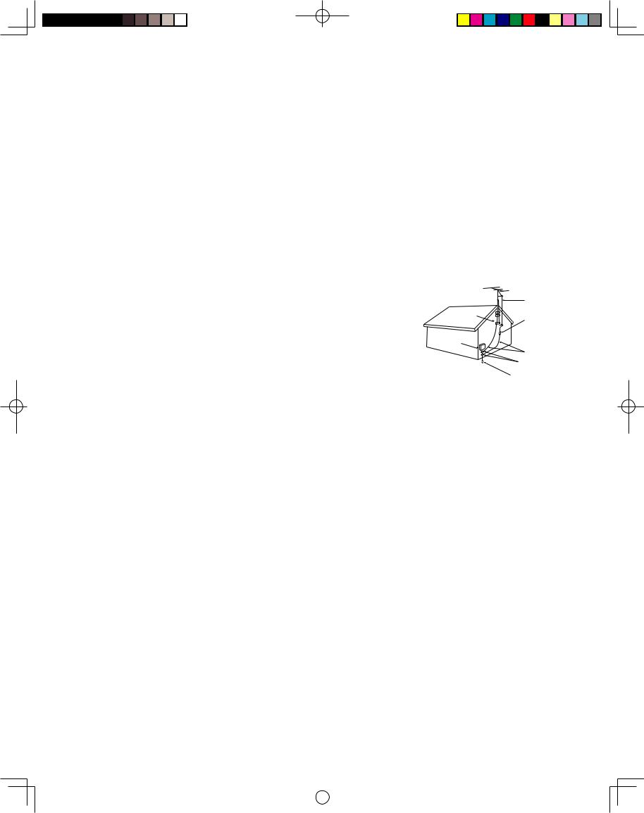
If an outside antenna or cable system is connected to the TV, be sure the antenna or cable system is grounded so as to provide some protection against voltage surges and built-up static charges.
Section 810 of the National Electric Code, ANSI/NFPA No. 70-1984, provides information with respect to proper grounding of the mast and supporting structure, grounding of the lead in wire to an antenna discharge unit, size of grounding conductors, location of antenna discharge unit, connection to grounding electrodes,
EXAMPLE OF ANTENNA GROUNDING
ANTENNA
LEAD IN WIRE
GROUND CLAMP
and requirements for the grounding electrode.
16.Servicing
Do not attempt to service this TV yourself as opening or removing covers may expose you to dangerous voltage or other hazards. Refer all servicing to qualified service personnel.
17.Damage Requiring Service
|
ANTENNA |
|
|
DISCHARGE UNIT |
|
ELECTRIC |
(NEC SECTION 810-20) |
|
|
||
SERVICE |
GROUNDING |
|
EQUIPMENT |
||
CONDUCTORS |
||
|
||
|
(NEC SECTION 810-21) |
|
|
GROUND CLAMPS |
|
|
POWER SERVICE GROUNDING |
|
|
ELECTRODE SYSTEM |
|
NEC — NATIONAL ELECTRICAL CODE |
(NEC ART 250, PART H) |
Unplug the TV from the wall outlet and refer servicing to qualified service personnel under the following conditions:
(a)When the power-supply cord or plug is damaged.
(b)If liquid has been spilled, or objects have fallen into the TV.
(c)If the TV has been exposed to rain or water.
(d)If the TV does not operate normally by following the operating instructions, adjust only those controls that are covered by the operating instructions as an improper adjustment of other controls may result in damage and will often require extensive work by a qualified technician to restore the TV to its normal operation.
(e)If the TV has been dropped or the cabinet has been damaged.
(f)When the TV exhibits a distinct change in performance - this indicates a need for service.
18. Replacement Parts
When replacement parts are required, be sure the service technician has used replacement parts specified by the manufacturer or have the same characteristics as the original part. Unauthorized substitutions may result in fire, electric shock or other hazards.
19. Safety Check
Upon completion of any service or repair to the TV, ask the service technician to perform safety checks to determine that the TV is in safe operating condition.
20.Heat
The product should be situated away from heat sources such as radiators, heat registers, stoves, or other products (including amplifiers) that produce heat. Do not place this product in an enclosed place (bookcase or wall) without proper ventilation. Do not block the vents or openings on this product.
5
LT2240_LT3040_OG_v6.ind5 |
|
|
04.1.21, 4:02 PM |
|
|
||
|
|
|
|
IMPORTANT SAFEGUARDS, continued
21.Transport
(a)Be sure to use another person to lift or carry this display. It is recommended that one hand on each side of the display be used to transport the display.
(b)Use caution when transporting the unit. Be sure that items such as belt buckles, watches, shirt buttons, and zippers do not scratch or rub the screen or cabinet.
22.LCD Monitor
This monitor uses a technology composed of over 2.9 million thin film transistors. It is common to find a few colored (non-active) “dots” on the screen. Do not be alarmed. This is a result of the manufacturing process found in all panels. Your picture performance will not be affected.
CLEANING AND SERVICE
Cleaning
Normally, light dusting with a dry, non-scratching duster will keep your TV clean. If cleaning beyond this is needed, please use the following guidelines:
First, turn off the TV and unplug the power cord from the power outlet.
Top and Sides of the TV:
•Gently wipe down your TV with a soft, nonabrasive cloth such as cotton flannel or a clean cloth diaper, lightly moistened with water. Dry with a second dry, soft, non-abrasive cloth.
General Cleaning Warnings:
•DO NOT allow liquid to enter the TV through the ventilation slots or any crevice.
•DO NOT use any strong or abrasive cleaners as these can scratch the surfaces.
•DO NOT use any commercial cleaners with ammonia, bleach, alcohol, benzine, or thinners as these can dull the surfaces.
•DO NOT spray liquids or cleaners directly on the TV’s surfaces.
•DO NOT scrub or rub the TV harshly. Wipe it gently.
•Excessive moisture or water may damage your TV. Use caution when wiping your TV.
DO NOT use any kind of abrasive or liquid cleaner on the surface of the TV screen.
For further information, please call Consumer Relations at: 800-332-2119
6
LT2240_LT3040_OG_v6.ind6 |
|
|
04.1.21, 4:02 PM |
|
|
||
|
|
|
|
Chapter . . . 1
Television Overview |
|
Thank You.................................................................................................................. |
8 |
Unpacking Your New TV ........................................................................................... |
9 |
Special Features........................................................................................................... |
9 |
Front Control Panel .................................................................................................. |
10 |
Side Panel Input/Output........................................................................................... |
11 |
LT2240_LT3040_OG_v6.ind7 |
|
|
04.1.21, 4:02 PM |
|
|
||
|
|
|
|

Thank You for Your Purchase
Welcome to the wonderful and exciting world of digital television! We are honored that you chose Mitsubishi as your premier home entertainment partner. The development team at Mitsubishi Digital Electronics America (MDEA) understands that our customers demand and expect the very best. MDEA was founded on the
core beliefs and philosophies that drive us to deliver products that implement the latest in advanced television technology.
While some televisions are destined for obsolescence in the near future, MDEA’s televisions are all HDupgradeable. This cornerstone of your home entertainment system will continue to provide unparalleled enjoyment for years to come!
Whether this is your first Mitsubishi consumer electronics product or another addition to your growing
Mitsubishi system, we hope that this television will bring you many hours of enjoyment.
OUR PROMISE
We will engineer and manufacture the upgrades necessary so the HD-upgradeable television you purchased today can be made compatible with near-future advances in digital television and digital interconnectivity. Specifically, we promise that you will be able to have your television upgraded, at a reasonable cost, to include an off-air HDTV tuner, a cable TV tuner (for unscrambled programming), an IEEE 1394 (FireWire®) connection, HAVi system control, and 5C copy protection.
8
LT2240_LT3040_OG_v6.ind8 |
|
|
04.1.21, 4:02 PM |
|
|
||
|
|
|
|
Unpacking Your New TV
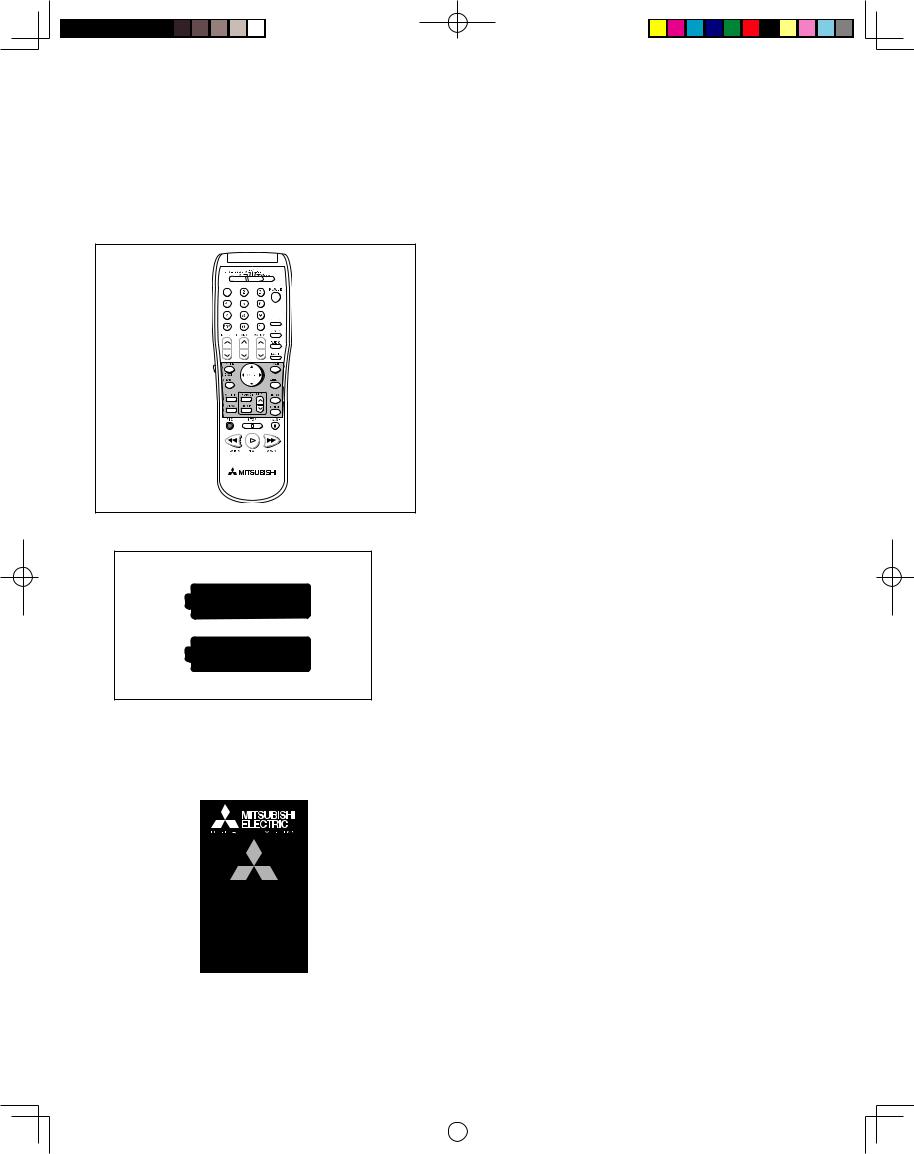
Please take a moment to review the following list of items to ensure that you have received everything including:
Remote Control
(2) AAA Batteries
(1) 75-ohm Coaxial Cable AC Adapter (LT-2240 only)
PRODUCT REGISTRATION
Product Registration Card
Quick Reference Card (not pictured)
Special Features
Your new High Definition (HD) upgradeable LCD television has many special features that make it the perfect addition to your home entertainment system. A few of these special features are:
PIP/POP Viewing Option
Using Picture-in-Picture and Picture-outside- Picture gives you exciting options for viewing favorite programs.
See pages 22, 29 and 56 for more information.
HD Upgradeable
With the use of an optional HDTV receiver
(Mitsubishi HD-5000 or similar model) your Mitsubishi television can display high definition pictures.
See page 21 for connection information.
Multibrand Remote Control
Your Mitsubishi remote control can be programmed to control many other audio/video components.
See pages 27-28 for more information.
V-Chip Technology
Mitsubishi understands you may want to shield certain viewers from specific program content.
Your Mitsubishi TV will allow you to restrict programming by general contents, specific contents, or even by time.
See pages 43-45 for more information.
16:9 Widescreen TV
Enjoy a full theatrical experience in the comfort of your home. View pictures as film directors intended them. Both DTV and DVD support the widescreen format well-suited for your new TV.
See pages 54-55 for more information.
9
LT2240_LT3040_OG_v6.ind9 |
|
|
04.1.21, 4:02 PM |
|
|
||
|
|
|
|

Front Control Panel
Many remote control buttons are duplicated on the front control panel. Duplicate buttons are shaded in the panel shown below. Please see Remote Control Functions, page 24, for an explanation of their usage.
The ADJUST, ENTER, MENU, and CANCEL buttons may be used to access or navigate through the screen menus
Timer
During normal operation, the timer light glows green when the TV is on. It does not glow when the TV is off. When the timer is used to turn the TV on at a specific time, the green timer light blinks while the
TV is off. When the PC Power Save function is set to On, the timer light glows amber. If both the timer and PC Power Save are set to On, the timer light blinks amber. See Timer Menu, page 47 for timer setup instructions.
A/V Reset
Press this button to reset all A/V memory inputs to the factory default settings. See Audio/Video
Settings Menu, page 50 for instructions.
Format
Press this button to change the size and shape of the main TV picture.
10
LT2240_LT3040_OG_v6.ind10 |
|
|
04.1.21, 4:02 PM |
|
|
||
|
|
|
|
Side Panel Input/Output
|
|
|
|
|
|
|
|


|
|
|
1. Headphone |
6. PC Input (60 Hz Only) |
|
The Headphone Output sends the TV’s connected audio |
||
This input can be used for analog RGB signals from a |
||
signals to a pair of headphones. The audio output from the |
personal computer. Supported resolutions include VGA, |
|
TV’s speakers will be unavailable. |
SVGA, XGA, and WXGA only. |
2. Audio Out |
7. PC Audio Input |
|
The Audio Output sends the TV’s connected audio signals to |
This is used to send the sound from your computer to the |
|
an A/V receiver or other equipment. |
||
TV’s speakers. |
||
|
||
3. Inputs 1-2 |
8. MonitorLink™/DVI (with HDCP) |
|
These inputs can be used for the connection of a VCR, Super |
||
This is a Mitsubishi-exclusive proprietary digital interface for |
||
VHS (S-VHS) VCR, laser disc player, or other A/V device to |
||
the display of high quality digital video signals from Mitsubishi |
||
the TV. With each input, you may connect to the S-VIDEO |
||
products such as the HD-5000 HDTV Receiver/Controller. |
||
or VIDEO terminal but not to both. |
||
All video signals, both analog and digital are sent digitally to |
||
|
||
4. ANTENNA (ANT) |
your Mitsubushi TV. Can also be used as a DVI input for |
|
other compatible sources. |
||
Input connection for an over-the-air (OTA) or terrestrial |
Note: The DVI-HDTV input terminal is compliant with the |
|
antenna, a Cable TV wire, or cable box. |
EIA-861 standard and is not intended for use with personal |
|
computers. |
||
|
||
5. Component Inputs 1-2 |
9. MonitorLink™ CONTROL/RS-232C |
|
These inputs can be used for the connection of A/V equipment |
||
with component video outputs, such as a DVD player or |
A digital control interface that works in parallel with |
|
compatible Video Game System. Please see Appendix B, page |
MonitorLink. While MonitorLink provides the digital video |
|
58, for signal compatibility. |
signal, MonitorLink Control provides enhanced functioning |
|
|
such as automatic power ON/OFF and input selection. Can |
|
|
also be used with other compatible RS-232C external devices. |
|
|
Please visit www.mitsubishi-tv.com for more information or |
|
|
RS-232C command structure. |
|
|
11 |
LT2240_LT3040_OG_v6.ind11 |
|
|
04.1.21, 4:02 PM |
|
|
||
|
|
|
|
This page intentionally left blank
12
LT2240_LT3040_OG_v6.ind12 |
|
|
04.1.21, 4:02 PM |
|
|
||
|
|
|
|
Chapter . . . 2
Connections |
|
Connecting an Antenna or Wall Outlet Cable .............................................................. |
14 |
Connecting an Antenna to a Cable Box or VCR ........................................................... |
15 |
Connecting an Antenna to a Cable Box and VCR......................................................... |
16 |
Connecting Audio Components to a Cable Box or VCR............................................... |
16 |
Connecting an Audio Receiver...................................................................................... |
17 |
Connecting a DVD Player or Other S-Video Device .................................................... |
18 |
Connecting a DTV Receiver......................................................................................... |
19 |
Connecting MonitorLink™ or a Computer .................................................................. |
21 |
How Connections Affect the PIP and POP ....................................................................... |
22 |

 Additionalconnectioncablesarenotprovided withtheTV. Theyshouldbeavailableat mostelectronicstores.
LT2240_LT3040_OG_v6.ind13 |
|
|
04.1.21, 4:02 PM |
|
|
||
|
|
|
|
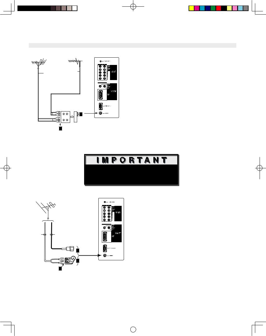
Connecting an Antenna or Wall Outlet Cable
Note: The TV side panel and connections shown here are for reference only and may vary by model.
|
|
Separate UHF and VHF Antennas |
|
||
|
|
|
|
|
|
|
|
(Figure 1) |
1.Connect the UHF and VHF antenna leads to the UHF/VHF combiner.
2.Push the combiner onto ANT on the TV side panel.
|
|
|
|
|
|
UHF/VHF combiners are not provided with
the TV. They are available at most electronic stores.
Note: This TV will only be able to provide an analog signal through ANT on the TV side panel.
Figure 1. Connecting separate UHF and VHF
antennas.
Note: See page 5 for Outdoor Antenna Grounding
 Additionalconnectioncablesarenotprovided withtheTV. Theyshouldbeavailableat mostelectronicstores.
|
Twin Lead Antenna, Coaxial Lead |
|
Antenna, or Wall Outlet Cable |
|
(Figure 2) |
|
For antenna with twin flat leads: |
|
|
|
|
||
|
||
|
|
1.Connect the 300Ohm twin leads to the transformer.
2.Push the 75Ohm side of the transformer onto ANT on the TV side panel.
300Ohm to 75Ohm matching transformers are not provided with the TV. They are available at most electronic stores.
Figure 2. Connecting twin lead antenna, coaxial lead antenna, or wall outlet cable.
Note: See page 5 for Outdoor Antenna Grounding
For cable or antenna with coaxial lead:
3.Connect the incoming cable to ANT on the TV side panel.
Note: This TV will only be able to provide an analog signal through ANT on the TV side panel.
14
LT2240_LT3040_OG_v6.ind14 |
|
|
04.1.21, 4:02 PM |
|
|
||
|
|
|
|
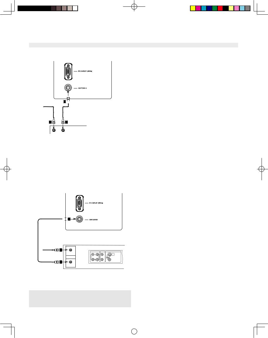
Connecting an Antenna to a Cable Box or VCR
Note: The TV side panel and connections shown here are for reference only and may vary by model.


|
|
|
|
|
|
|
|
|
Figure 3. Connecting the cable box.
Cable Box
(Figure 3)
1.Connect the incoming cable to ANT on the TV side panel.
NOTE: If your cable box has separate audio/video outputs, please see Composite Video with Audio or S-Video with Audio, page 16 (Figure 6).
Note: See page 5 for Outdoor Antenna grounding.
|
Antenna or Wall Outlet Cable |
|
|
|
(Figure 4) |
|
1. Connect the incoming cable to ANT on the TV |
|
side panel. |


|
|
|
|
|
|
|
|
|
|
|
|
|
||
|
|
|
|
|
|
|
|||
|
|
|
|
|
|
|
|
||
|
|
|
|
|
|
|
|
|
|
|
|
|
|
|
NOTE: If your cable box has separate audio/video outputs, please see Composite Video with Audio or S-Video with Audio, page 16 (Figure 6).
Figure 4. Connecting the VCR with antennas or wall outlet cable.
Note: If you have a digital cable box, refer to your Digital Cable Box owner’s guide for instructions on optimal connections to this TV.
15
LT2240_LT3040_OG_v6.ind15 |
|
|
04.1.21, 4:02 PM |
|
|
||
|
|
|
|
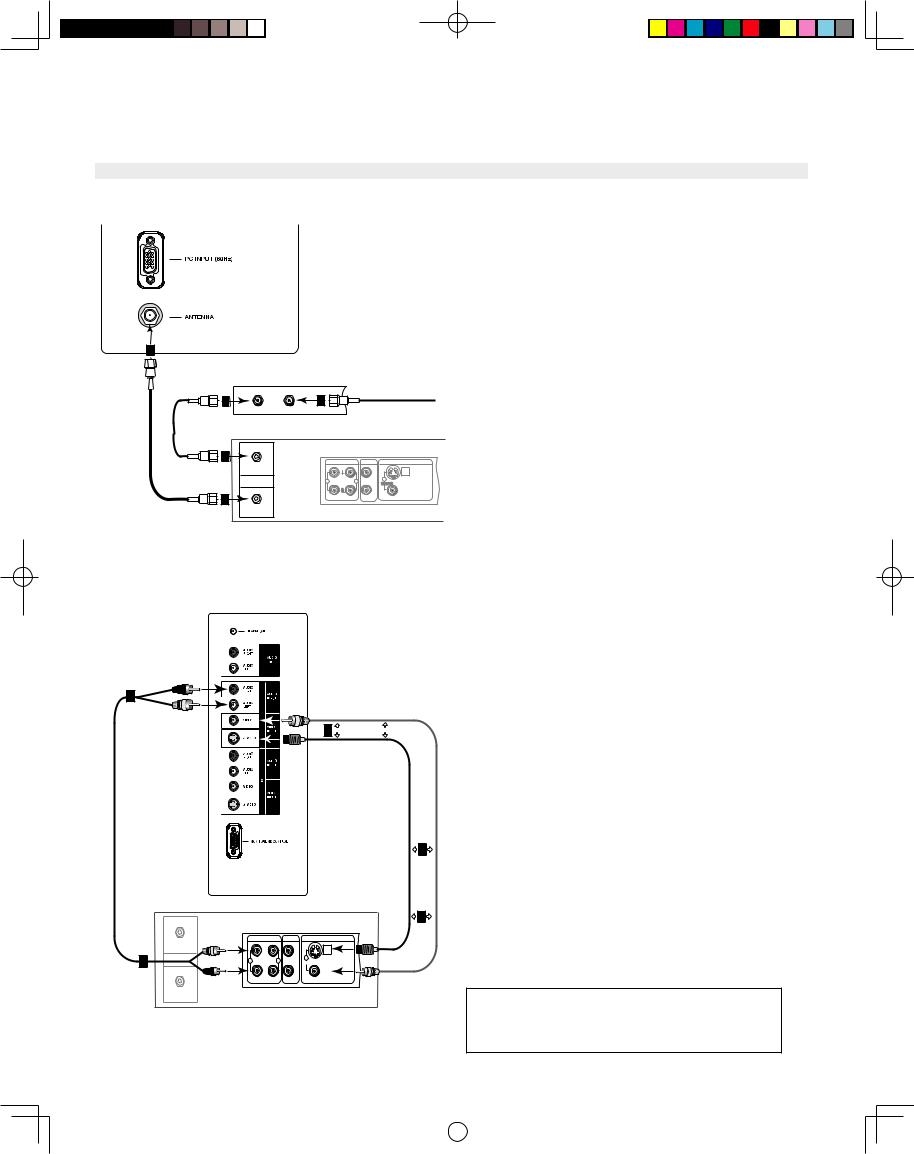
Connecting an Antenna to a Cable Box and VCR, Connecting Audio/Video to the Cable Box or VCR
Note: The TV side panel and connections shown here are for reference only and may vary by model.
|
|
|
|
|
|
|
|
|
|
|
|
||
|
|
|
|
|
|||
|
|
|
|
|
|
||
|
|
|
|
|
|
|
|
|
|
|
|
Figure 5. Connecting the VCR with cable box.
|
|
|
|
|
|
|
|
|
|
|
|
|
|
|
|
|
|
|
|
|
|
|
|
|
|
|
|
|
|
|
|
|
|
|
|
|
|
|
|
|
|
|
|
|
|
|
|
|
|
|
|
||
|
|
|
|
|
|
|
|
|
|
|
|
|
|
|
|
|
|
|
|
|
|||
|
|
|
|
|
|
|
|
|
|||
|
|
|
|
||
|
|
|
|
|
|
|
|
|
|
||
|
|
|
|
|
|
Figure 6. Connecting the VCR Audio/Video.
16
Cable Box
(Figure 5)
1.Connect the incoming cable to ANT on the TV side panel.
NOTE: For best performance, please see Composite Video with Audio or S-Video with Audio, below.
Composite Video with Audio or S-
Video with Audio (Recommended)
(Figure 6)
1.Connect a video or a S-Video cable from VIDEO OUT on the VCR back panel to VIDEO or S-VIDEO, INPUT-1 or INPUT-2 on the TV side panel.
2.Connect a set of audio cables from AUDIO OUT on the VCR back panel to AUDIO INPUT-1 or INPUT-2 on the TV side panel.
•The red cable connects to the R (right) channel
•The white cable connects to the L (left) channel
If your VCR is mono (non-stereo), connect only the white (left) cable.
You may connect to the S-VIDEO or VIDEO terminal but not to both.
LT2240_LT3040_OG_v6.ind16 |
|
|
04.1.21, 4:02 PM |
|
|
||
|
|
|
|

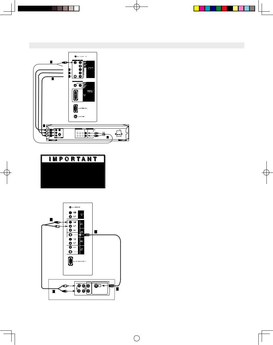
Connecting an Audio Receiver
Note: The TV side panel and connections shown here are for reference only and may vary by model.
Stereo Audio System
(recommended for shelf units or A/V receivers without digital audio inputs)
(Figure 7)
1.Connect the audio cables from AUDIO OUTPUT on the TV side panel to TV IN or AUX IN terminals on the back of the audio system.
•The red cable connects to the R (right) channel
•The white cable connects to the L (left) channel
2.Turn off the TV’s speakers through the AUDIO/ VIDEO SETTINGS Menu, page 50.
3.Set the audio system’s input to the TV or AUX position to hear the TV’s audio through your stereo system.
 Additionalconnectioncablesarenotprovided withtheTV. Theyshouldbeavailableatmost electronicstores.


|
|
|
|
|
|
|
|
|
|
|
|
|
|
|
|
|
|
|
|
|
|
||
|
|
|
|
|
|
|
|
Figure 7. Connecting the Stereo Audio System.
 ThesetypesofaudioconnectiondoNOTsupport multi-channeldigitalaudio. Pleaserefertoyour otherdevicesOwner’sGuidetoverify.
A/V Receiver |
|
||
|
|
||
|
|
|
|
(Figure 8) |
|
|
|
|
|
||
1. |
Connect either a video cable or a S-Video cable |
|
|
|
(but not both) from VIDEO MONITOR OUT on |
|
|
|
the back of the A/V receiver to VIDEO INPUT-1 |
|
|
|
or INPUT-2 on the TV side panel. |
|
|
|
|
|
|
|
|
|
|
|
|
|
|
2. |
Connect a set of audio cables from AUDIO |
|
|
|
|
||
|
OUTPUT on the TV side panel to AUDIO TV |
|
|
|
|
||
|
|
|
|
|
IN on the back of the A/V receiver. |
|
|
|
|
||
|
|
|
|
• The red cable connects to the R (right) channel
• The white cable connects to the L (left) channel
Figure 8. Connecting the A/V Receiver.
Note: Please see your A/V receiver Owner’s Guide for more detailed connections.
17
LT2240_LT3040_OG_v6.ind17 |
|
|
04.1.21, 4:02 PM |
|
|
||
|
|
|
|
Connecting a DVD Player or Other S-Video Device
Note: The TV side panel and connections shown here are for reference only and may vary by model.
|
|


|
|
|
|
|
|
|
|
|
|
|
|
|
|
|
|
|
|
|
|
|
|
|
|
|
|
|
|
|
|
||
|
|
|
|
|
|
|
|
|
|
|
|
|
|
|
|
|
|
|
|
|
|
|
|
|
|
|
|
|
|
|
|
|
|
|
|
|
|
|
|
|
|
|
|
|
|
||
|
|
|
|
|
|
|
|
|
|
|
|
|
|
|
DVD Player/Video Game with
Component Video
(Figure 9)
1.Connect the Component Video cables from (YCbCr or YPbPr) VIDEO OUT on the back of the DVD player to COMPONENT (1 or 2) on the TV side panel. The correct connections are:
A.Y to Y
B.Cb or Pb to Pb
C.Cr or Pr to Pr
2.Connect a set of audio cables from AUDIO OUT
on the back of the DVD player to COMPONENT AUDIO Input (1 or 2) on the TV side panel.
Figure 9. Connecting a DVD Player with Component Video.
 SeeAppendixB,page58,forcomponentvideo
signalcompatibilityinformation.
 Fordigitalaudioconnections,seeyourDVD
andA/VreceiverOwner’sGuides.
|
|
|
|
|
|
|
|
|
|
|
|
|
|
|
|
||
|
|
|
|
|
|
|
|
|
|
|
|
|
|
|
|||
|
|
Figure 10. Connecting an S-Video Device.
•The red cable connects to the R (right)channel
•The white cable connects to the L (left) channel
NOTE: Some video game systems support component connections. Please refer to your video game console Owner’s Guide.
NOTE: If your DVD player supports progressive scan playback, be sure to set your player accordingly. Please refer to your DVD player’s Owner’s Guide.
Other S-Video Device
(Figure 10)
1.Connect a S-Video cable from VIDEO OUT on the device back panel to VIDEO INPUT-1 or INPUT-2 on the TV side panel.
2.Connect a set of audio cables from AUDIO OUT on the device back panel to AUDIO INPUT-1 or INPUT-2 on the TV side panel.
•The red cable connects to the R (right) channel
•The white cable connects to the L (left) channel
If your S-Video Device is mono (non-stereo), connect only the white (left) cable.
18
LT2240_LT3040_OG_v6.ind18 |
|
|
04.1.21, 4:03 PM |
|
|
||
|
|
|
|
Connecting a DTV Receiver
Note: The TV side panel and connections shown here are for reference only and may vary by model.
 SeeAppendixB,page58for componentvideo signalcompatibilityinformation.
 Fordigitalaudioconnections,seeyourDTV receiverandA/VreceiverOwner’sGuides.
DTV Receiver with Component
Video Connections (Recommended)
(Figure 11)
1.Connect the outside antenna cable, or satellite to ANT or SATELLITE IN on the DTV receiver (see your DTV receiver owner’s guide for instructions and cable compatibility).
2.If your DTV receiver has a built-in terrestrial tuner, connect the incoming terrestrial antenna to ANT on the DTV receiver. If your DTV receiver does not have a built-in terrestrial tuner, this TV will only be able to provide an analog signal through ANT on the TV side panel.


3.Connect the RCA-type cables from the DTV receiver outputs to the TV side panel. Component (1 or 2) may be used for 480i, 480p, 720p or 1080i components.
4.Connect the L (left) and R (right) audio cables from the DTV receiver to AUDIO INPUT-1 or INPUT-2 on the TV back panel.
5.To utilize the benefits of a digital A/V receiver, connect your DTV receiver’s digital audio out to a digital input on your digital A/V receiver.
|
|
|
|
|
|
|
|
|
|
|
|
|
|
|
|
|
|
|
|
|
|
|
|
|
|
|
|
|
|
|
|
|
|
|
|
||
|
|
|
|
|
|
|
||
|
|
|
|
|
|
|
|
|
|
|
|
|
|
|
|
|
|
|
|
|
|
|
|
|
|
|
|
|
|
|
|
|
|
|
|
|
|
|
|
|
|
|
|
|
|
|
|
|
|
|
|
|
|
|
|
|
|
|
|
|
|
|
|
|
|
|
|
|
|
|
|


Figure 11. Connecting a DTV receiver with component Video Connections.
19
LT2240_LT3040_OG_v6.ind19 |
|
|
04.1.21, 4:03 PM |
|
|
||
|
|
|
|
This page intentionally left blank
20
LT2240_LT3040_OG_v6.ind20 |
|
|
04.1.21, 4:03 PM |
|
|
||
|
|
|
|
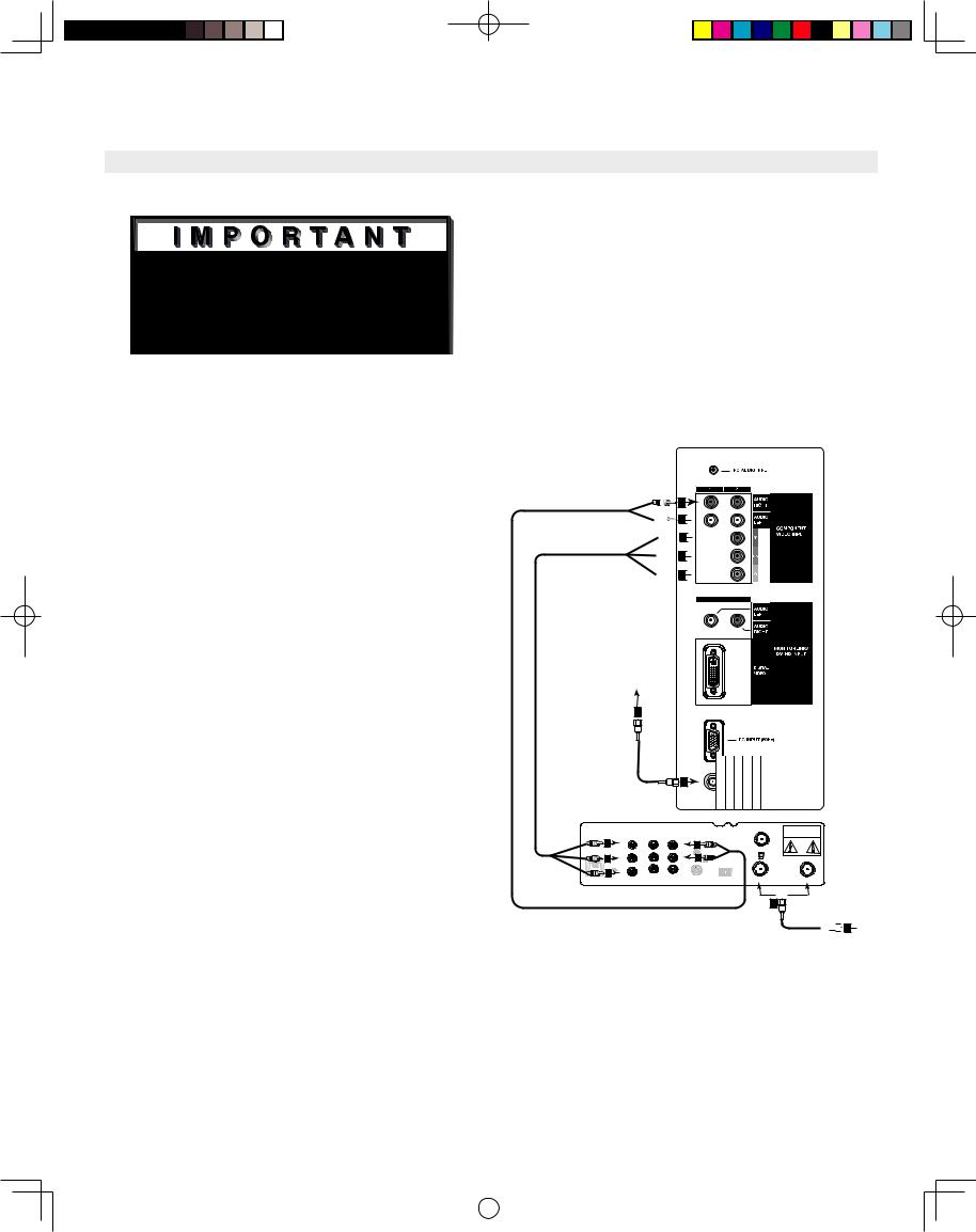
Connecting MonitorLink™ or a Computer
Note: The TV side panel and connections shown here are for reference only and may vary by model.
MonitorLink Connection
(Figure 14)
1.Connect a MonitorLink/DVI cable from the TV side panel to the Mitsubishi HD Receiver/Controller back panel.
2.Connect the MonitorLink Control/RS-232 cable from the TV side panel to the Mitsubishi HD Receiver/ Controller back panel.
3.Connect the L (left) and R (right) audio cables from the HDTV receiver to AUDIO LEFT and AUDIO RIGHT on the MonitorLink section of the TV side panel.
NOTE: The MonitorLink/DVI and 9-pin RS-232 cables can be found at your local electronics
store. Please refer to www.mitsubishi-tv.com for more information on RS-232C control.
CAUTION: To assure continued FCC compliance, the user must use a shielded video interface cable with bonded ferrite cores at each end, when using the MonitorLink/DVI input.
|
|
|
|
|
|
|
|
|
|
|
|
|
|
|
|
|
|
|
|
|||||||
|
|
|
|
|
|
|
|
|
|
|
|
|
|
|
|
|
|
|
|
|
|
|
|
|
|
|
|
|
|
|
|
|
|
|
|
|
|
|
|
|
|
|
|
|
|
|
|
|
|
|
|
|
|
|
|
|
|
|
|
|
|
|
|
|
|
|
|
|
|
|
|
|
|
|
|
|
|
|
|
|
|
|
|
|
|
|
|
|
|
|
|
|
|
|
|
|
|
|
|
|
|
|
|
|
|
||
|
|
|
|
|
|
|
|
|
|
|
|
|
|
|
|
|
|
|
|
|
|
|
|
|
|
|
|
|
|
|
|
|
|
|
|
Figure 14. Connecting MonitorLink


|
|
|
|
Figure 15. Connecting Computer
Connecting a Computer
(Figure 15)
• Your Mitsubishi TV supports VGA, SVGA, XGA, and WXGA PC resolutions only. (60Hz only)
1. Connect a Mini D-sub 15-pin (RGB) cable from the TV side panel to PC or Macintosh® back panel.
2. Connect a PC Audio Cable (or 1/8” stereo mini jack cable) from the TV side panel to PC or Macintosh back panel.
NOTE: The Mini D-sub 15-pin (RGB) and 1/8” (3.5mm) stereo mini jack cables can be found at your local electronics store.
NOTE: Connecting your computer to this TV will allow you to display your computer’s images. Since this monitor is widescreen (16:9 aspect ratio), the display configuration will vary depending on which video card or driver(s) you use. You may also need to use a Macintosh adapter when connecting to some Macintosh computers.
21
LT2240_LT3040_OG_v6.ind21 |
|
|
04.1.21, 4:03 PM |
|
|
||
|
|
|
|
 Loading...