


 Loading...
HARDWARE MANUAL
FX1S SERIES PROGRAMMABLE CONTROLLERS

FX2NC Series Programmable Controllers
Foreword
•This manual contains text, diagrams and explanations which will guide the reader in the correct installation and operation of the FX1S Series Programmable Controllers. It should be read and understood before attempting to install or use the unit.
•Further information can be found in the FX Series Programming Manual II.
•If in doubt at any stage of the installation of an FX1S Series Programmable Controller always consult a professional electrical engineer who is qualified and trained to the local and national standards which apply to the installation site.
•If in doubt about the operation or use of FX1S Series Programmable Controller please consult the nearest Mitsubisi Electric distributor.
•This manual is subject to change without notice.

FX1S Series Programmable Controllers
FX1S Series Programmable Controllers
Hardware Manual
Manual number : JY992D83901
Manual revision : B
Date |
: April 2000 |

FX1S Series Programmable Controllers
Guidelines for the Safety of the User and Protection of the FX1S.
This manual provides information for the use of the FX1S. The manual has been written to be used by trained and competent personnel. The definition of such a person or persons is as follows:
a)Any engineer who is responsible for the planning, design and construction of automatic equipment using the product associated with this manual, should be of a competent nature, trained and qualified to the local and national standards required to fulfill that role. These engineers should be fully aware of all aspects of safety with regards to automated equipment.
b)Any commissioning or service engineer must be of a competent nature, trained and qualified to the local and national standards required to fulfill that job. These engineers should also be trained in the use and maintenance of the completed product. This includes being completely familiar with all associated documentation for said product. All maintenance should be carried out in accordance with established safety practices.
c)All operators of the completed equipment should be trained to use that product in a safe and coordinated manner in compliance to established safety practices. The operators should also be familiar with documentation which is connected with the actual operation of the completed equipment.
Note : The term ‘completed equipment’ refers to a third party constructed device which contains or uses the product associated with this manual.
ii
FX1S Series Programmable Controllers
Note’s on the Symbology Used in this Manual
At various times through out this manual certain symbols will be used to highlight points of information which are intended to ensure the users personal safety and protect the integrity of equipment. Whenever any of the following symbols are encountered its associated note must be read and understood. Each of the symbols used will now be listed with a brief description of its meaning.
Hardware Warnings
1) Indicates that the identified danger WILL cause physical and property damage.
2) Indicates that the identified danger could POSSIBLY cause physical and property damage.
3) Indicates a point of further interest or further explanation.
Software Warnings
4) Indicates special care must be taken when using this element of software.
5) Indicates a special point which the user of the associate software element should be aware.
6) Indicates a point of interest or further explanation.
iii

FX1S Series Programmable Controllers
•Under no circumstances will Mitsubishi Electric be liable responsible for any consequential damage that may arise as a result of the installation or use of this equipment.
•All examples and diagrams shown in this manual are intended only as an aid to understanding the text, not to guarantee operation. Mitsubishi Electric will accept no responsibility for actual use of the product based on these illustrative examples.
•Owing to the very great variety in possible application of this equipment, you must satisfy yourself as to its suitability for your specific application.
iv

FX1S Series Programmable Controllers |
Table of Contents |
Table of Contents
Guideline .......................................................................................................................... ii
1. Introduction ......................................................................................... |
1-1 |
||
1.1 |
Model Name..................................................................................................... |
1-3 |
|
1.2 |
World Specification .......................................................................................... |
1-4 |
|
1.3 |
Serial Number .................................................................................................. |
1-4 |
|
1.4 |
Configuration.................................................................................................... |
1-5 |
|
|
1.4.1 |
Unit Configuration .................................................................................... |
1-6 |
1.4.2 |
Rules for Expansion ............................................................................................ |
1-7 |
|
1.5 |
EEPROM Backup ............................................................................................ |
1-7 |
|
2. |
Terminal layouts.................................................................................. |
2-1 |
|
|
2.1 |
Relay Output Controllers.................................................................................. |
2-1 |
|
2.2 |
Transistor Output Controllers .......................................................................... |
2-2 |
3. |
Installation notes ................................................................................. |
3-1 |
|
|
3.1 |
Product Outline ................................................................................................ |
3-2 |
|
3.2 |
FX1S RUN/STOP Control................................................................................. |
3-3 |
|
3.3 |
General Specifications ..................................................................................... |
3-4 |
|
3.4 |
PLC Mounting Arrangements........................................................................... |
3-5 |
|
3.5 |
DIN Rail Mounting............................................................................................ |
3-6 |
|
3.6 |
Termination of Screw Terminals ...................................................................... |
3-6 |
v

FX2NC Series Programmable Controllers Contents.
4. Power supply....................................................................................... |
4-1 |
|
4.1 |
Wiring Cautions................................................................................................ |
4-1 |
4.2 |
Wiring Techniques ........................................................................................... |
4-1 |
4.3 |
Power Supply................................................................................................... |
4-1 |
4.4 |
Power Supply Characteristics .......................................................................... |
4-3 |
4.5 |
Earth/Grounding............................................................................................... |
4-4 |
5. Inputs |
.................................................................................................. |
5-1 |
5.1 24V DC Input Specifications ............................................................................ |
5-1 |
|
5.1.1 |
Typical Wiring ...................................................................................................... |
5-2 |
5.1.2 |
Input Circuit Connection ...................................................................................... |
5-3 |
5.1.3 ............................................................. |
Diodes and Inputs Connected in Series; |
5-3 |
5.1.4 ....................................................... |
Resistors and Inputs Connected in Parallel; |
5-4 |
6. Outputs |
............................................................................................... |
6-1 |
|
6.1 |
Output Specification......................................................................................... |
6-1 |
|
6.1.1 |
Relay Output Example ........................................................................................ |
6-2 |
|
6.1.2 |
Reliability Tests .................................................................................................. |
6-3 |
|
6.1.3 |
Response Times ................................................................................................. |
6-3 |
|
6.2.2 |
Transistor Output Example.................................................................................. |
6-4 |
|
6.3.1 |
Japanese Model Transistor Output ..................................................................... |
6-4 |
|
6.2 |
Applying Safe Loads ........................................................................................ |
6-5 |
|
vi

FX1S Series Programmable Controllers Table of Contents
7. Diagnostics.......................................................................................... |
7-1 |
||
7.1 |
Preliminary Checks .......................................................................................... |
7-1 |
|
7.1.1 |
ERROR LED ON (CPU ERROR) ........................................................................ |
7-2 |
|
7.2 |
Common errors ................................................................................................ |
7-3 |
|
7.3 |
Maintenance .................................................................................................... |
7-3 |
|
7.4 |
Operation and Error Flags ............................................................................... |
7-4 |
|
7.5 |
Error Registers................................................................................................. |
7-5 |
|
7.6 |
Error Codes...................................................................................................... |
7-7 |
|
7.7 |
Instruction List.................................................................................................. |
7-8 |
|
7.8 |
Device List ..................................................................................................... |
7-11 |
|
vii

FX2NC Series Programmable Controllers |
Contents. |
viii
FX1S Series Programmable Controller |
Introduction 1 |
1 |
Introduction |
2
 Terminal Layouts
3
 Installation Notes
4
 Power Supply
5
 Inputs
6
 Outputs
7
 Diagnostics

FX1S Series Programmable Controller |
Introduction 1 |

FX1S Series Programmable Controller |
Introduction 1 |
1.Introduction
This manual covers the hardware installation instructions for the FX1S Series Programmable Logic Controller.
Table 1.1 : Relay Output Units
|
INPUT |
OUTPUT |
POWER |
DIMENSIONS |
MASS |
|||||
MODEL |
|
|
|
|
(WEIGHT) |
|||||
QTY |
TYPE |
QTY |
TYPE |
SUPPLY |
mm (inches) |
|||||
|
kg (lbs) |
|||||||||
|
|
|
|
|
|
|
|
|
||
|
|
|
|
|
|
|
|
|
|
|
FX1S-10MR-ES/UL |
6 |
|
4 |
|
|
60 |
|
|
0.3 (0.66) |
|
FX1S-14MR-ES/UL |
8 |
24V DC |
6 |
|
|
(2.4) |
|
|
||
|
|
|
|
|
||||||
|
|
|
|
85 - 264 |
|
90 |
75 |
|
||
|
|
|
|
75 |
0.4 |
|||||
FX1S-20MR-ES/UL |
12 |
Sink / |
8 |
Relay |
||||||
VAC |
(3.0) |
(3.5) |
(3.0) |
(0.88) |
||||||
|
|
Source |
|
|
||||||
|
|
|
|
|
|
|
|
|
||
FX1S-30MR-ES/UL |
16 |
|
14 |
|
|
100 |
|
|
0.45 |
|
|
|
|
(3.9) |
|
|
(0.99) |
||||
|
|
|
|
|
|
|
|
|||
|
|
|
|
|
|
|
|
|
|
|
Table 1.2 : Transistor Output Units
|
INPUT |
|
OUTPUT |
POWER |
DIMENSIONS |
MASS |
|||||
MODEL |
|
|
|
|
|
(WEIGHT) |
|||||
QTY |
TYPE |
QTY |
TYPE |
SUPPLY |
mm (inches) |
||||||
|
kg (lbs) |
||||||||||
|
|
|
|
|
|
|
|
|
|
||
|
|
|
|
|
|
|
|
|
|
|
|
FX1S-10MT-ESS/UL |
6 |
|
4 |
|
|
|
60 |
|
|
0.3 |
|
FX1S-14MT-ESS/UL |
8 |
24V DC |
6 |
|
|
|
(2.4) |
|
|
(0.66) |
|
|
|
|
|
Transistor |
85 - 264 |
|
90 |
75 |
|
||
|
|
|
|
75 |
0.4 |
||||||
FX1S-20MT-ESS/UL |
12 |
Sink / |
8 |
|
|||||||
|
(Source) |
VAC |
(3.0) |
(3.5) |
(3.0) |
(0.88) |
|||||
|
|
Source |
|
|
|||||||
|
|
|
|
|
|
|
|
|
|
||
FX1S-30MT-ESS/UL |
16 |
|
14 |
|
|
100 |
|
|
0.45 |
||
|
|
|
(3.9) |
|
|
(0.99) |
|||||
|
|
|
|
|
|
|
|
|
|||
|
|
|
|
|
|
|
|
|
|
|
|
1-1
FX1S Series Programmable Controller |
Introduction 1 |
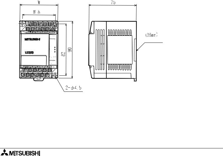
Figure 1.1: FX1S Outline Drawing
DIN Rail
The distance between the vertical centerlines is 8mm (0.31”) less than the width of the unit Please see previous page for each model’s width measurement.
1-2
FX1S Series Programmable Controller |
Introduction 1 |
1.1Model name
F X 1 S - 1 4 M T- E S S / U L
A)
B) F)
C) E)
D)
Table 1.3 : Model Table
A)PLC type : FX1S
B)Total number of I / O channels
Unit type
C)
MMPU - main unit
Output type
D)R Relay
T Transistor
|
|
Features |
||
|
|
|
||
|
Omit |
AC, Japanese specification |
||
|
|
|
|
|
|
D |
24V |
DC Japanese specification |
|
|
|
|
|
|
|
DS |
24V |
DC World specification |
|
E) |
|
|
|
|
DSS |
24V |
DC World specification, DC source transistor |
||
|
||||
|
|
|
||
|
ES |
AC Power Supply World specification |
||
|
|
|
||
|
ESS |
AC Power Supply World specification, DC source |
||
|
|
transistor |
||
|
UA1 |
AC Power Supply, AC inputs |
||
|
|
|
||
F) |
UL |
CE,UL registered product |
||
|
|
|
|
|
1-3

FX1S Series Programmable Controller |
Introduction 1 |
1.2World Specification
Table 1.4 : World / Japanese Specifications
Input |
World spec models : SINK / SOURCE |
Sink / Source |
Japanese models : ALWAYS SINK |
|
|
Outputs |
World spec models : ALWAYS SOURCE |
Transistor |
Japanese models : ALWAYS SINK |
|
|
1.3Serial Numbers
S E R I A L N O. : 9 X 3 2 6 7 |
||||||||||||
1) |
|
|
|
|
|
|
|
|
|
|
3) |
|
|
|
|
|
|
|
|
|
|
|
|
|
|
e.g. |
2) |
|
|
|
|
|
|
|
|
|
|
|
9=1999 |
|
|
|
|
|
|
|
|
|
|
||
|
|
|
|
|
|
|
|
|
|
|
||
1 - 9 = Jan - Sept |
||||||||||||
0=2000 |
||||||||||||
X |
= Oct |
|||||||||||
|
||||||||||||
|
Y |
= Nov |
||||||||||
|
Z |
= Dec |
||||||||||
Table 1.5 : Notes on Serial Numbers
1)Production year
2)Production month
3)Production serial number
1-4
FX1S Series Programmable Controller |
Introduction 1 |
1.4Configuration
Figure 1.2: Schematic system
|
FX1N-5DM |
|
|
|
|||
|
FX1N-EEPROM-8L |
|
|
FX1S-10MR-ES/UL |
|||
|
|
|
|
|
|
|
|
|
|
|
B |
1 |
FX1S-14MR-ES/UL |
||
|
|
|
|
|
|
|
FX1S-20MR-ES/UL |
|
1 |
|
|
|
|
||
|
|
|
|
|
FX1S-30MR-ES/UL |
||
|
|
|
|
|
|||
|
FX1N-232-BD |
|
|
|
|||
|
FX1N-422-BD |
|
|
FX1S-10MT-ESS/UL |
|||
|
FX1N-485-BD |
|
|
|
|||
|
|
|
|
|
|||
|
FX1N-CNV-BD |
2 |
FX1S-14MT-ESS/UL |
||||
|
|
|
FX1S-20MT-ESS/UL |
||||
|
FX1N-8AV-BD |
|
|
||||
|
|
|
FX1S-30MT-ESS/UL |
||||
|
|
|
C |
|
|
||
|
|
|
|
|
|
||
|
|
|
|
|
|
|
|
A
3
FXON-232ADP* FXON-485ADP* *used with FX1N-CNV-BD D
RS 422/RS 232 CONVERTER FX-232AW(C)
SCO*
E
MELSEC MEDOC
FX-PCS/AT-EE
MELSEC MEDOC PLUS
FX-PCS/WIN-E F
FX-10DU-E FX-40DU-ES FX-20DU-E FX-40DU-TK -ES FX-25DU-E FX-50DU-TKS-E FX-30DU-E
F930GOT F940GOT |
|
FX-10DM-E |
G |
|
FX-10P-E FX-20P-E
A6 GPP/PHP + FX-A6GPP-E- KIT
H
1-5

FX1S Series Programmable Controller |
Introduction 1 |
1.4.1Unit accessories
Table 1.6 : Configuration Notes
A |
FX1S Controller Main Body |
|
|
B |
FX1N Memory Cassette or Display Unit |
|
|
C |
FX1N Expansion Boards |
|
|
D |
FX0N Network Adaptors |
|
|
E |
Programming Cables |
|
|
F |
Programming Software |
|
|
G |
HMI Devices, F900 GOT and FX-DU Series |
|
|
H |
Dedicated Programming Tools |
|
|
Table 1.7 : Connection Ports
1Memory Port
2Extension Board Port
3Programming Port
1-6

FX1S Series Programmable Controller |
Introduction 1 |
1.4.2Rules for Expansion
The FX1S Series can:
•Use one expansion unit or board per square B, C, and G concurrently.
•The FX1S can supply 400mA at 24V DC.
The FX1S cannot:
-Be expanded by the use of Special Funcion Blocks.
-Supply a 5V DC service supply.
-Use FX1N-422-BD + FX-2PIF.
-Use the FX1N-5DM and the FX-10DM concurrently.
-Use more than one FX-10DM at the same time. For example, the configuration FX-10DM + (FX1N-422-BD + FX-10DM) is not allowed.
1.5EEProm Backup Data
FX1S existing data will be kept for 5 minutes during power down before the data is lost.
The capacitor backed memory will retain programs for 10 days and the capacitor requires 30 minutes to recharge upon powerup.
1-7

FX1S Series Programmable Controller |
Introduction 1 |
1-8
FX1S Series Programmable Controllers
1
 Introduction
2
 Terminal Layouts
3
 Installation Notes
4
 Power Supply
5
 Inputs
6
 Outputs
7
 Diagnostics
Loading...