


MITSUBISHI ELECTRIC AUTOMATION, INC
UNINTERRUPTIBLE POWER SUPPLY SYSTEM
9800A SERIES
OWNERS / TECHNICAL MANUAL
(For parallel operation possible model only.)
Revision 2.01 Feb. 4, 04
ALN-H0776
MITSUBISHI ELECTRIC 9800A SERIES UPS

MITSUBISHI |
9800A SERIES UPS |
Page Number: |
ELECTRIC |
OWNERS / TECHNICAL MANUAL |
i |
Preface
MITSUBISHI ELECTRIC 9800A SERIES UPS

|
MITSUBISHI |
9800A SERIES UPS |
Page Number: |
|
ELECTRIC |
OWNERS / TECHNICAL MANUAL |
ii |
|
|
TABLE OF CONTENTS |
|
LIST OF TABLES ............................................................................................... |
|
iii |
|
LIST OF FIGURES ............................................................................................ |
|
iv |
|
HOW TO USE THIS MANUAL |
........................................................................... |
v |
|
1.0 |
INTRODUCTION ....................................................................................... |
|
1-1 |
1.1 |
GENERAL .................................................................................................. |
|
1-3 |
1.2 |
DEFINITIONS ............................................................................................ |
|
1-4 |
1.3 |
OPERATION OVERVIEW ......................................................................... |
1-5 |
|
1.4 |
SPECIFICATIONS .................................................................................... |
|
1-12 |
2.0 |
OPERATION CONTROLS AND INDICATORS ........................................ |
2-1 |
|
2.1 |
LED DISPLAY ........................................................................................... |
|
2-2 |
2.2 |
EPO BUTTON ........................................................................................... |
|
2-2 |
2.3 |
LIQUID CRYSTAL DISPLAY ..................................................................... |
2-3 |
|
2.4 |
EXTERNAL SIGNAL TERMINAL BLOCK ................................................. |
2-8 |
|
2.5 |
EXTERNAL COMMUNICATION CONNECTOR ....................................... |
2-12 |
|
3.0 |
INSTALLATION AND OPERATION ......................................................... |
3-1 |
|
3.1 |
TRANSPORTATION AND INSTALLATION .............................................. |
3-1 |
|
3.2 |
INSTALLATION PROCEDURE ................................................................. |
3-1 |
|
3.3 |
PROCEDURE FOR CABLE CONNECTIONS ........................................... |
3-2 |
|
3.4 |
OPERATING PROCEDURES ................................................................... |
3-24 |
|
4.0 |
RESPONSE TO UPS FAILURE ................................................................ |
4-1 |
|
5.0 |
PARTS REPLACEMENT |
.......................................................................... |
5-1 |
6.0 |
FAULT CODES ......................................................................................... |
|
6-1 |
7.0 |
WARRANTY & OUT OF WARRANTY SERVICE ..................................... |
7-1 |
|
MITSUBISHI ELECTRIC 9800A SERIES UPS

MITSUBISHI |
9800A SERIES UPS |
Page Number: |
|
ELECTRIC |
OWNERS / TECHNICAL MANUAL |
iii |
|
|
|
List of Tables |
|
Table 1.1 |
Power Specifications ................................................................... |
1-12 |
|
Table 1.2 |
UPS Module Information.............................................................. |
1-12 |
|
Table 1.3 |
Detail of Specifications ................................................................ |
1-13 |
|
Table 1.4 |
Rating of Contactor and Fuses .................................................... |
1-14 |
|
Table 3.1 |
How to Transport and Install the System..................................... |
3-1 |
|
Table 3.2 |
List of UPS Weights (lb.).............................................................. |
3-1 |
|
Table 3.3 |
Maximum Permitted Fault Current............................................... |
3-2 |
|
Table 3.4 |
Recommended Cable Sizes ........................................................ |
3-5 |
|
Table 3.5 |
Crimp Type Compression Lug ..................................................... |
3-6 |
|
MITSUBISHI ELECTRIC 9800A SERIES UPS

MITSUBISHI |
9800A SERIES UPS |
Page Number: |
||
ELECTRIC |
OWNERS / TECHNICAL MANUAL |
|
iv |
|
|
|
List of Figures |
|
|
Figure 1.1 |
Single Line Diagram-Normal Operation.................................................. |
|
1-5 |
|
Figure 1.2 |
Single Line Diagram-Bypass Operation.................................................. |
|
1-6 |
|
Figure 1.3 |
Single Line Diagram-Battery Operation .................................................. |
|
1-7 |
|
Figure 1.4 |
UPS Parts Location ................................................................................ |
|
1-8 |
|
Figure 1.5 |
UPS Parts Location (Continued)............................................................. |
|
1-10 |
|
Figure 1.6 |
External I/F circuit PCB IOAU-04 .......................................................... |
|
1-10 |
|
Figure 2.1 |
Operation/Display Panel ......................................................................... |
|
2-1 |
|
Figure 2.2 |
Main Screen ........................................................................................... |
|
|
2-3 |
Figure 2.3 |
Start/Stop Screen ................................................................................... |
|
2-4 |
|
Figure 2.4 |
PIN Protection Screen ............................................................................ |
|
2-4 |
|
Figure 2.5 |
Bypass Voltage Abnormal Message Screen........................................... |
|
2-4 |
|
Figure 2.6 |
Measurement Screen ............................................................................. |
|
2-4 |
|
Figure 2.7 |
Setup Screen.......................................................................................... |
|
|
2-5 |
Figure 2.8 |
Log Select Screen .................................................................................. |
|
2-5 |
|
Figure 2.9 |
Event Log Screen ................................................................................... |
|
2-5 |
|
Figure 2.10 |
Battery Log Screen ............................................................................... |
|
2-6 |
|
Figure 2.11 |
Main Screen (Battery Operation) .......................................................... |
|
2-6 |
|
Figure 2.12 |
Measurement Screen (Battery Operation) .............................................. |
|
2-6 |
|
Figure 2.13 |
Main Screen (Fault Indication) .............................................................. |
|
2-7 |
|
Figure 2.14 |
Message Screen ................................................................................... |
|
2-7 |
|
Figure 2.15 |
External Signal Terminal Block............................................................... |
|
2-8 |
|
Figure 2.16 |
Control Wiring for External Contacts ...................................................... |
|
2-10 |
|
Figure 2.17 |
Remote "Start" Contact Connections...................................................... |
|
2-11 |
|
Figure 2.18 |
External communication connector......................................................... |
|
2-12 |
|
Figure 3.1 |
UPS Terminal Designation .................................................................... |
|
3-6 |
|
Figure 3.2 |
Diagram of input/output bus bars and terminal blocks .......................... |
|
3-7 |
|
Figure 3.3 |
Diagram of Rectifier Cabinet & Inverter Cabinet Inter-connect ............. |
|
3-19 |
|
Figure 3.4 |
Diagram of Power and Control Wire Connect (Parallel Connection) |
...... 3-21 |
||
Figure 3.5 |
Operation Procedures: Start Up/Shut Down Procedure.......................... |
|
3-24 |
|
MITSUBISHI ELECTRIC 9800A SERIES UPS
MITSUBISHI |
9800A SERIES UPS |
Page Number: |
ELECTRIC |
OWNERS / TECHNICAL MANUAL |
v |
How to use this Manual
This manual is designed for ease of use, giving the user easy and quick reference to information.
This manual uses notice icons to draw attention to the user important information regarding the safe operation and installation of the UPS. The notice icons used in this manual are explained below, and should be taken into account and adhered to whenever they appear in the text of this manual.
Warning: A warning notice icon conveys information provided to protect the user and service personnel against hazards and/or possible equipment damage.
Caution: A caution notice icon conveys information provided to protect the user and service personnel against possible equipment damage.
Note: A Note notice icon indicates when the user should make a reference of information regarding the UPS operation, load status and display status. Such information is essential if Mitsubishi field service group assistance and correspondence is required.
Safety Recommendations: If any problems are encountered while following this manual, Mitsubishi field service group assistance and correspondence is recommended.
MITSUBISHI ELECTRIC 9800A SERIES UPS
MITSUBISHI |
9800A SERIES UPS |
Page Number: |
ELECTRIC |
OWNERS / TECHNICAL MANUAL |
1-1 |
1.0 INTRODUCTION
Your Mitsubishi Uninterruptible Power System (UPS) is designed to provide many years of reliable protection from power failure, brown-outs, line noise, and voltage transients. To ensure optimum performance of the equipment, follow the manufacturer's instructions. This manual contains descriptions required to operate the UPS. Please read this manual carefully and retain it for future reference.
IMPORTANT SAFETY INSTRUCTIONS
RETAIN THESE INSTRUCTIONS
This manual contains important instructions for the 9800A SERIES Uninterruptible Power Supply Systems that should be followed during installation and maintenance of the UPS and batteries.
WARNING 1
Lethal voltages exist within the equipment during operation. Observe all warning and cautions in this manual. Failure to comply may result in serious injury or death. Obtain qualified service for this equipment as instructed.
MITSUBISHI ELECTRIC 9800A SERIES UPS
MITSUBISHI |
9800A SERIES UPS |
Page Number: |
ELECTRIC |
OWNERS / TECHNICAL MANUAL |
1-2 |
WARNING 2
This UPS does not include a Bypass input circuit breaker (MCCB) to protect bypass circuit. The Bypass input circuit breaker (MCCB) is to be field supplied and installed. Recommended Breaker (MCCB)'s Specifications are as follows:
Capacity (kVA) |
Bypass Voltage (Vac) |
Bypass Rating (Aac) |
Breaker (A) |
100 |
480 |
120 |
150 |
|
|
|
|
|
600 |
96 |
125 |
|
|
|
|
150 |
480 |
180 |
225 |
|
|
|
|
|
600 |
144 |
200 |
|
|
|
|
225 |
480 |
271 |
350 |
|
|
|
|
|
600 |
217 |
275 |
|
|
|
|
300 |
480 |
361 |
500 |
|
|
|
|
|
600 |
289 |
400 |
|
|
|
|
375 |
480 |
451 |
600 |
|
|
|
|
|
600 |
361 |
500 |
|
|
|
|
500 |
480 |
601 |
800 |
|
|
|
|
|
600 |
481 |
600 |
|
|
|
|
750 |
480 |
902 |
1200 |
|
|
|
|
|
600 |
722 |
900 |
|
|
|
|
AC input and AC output overcurrent protection and disconnect devices shall be field supplied and installed. The DC output MCCB shall be field supplied and installed. The overcurrent protection device should be installed in the Battery cabinet and rated as indicated in TABLE 1.4.
MITSUBISHI ELECTRIC 9800A SERIES UPS

MITSUBISHI |
9800A SERIES UPS |
Page Number: |
ELECTRIC |
OWNERS / TECHNICAL MANUAL |
1-3 |
1.1GENERAL
The Mitsubishi 9800A SERIES UPS is designed to provide continuous and clean electrical power to a critical load. Additionally the UPS monitors power conditions affecting the load. In the event of an input power failure, the UPS will supply power to the critical load for the specified battery time.
If the input power is not restored promptly, back up power from the UPS battery permits the orderly shutdown of equipment supported by the UPS. The UPS is simple to start-up, operate and maintain.
The 9800A SERIES UPS is available in seven kVA sizes-100, 150, 225, 300, 375, 500 and 750kVA. Specifications for each kVA model appear in Section 1.4. The principles of operation described herein are applicable to all models.
This manual provides an overview of the 9800A SERIES components and their functions. The appearance and purpose of operator controls and indicators is described with procedures for operation, start-up, shutdown and basic maintenance included.
MITSUBISHI ELECTRIC 9800A SERIES UPS

MITSUBISHI |
9800A SERIES UPS |
Page Number: |
ELECTRIC |
OWNERS / TECHNICAL MANUAL |
1-4 |
1.2Definitions
UNINTERRUPTIBLE POWER SUPPLY SYSTEM (UPS) - All components within the UPS Module Cabinet and associated batteries that function as a system to provide continuous, conditioned AC power to a load. This is sometimes referred to as the "System".
UPS MODULE CABINET - The metal enclosure which contains the Rectifier, the Inverter, the Chopper, the Static Transfer Switch, the Internal Bypass line, the operator controls, and the internal control system required to provide specified AC power to a load.
UPS MODULE - The Rectifier and Inverter assemblies which, under the direction of the internal control system and operator controls, provide specified AC power to a load.
RECTIFIER - The UPS components which contain the equipment and controls necessary to convert input AC power to regulated DC power required for battery charging and for supplying power to the Inverter.
INVERTER - The UPS components which contain the equipment and controls necessary to convert DC power from the Rectifier, or the battery, to AC power required by the critical load.
CHOPPER - The UPS components which contain the equipment and controls necessary to charge the battery and supply power to the Inverter from battery.
STATIC TRANSFER SWITCH - The device which connects the critical load to the bypass line when the UPS module cannot supply continuous power.
BYPASS LINE - The line which conducts electricity directly from the input power source to the critical load during Maintenance or whenever the UPS is not completely operational.
INPUT POWER - Power provided by the electrical utility company, or auxiliary generator, which is connected to the UPS for supplying the critical load.
MITSUBISHI ELECTRIC 9800A SERIES UPS
MITSUBISHI |
9800A SERIES UPS |
Page Number: |
ELECTRIC |
OWNERS / TECHNICAL MANUAL |
1-5 |
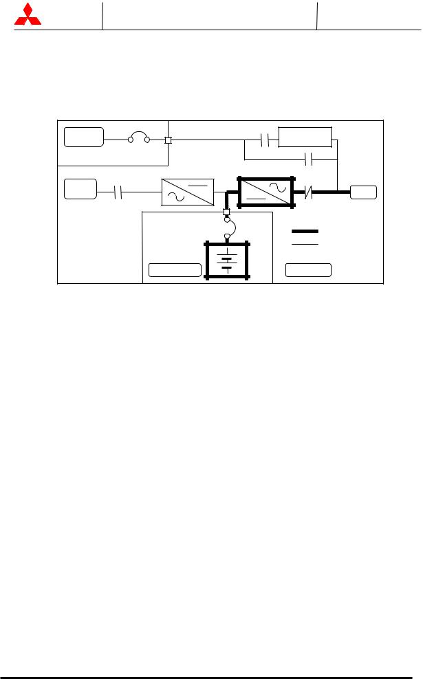
1.3Overview
The UPS provides two power paths between the utility source and the critical load.
Figure 1.1 shows the path for normal operation, with the load powered from the inverter. Figure 1.2 shows the path for bypass operation, with the load supplied through the static bypass line.
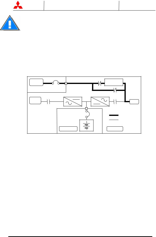
A)Normal operation: Load power supplied by each system UPS inverter.
Figure 1.1 Single Line Diagram - Normal Operation: Load powered by UPS inverters
CB |
|
Static Transfer |
AC Bypass |
|
|
Input |
|
Switch |
User supplied |
CB3 |
|
MCCB |
|
|
RECTIFIER |
INVERTER |
52S |
AC input |
|
Output |
|
|
|
CB1 |
|
52C |
|
CB2 |
Power Flow |
|
|
Not in Use |
Battery cabinet |
|
UPS Module |
During normal operation, the path through the UPS inverters is used to power the load.
Referring to Figure 1.1: For each system UPS, the Input AC power is converted to DC by the Rectifier. DC power is utilized to charge the UPS battery and to provide power to the Inverter. The Inverter converts the DC power to clean AC power to supply the critical load.
The conversion - inversion process eliminates any voltage transients or fluctuations existing in the input power before it reaches the critical load.
The power drawn by the critical load is equally shared between all system UPS.
In the event of a UPS module failure, the critical load power will be continually supplied and shared by all other system UPS.
In the event of a load overcurrent, all system UPS will transfer to bypass without interruption to the critical load.
MITSUBISHI ELECTRIC 9800A SERIES UPS
MITSUBISHI |
9800A SERIES UPS |
Page Number: |
ELECTRIC |
OWNERS / TECHNICAL MANUAL |
1-6 |
The Bypass Input circuit breaker (MCCB) for protection of the UPS and cables are field supplied and field installed. (See WARNING 2 on page 1-2)
B)Bypass Operation: Load Power supplied through each system UPS internal static bypass line.
FIGURE 1.2 Single Line Diagram - Bypass Operation: Load fed through Internal static bypass line.
CB |
|
Static Transfer |
AC Bypass |
|
|
Input |
|
Switch |
User supplied |
CB3 |
|
MCCB |
|
|
RECTIFIER |
INVERTER |
52S |
AC input |
|
Output |
|
|
|
CB1 |
|
52C |
|
CB2 |
Power Flow |
|
|
Not in Use |
Battery cabinet |
|
UPS Module |
Referring to Figure 1.2: The Internal Static Bypass line is a Hard wired line through CB3 and contactor 52S which supplies the critical load with unconditioned input power.
Each system UPS internal static bypass line will equally share the power supplied to the critical load.
The internal static bypass line will route power to the critical load while the UPS module is de-energized during Start-up and before the system is fully operational.
Bypass operation will occur In the event of a load overcurrent, with all system UPS transferring to bypass without interruption to the critical load.
The internal control system determines the operation of the two paths, with the load powered from the inverter being the normal operation.
MITSUBISHI ELECTRIC 9800A SERIES UPS
MITSUBISHI |
9800A SERIES UPS |
Page Number: |
ELECTRIC |
OWNERS / TECHNICAL MANUAL |
1-7 |
C) Battery operation: Load Power supplied by each system UPS battery and inverter.
FIGURE 1.3 Single Line Diagram - Battery Operation
CB |
|
Static Transfer |
AC Bypass |
|
|
Input |
|
Switch |
User supplied |
CB3 |
|
MCCB |
|
|
RECTIFIER |
INVERTER |
52S |
AC input |
|
Output |
|
|
|
CB1 |
|
52C |
|
CB2 |
Power Flow |
|
|
Not in Use |
Battery cabinet |
|
UPS Module |
Referring to Figure 1.3: In the event of AC input source failure or interruption, each system UPS rectifier will de-energize and each UPS battery will immediately discharge and supply DC power to the Inverter to maintain continuous AC power to the load. This operation will continue until:
a)The battery capacity expires and the inverter turns off, or
b)Input power is restored after which the rectifier will power the inverter and critical load and simultaneously recharge the batteries.
A fully charged battery will provide power for the specified time at the rated load, or longer, at a reduced load.
When power is restored after a low battery shutdown, each system UPS Rectifier automatically restarts operation, recharges the batteries and the Inverter is automatically restarted without operator intervention. Load is automatically assumed by the inverter without operator intervention.
The power drawn by the load is equally shared between all system UPS during battery operation.
MITSUBISHI ELECTRIC 9800A SERIES UPS

MITSUBISHI |
9800A SERIES UPS |
Page Number: |
ELECTRIC |
OWNERS / TECHNICAL MANUAL |
1-8 |
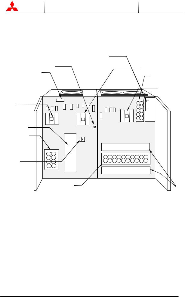
FIGURE 1.4-a UPS Parts Location (100kVA, 150kVA, 225kVA)
UPS module
FRONT VIEW
AC capacitors
Rectifier unit
52S
CB1
FIGURE 1.4-b
|
Inverter |
|
Chopper |
|
unit |
|
DC |
|
capacitors |
|
1. CPM |
|
CB3 |
2. |
External I/F |
|
circuit PCB |
|
IOAU-04 |
3. Grounding Bar
52C
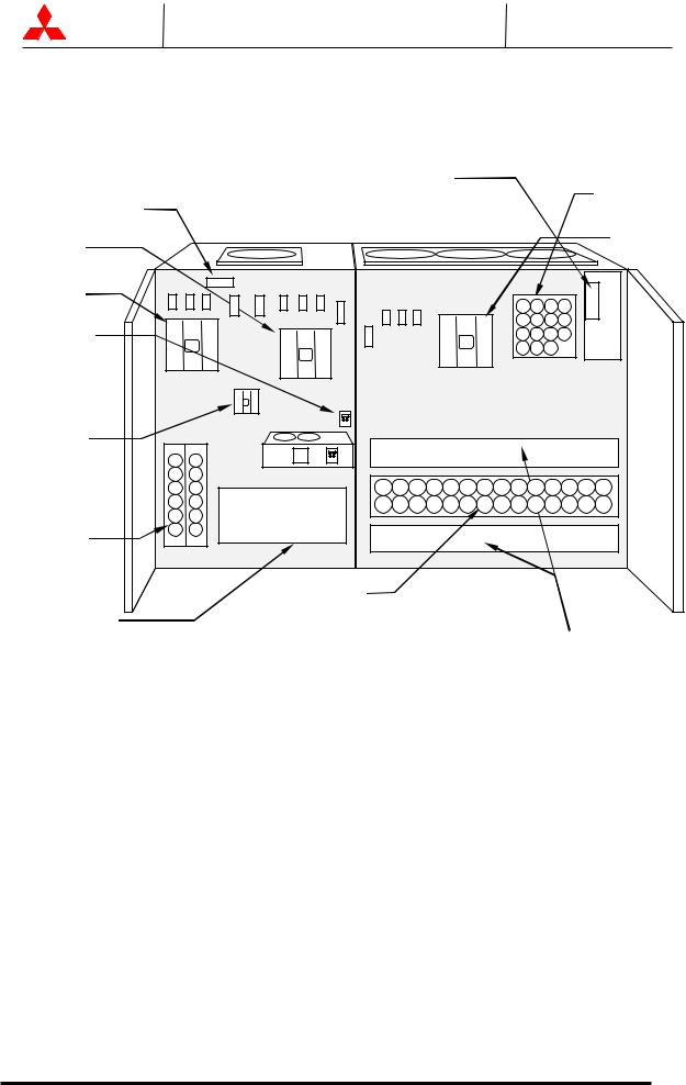
UPS Parts Location (300kVA,375kVA)
UPS module
3. Grounding |
FRONT VIEW |
52S |
|
|
52C |
|
|
Bar |
|
|
|
CB1 |
|
2. |
External I/F |
|
|
|
circuit PCB |
CB3 |
|
|
IOAU-04 |
|
|
|
|
|
|
|
1.CPM |
AC capacitors |
|
|
Inverter |
|
|
|
|
|
|
|
Chopper |
Rectifier |
|
|
unit |
|
|
|
|
unit |
|
|
DC |
|
|
|
capacitors |
MITSUBISHI ELECTRIC 9800A SERIES UPS
MITSUBISHI |
9800A SERIES UPS |
Page Number: |
ELECTRIC |
OWNERS / TECHNICAL MANUAL |
1-9 |
FIGURE 1.4-c UPS Parts Location (500kVA)
UPS module
FRONT VIEW
2. External I/F circuit PCB IOAU-04
1.CPM
4.Grounding Bar
52S
AC capacitors
52C
CB1 |
|
Rectifier |
|
unit |
|
AC capacitors |
|
CB3 |
|
DC |
Inverter |
Capacitors |
Chopper |
|
unit |
MITSUBISHI ELECTRIC 9800A SERIES UPS
MITSUBISHI |
9800A SERIES UPS |
Page Number: |
ELECTRIC |
OWNERS / TECHNICAL MANUAL |
1-10 |
FIGURE 1.4-d UPS Parts Location (750kVA)
UPS module
FRONT VIEW
3.External I/F circuit PCB
IOAU-04 |
AC capacitors |
5.Grounding Bar
52S |
52C |
|
|
CB1 |
|
1.CPM |
|
CB3 |
|
AC capacitors |
|
|
DC |
Rectifier |
Capacitors |
Inverter |
|
unit |
Chopper |
|
unit |
MITSUBISHI ELECTRIC 9800A SERIES UPS
MITSUBISHI |
9800A SERIES UPS |
Page Number: |
ELECTRIC |
OWNERS / TECHNICAL MANUAL |
1-11 |
FIGURE 1.5 UPS Parts Location (Continued)
UPS module
REAR OF FRONT DOOR (Right side)
|
|
|
|
|
6 |
|
|
SYNC.LED |
7 |
|
|
|
||||||||||
|
|
|
|
|
|
|
|
|||||||||||||||
|
|
|
|
|
|
|
|
|
|
|
|
|
|
|
|
|
|
|||||
|
|
|
|
|
|
|
|
|
INVERTER |
INVERTER |
|
|
|
|
||||||||
|
|
|
|
|
|
|
|
|
|
START |
|
STOP |
|
|
|
|
||||||
|
|
|
|
|
|
|
|
|
| |
|
| |
|
|
|
|
|
|
|
||||
|
|
|
|
|
|
|
|
|
|
|
|
|
|
|
|
|
|
|
|
|
|
|
|
|
|
|
|
|
|
|
|
|
|
|
|
|
|
|
|
|
|
|
|
|
|
|
|
|
|
|
|
|
|
|
|
|
|
|
|
|
|
|
|
|
|
|
|
|
|
|
|
|
|
|
|
|
|
|
|
|
|
|
|
|
|
|
|
|
|
|
|
|
|
|
|
|
|
|
|
|
|
|
|
|
|
|
|
|
|
|
|
|
|
|
|
|
|
|
|
|
|
|
|
|
|
|
|
|
|
|
|
|
|
|
|
|
|
|
|
|
|
|
|
|
|
|
|
|
|
|
|
|
|
|
|
|
|
|
|
|
|
|
|
|
|
|
|
|
|
|
|
|
|
|
|
|
|
|
|
|
|
|
|
|
|
|
|
|
|
|
|
|
|
|
|
|
|
|
|
|
|
|
|
|
|
|
|
|
|
|
|
|
|
|
|
|
|
|
|
|
|
|
|
|
|
|
|
|
|
|
|
|
|
|
|
|
|
|
|
|
|
|
|
|
|
|
|
|
|
|
|
|
| |
| |
| |
| |
FAULT |
MAINTENANCE |
TEST |
BOOT |
RESET |
SWITCH |
SWITCH |
SWITCH |
8 |
9 |
10 |
11 |
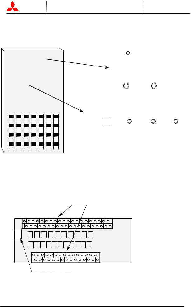
FIGURE 1.6 External I/F circuit PCB IOAU-04
4. External contact signal term inal
IOAU-04 |
5. RS232C D-sub connector |
MITSUBISHI ELECTRIC 9800A SERIES UPS

MITSUBISHI |
9800A SERIES UPS |
Page Number: |
ELECTRIC |
OWNERS / TECHNICAL MANUAL |
1-12 |
Description of Figures 1.4, 1.5, and 1.6:
1.CPM - Circuit protector for control power supply.
2.Switches on IFGR-G board : FOR SERVICE PERSONNEL ONLY (FIGURE 1.6):
-(4) External contact signal terminal
-(5) RS232C communication connector
3.Grounding bar (G)
4.External contact signal terminal block - Terminal block to connect contact signal input/output lines to and from the external devices. Refer to Figure 2.15 section 2.4 for details.
5.RS232C communication connector - Refer to Figure 2.18 section 2.5 for details.
6.Inverter start switch - This switch is used to transfer the UPS from static bypass to inverter during maintenance purposes. Transfers will lock-out if the bypass voltage is more than +12%,-12% of nominal.
*Uninterrupted switching is made at the time of synchronous operation. Switching is impossible at the time of asynchronous operation.
7.“INVERTER STOP” switch - This switch is used to transfer the UPS from inverter to static bypass during maintenance purposes. Do not operate it under normal operation. Transfers will lock-out if the bypass voltage is more than +12%,-12% of nominal.
*Uninterrupted switching is made at the time of synchronous operation. Switching is impossible at the time of asynchronous operation.
8.“FAULT RESET” switch (FOR SERVICE PERSONNEL ONLY) - This switch resets errors resulting from alarm conditions. (Do not operate this switch while inverter and converter are in operation.)
9.Maintenance (Set) button (FOR SERVICE PERSONNEL ONLY) - This switch sets the UPS menu parameters.
10.“Test mode” switch (FOR SERVICE PERSONNEL ONLY) - This switch changes system operation to the test-mode. (This switch should not be operated by personnel other than an Authorized Service Engineer).
11.“BOOT” switch (FOR SERVICE PERSONNEL ONLY) - This switch boots the processor in the main control circuit resulting from alarm conditions. (Do not operate this switch while inverter and converter are in operation).
MITSUBISHI ELECTRIC 9800A SERIES UPS

MITSUBISHI |
9800A SERIES UPS |
Page Number: |
ELECTRIC |
OWNERS / TECHNICAL MANUAL |
1-13 |
1.4Specifications
The UPS name plate displays the rated kVA as well as nominal voltages and currents. The name plate is located on the inside of the UPS front door.
|
TABLE 1.1 |
Power Specifications |
|
|
|
|
|
|
|
|||
|
|
|
|
|
|
|
|
|
|
|
|
|
|
Rated output |
Input voltage |
Bypass input voltage |
Output voltage |
|
|||||||
|
|
Power |
3 phase / 3 wire |
3 phase / 4 wire |
3 phase / 3 or 4 wire |
|
||||||
|
|
|
|
|
|
|
|
|
|
|
|
|
|
100kVA / |
80kW |
480V |
|
480V or 600V |
480V or 600V |
|
|||||
|
150kVA / 120kW |
480V |
|
480V or 600V |
480V or 600V |
|
||||||
|
225kVA / 180kW |
480V |
|
480V or 600V |
480V or 600V |
|
||||||
|
300kVA / 270kW |
480V |
|
480V or 600V |
480V or 600V |
|
||||||
|
375kVA / 338kW |
480V |
|
480V or 600V |
480V or 600V |
|
||||||
|
500kVA / 450kW |
480V |
|
480V or 600V |
480V or 600V |
|
||||||
|
750kVA / 675kW |
480V |
|
480V or 600V |
480V or 600V |
|
||||||
|
|
|
|
|
|
|
|
|
|
|
|
|
|
TABLE 1.2 UPS Module Information |
|
|
|
|
|
|
|
||||
|
|
|
|
|
|
|
|
|
|
|
||
|
UPS |
CABLE |
|
WIDTH |
DEPTH |
HEIGHT |
|
WEIGHT |
HEATING |
|
||
|
[kVA] |
ENTRY |
|
[in / mm] |
[in / mm] |
[in / mm] |
|
[lb./ kg] |
[kBTU/h] |
|
||
|
|
|
|
|
|
|
|
|
|
|
||
|
|
|
|
|
|
|
|
|
|
|||
|
100 |
BOTTOM |
|
43.3 / 1100 |
29.8 / 758 |
79.7 / 2025 |
|
2100 / 950 |
22.0 |
|
||
|
|
|
|
|
|
|
|
|
|
|
||
|
150 |
BOTTOM |
|
47.2 / 1200 |
29.8 / 758 |
79.7 / 2025 |
|
2820 / 1275 |
33.0 |
|
||
|
|
|
|
|
|
|
|
|
|
|
||
|
225 |
BOTTOM |
|
55.1 / 1400 |
29.8 / 758 |
79.7 / 2025 |
|
3310 / 1500 |
45.0 |
|
||
|
|
|
|
|
|
|
|
|
|
|
||
|
300 |
TOP |
|
76.8 / 1950 |
37.7 / 958 |
79.7 / 2025 |
|
4990 / 2260 |
68.0 |
|
||
|
|
|
|
|
|
|
|
|
|
|
||
|
375 |
TOP |
|
76.8 / 1950 |
37.7 / 958 |
79.7 / 2025 |
|
5250 / 2380 |
84.0 |
|
||
|
|
|
|
|
|
|
|
|
|
|
||
|
500 |
TOP |
|
114.2 / 2900 |
37.7 / 958 |
79.7 / 2025 |
|
6930 / 3140 |
98.0 |
|
||
|
|
|
|
|
|
|
|
|
|
|
||
|
750 |
TOP |
|
129.9 / 3300 |
49.5 / 1258 |
79.7 / 2025 |
|
9655 / 4380 |
136.1 |
|
||
|
|
|
|
|
|
|
|
|
|
|
|
|
MITSUBISHI ELECTRIC 9800A SERIES UPS

MITSUBISHI |
|
9800A SERIES UPS |
|
|
|
Page Number: |
|
||||||
ELECTRIC |
OWNERS / TECHNICAL MANUAL |
|
1-14 |
|
|
||||||||
TABLE 1.3 Detail of Specifications |
|
|
|
|
|
|
|
|
|
|
|
||
|
|
|
|
|
|
|
|
|
|
|
|
|
|
Rated Output kVA |
100 |
|
150 |
|
225 |
|
300 |
|
375 |
|
500 |
|
750 |
Rated Output kW |
80 |
|
120 |
|
180 |
|
270 |
|
338 |
|
450 |
|
675 |
|
|
|
AC |
INPUT |
|
|
|
|
|
|
|
|
|
Configuration |
3 phase, 3 wire |
|
|
|
|
|
|
|
|
|
|||
Voltage |
277/480 V, 346/600 V |
+15% to -15% |
|
|
|
|
|
||||||
Frequency |
60 Hz +/-5% |
|
|
|
|
|
|
|
|
|
|
|
|
Reflected Current THD |
6% max. at 100% load; |
9% max. at 50% load |
|
|
|
|
|||||||
|
|
STATIC BYPASS INPUT |
|
|
|
|
|
||||||
Configuration |
3 phase, 4 wire |
|
|
|
|
|
|
|
|
|
|||
Voltage |
277/480 V, 346/600 V |
+/-10% |
|
|
|
|
|
|
|||||
Frequency |
60 Hz |
|
|
|
|
|
|
|
|
|
|
|
|
|
|
|
BATTERY |
|
|
|
|
|
|
|
|||
Type |
Lead Acid |
|
|
|
|
|
|
|
|
|
|
|
|
Ride Through |
Application Specific |
|
|
|
|
|
|
|
|
|
|||
Nominal Voltage |
480 Vdc |
|
|
|
|
|
|
|
|
|
|
|
|
Minimum Voltage |
400 Vdc |
|
|
|
|
|
|
|
|
|
|
|
|
Number of Cells |
240 |
|
|
|
|
|
|
|
|
|
|
|
|
|
|
|
AC OUTPUT |
|
|
|
|
|
|
|
|||
Configuration |
3 phase, 4 wire |
|
|
|
|
|
|
|
|
|
|||
Voltage |
277/480 V, 346/600 V |
|
|
|
|
|
|
|
|
|
|||
Voltage Stability |
+/-1% |
|
|
|
|
|
|
|
|
|
|
|
|
Frequency |
60 Hz |
|
|
|
|
|
|
|
|
|
|
|
|
Frequency Stability |
+/-0.05% in free running mode |
|
|
|
|
|
|
|
|||||
Power Factor |
0.8 nominal |
|
|
|
|
0.9 nominal |
|
|
|
|
|
||
Power Factor range |
0.8 to 1.0 lagging (within output |
kW rating) |
|
|
|
|
|
||||||
Voltage THD |
2% maximum THD at 100% Linear Load |
|
|
|
|
|
|||||||
|
5% maximum THD at 100% non-linear load |
|
|
|
|
|
|||||||
Transient Response |
+/-2% maximum at 100% load step |
|
|
|
|
|
|||||||
|
+/-1% maximum at loss/return of AC power |
|
|
|
|
|
|||||||
|
+/-5% maximum at load transfer to/from static bypass |
|
|||||||||||
Transient Recovery |
Less than 20ms |
|
|
|
|
|
|
|
|
|
|||
Voltage Unbalance |
1% maximum at 100% unbalanced load |
|
|
|
|
|
|||||||
Phase Displacement |
1deg. maximum at 100% load |
|
|
|
|
|
|
|
|||||
Inverter Overload |
125% for 10 minutes; 150% for 1 minute |
|
|
|
|
|
|||||||
System Overload |
1000% for 1 cycle |
|
|
500% for 1 cycle |
|
|
|
|
|||||
|
(with bypass available) |
|
|
(with bypass available) |
|
||||||||
Bypass Overload |
125% for 10 minutes |
|
|
|
|
|
|
|
|
|
|||
Withstand Rating |
65kA* |
|
|
|
|
|
|
* : with optional fuse |
|
||||
|
|
|
ENVIRONMENTAL |
|
|
|
|
|
|||||
Cooling |
Forced Air |
|
|
|
|
|
|
|
|
|
|
|
|
Operating Temperature |
32 F to 104 F ( 0 C to 40 C). |
|
|
|
|
|
|
|
|||||
|
Recommended : 68 F to 86 F ( 20 C to 30 C) |
|
|
|
|
|
|||||||
Relative Humidity |
5% ~ 95% Non Condensing |
|
|
|
|
|
|
|
|||||
Altitude |
0 to 9000 feet No Derating |
|
|
|
|
|
|
|
|||||
Location |
Indoor (free from corrosive gases and dust) |
|
|
|
|
|
|||||||
Paint Color |
Munsell 5Y7/1 (Beige) |
|
|
|
|
|
|
|
|
|
|||
MITSUBISHI ELECTRIC 9800A SERIES UPS
MITSUBISHI |
9800A SERIES UPS |
Page Number: |
ELECTRIC |
OWNERS / TECHNICAL MANUAL |
1-15 |
TABLE 1.4 Rating of Contactors and Fuses
|
NUMBER |
APPLICATION |
|
|
|
|
|
OUTPUT CAPACITY OF EQUIPMENT |
|
|
|
|
|
||||||||
|
|
|
|
|
|
|
|
|
|
|
|
|
|
|
|
|
|
||||
|
|
|
100kVA |
150kVA |
225kVA |
300kVA |
375kVA |
500kVA |
750kVA |
||||||||||||
|
|
|
|
|
|
|
|
|
|
|
|
|
|
|
|
|
|
|
|
|
|
|
|
|
480V |
600V |
480V |
600V |
480V |
|
600V |
480V |
|
|
600V |
480V |
|
600V |
480V |
600V |
480V |
600V |
|
|
|
|
|
|
|
|
|
|
|
|
|
|
|
|
|
|
|
||||
|
CB1 |
AC input contactor |
135A |
200A |
350A |
450A |
660A |
660A |
910A |
||||||||||||
|
|
|
|
|
|
|
|
|
|
|
|
|
|
|
|
||||||
|
CB2 |
Battery disconnect |
400A |
600A |
800A |
1200A |
1600A |
(MEAU) |
(MEAU) |
||||||||||||
|
|
breaker |
|
|
|
|
|
|
|
|
|
|
|
|
|
|
|
|
|
|
|
|
CB3 |
STS contactor |
|
|
|
|
|
|
135A |
|
|
|
|
|
|
260A |
|||||
|
|
|
|
|
|
|
|
|
|
|
|
|
|
|
|
||||||
|
52C |
Inverter output |
135A |
200A |
350A |
450A |
450A |
660A |
910A |
||||||||||||
|
|
contactor |
|
|
|
|
|
|
|
|
|
|
|
|
|
|
|
|
|
|
|
|
52S |
Bypass contactor |
135A |
200A |
350A |
450A |
450A |
660A |
910A |
||||||||||||
|
|
|
|
|
|
|
|
|
|
|
|
|
|
|
|
|
|
|
|
||
|
88RC |
Control circuit contactor |
|
|
|
|
|
|
|
90A |
|
|
|
|
|
|
|
|
|||
|
|
|
|
|
|
|
|
|
|
|
|
|
|
|
|
|
|
|
|
||
F |
FCU, FCV, FCW |
AC input fuse |
200A/660V |
|
|
250A/660V |
|
|
|
|
|
|
|
315A/660V |
|
|
|||||
|
|
|
|
|
|
|
|
|
|
|
|
|
|
|
|
|
|
|
|
||
FIU, FIV, |
Inverter output fuse |
250A/660V |
200A/660V |
315A/660V |
315A/660V |
315A/660V |
315A/660V |
315A/660V |
|||||||||||||
U |
|||||||||||||||||||||
|
|
|
|
|
|
|
|
|
|
|
|
|
|
|
|
|
|
|
|
||
S |
|
|
|
|
|
|
|
|
|
|
|
|
|
|
|
|
|
|
|||
FUA, FUB, FUC |
Control power fuse |
|
|
|
|
|
|
|
30A/600V |
|
|
|
|
|
|
|
|||||
E |
|
|
|
|
|
|
|
|
|
|
|
|
|
|
|
|
|
|
|
|
|
(OPTION) |
Bypass input fuse |
200A/ |
- |
315A/ |
- |
250A/ |
|
- |
250A/ |
|
- |
315A/ |
|
- |
315A/ |
|
315A/ |
|
|||
S |
|
|
|
|
|
||||||||||||||||
FSU, FSV, FSW |
|
660V |
|
660V |
|
660V |
|
|
660V |
|
|
660V |
|
|
660V |
|
660V |
|
|||
|
FZS1, 2, 3 |
Bypass input ZNR fuse |
|
|
|
|
|
|
|
16A/500V |
|
|
|
|
|
|
|
||||
|
|
|
|
|
|
|
|
|
|
|
|
|
|
|
|
|
|
||||
|
FBS1, 2, 3 |
Control power fuse |
|
|
|
|
|
|
|
10A/600V |
|
|
|
|
|
|
|
||||
|
|
|
|
|
|
|
|
|
|
|
|
|
|
|
|
|
|
||||
|
FZR1, 2, 3 |
AC input ZNR fuse |
|
|
|
|
|
|
|
16A/500V |
|
|
|
|
|
|
|
||||
|
|
|
|
|
|
|
|
|
|
|
|
|
|
|
|
|
|
||||
|
FPU, FPV, FPW |
Parallel control |
|
|
|
|
|
|
|
10A/600V |
|
|
|
|
|
|
|
||||
|
|
circuit fuse |
|
|
|
|
|
|
|
|
|
|
|
|
|
|
|
|
|
|
|
|
|
|
|
|
|
|
|
|
|
|
|
|
|
|
|
|
|
|
|
|
|
*Rating would be changed.
MITSUBISHI ELECTRIC 9800A SERIES UPS
 Loading...