


 Loading...
INVERTER
FR-A700
PLC FUNCTION PROGRAMMING MANUAL
PLC FUNCTION Chapter 1
CC-Link Chapter 2
COMMUNICATION
SEQUENCE |
Chapter 3 |
PROGRAMMING |
|
|
|
|
|
ERROR CODE |
Chapter 4 |
LIST |
|

|
CONTENTS |
|
1. PLC FUNCTION |
1 |
|
1.1 |
Function Block Diagram ........................................................... |
2 |
1.2 |
PLC Function Specifications.................................................... |
3 |
1.3 |
System Configuration ............................................................... |
4 |
1.4Wiring of the Inverter and Personal Computer Using
GX Developer for RS-485 Communication |
..............................5 |
|
1.5 Prior to Sequence Program Creation ...................................... |
6 |
|
1.5.1 Precautions for sequence program creation ................................................. |
6 |
|
1.5.2 Usable main GX Developer functions ........................................................... |
6 |
|
1.5.3 Sequence program execution key................................................................. |
7 |
|
1.5.4 |
Sequence program write ............................................................................... |
8 |
1.5.5 Setting list of built-in PLC function parameter ............................................... |
9 |
|
1.6 Device Map............................................................................... |
10 |
|
1.6.1 |
I/O device map ............................................................................................ |
10 |
1.6.2 Internal relay (M) device map...................................................................... |
12 |
|
1.6.3 Data register (D) device map ...................................................................... |
12 |
|
1.6.4 |
Special relays.............................................................................................. |
12 |
1.6.5 |
Special registers.......................................................................................... |
14 |
1.7Inverter Status Monitoring, Special Registers for Control ..20
1.7.1 |
Data that can be read at all times................................................................ |
20 |
1.7.2 |
Data that are read by controlling (OFF to ON) the read command ............. |
23 |
1.7.3How to write data by controlling (OFF to ON) the write
|
|
command.................................................................................................... |
25 |
1.7.4 |
Inverter operation status control.................................................................. |
31 |
|
1.7.5 |
Inverter parameter access error (D9150) .................................................... |
33 |
|
1.7.6 |
Inverter status (D9151)................................................................................ |
33 |
|
1.8 |
Inverter Parameter Read/Write Method ................................. |
34 |
|
1.8.1 |
Reading the inverter parameters................................................................. |
34 |
|
1.8.2 |
Writing the inverter parameters................................................................... |
36 |
|
1.9 |
User Area Read/Write Method................................................ |
38 |
|
1.9.1 |
User parameter read/write method.............................................................. |
38 |
|
1.10 |
Analog I/O function ................................................................. |
39 |
|
1.10.1 |
Analog input ................................................................................................ |
39 |
|
1.10.2 |
Analog output .............................................................................................. |
39 |
|
1.11 |
Paluse train input function ..................................................... |
40 |
|
1.12 |
PID control ............................................................................... |
41 |
|
1.13 |
Inverter Operation Lock Mode Setting .................................. |
43 |
|
CONTENTS
I

2. CC-Link COMMUNICATION |
45 |
||
2.1 |
System Configuration............................................................. |
46 |
|
2.1.1 |
System configuration example.................................................................... |
46 |
|
2.1.2 |
Function block diagram............................................................................... |
47 |
|
2.2 |
CC-Link Parameters................................................................ |
49 |
|
2.2.1 CC-Link Extended Setting (Pr. 544)............................................................ |
49 |
||
2.3 |
CC-Link I/O Specifications ..................................................... |
50 |
|
2.4 |
Buffer Memory......................................................................... |
57 |
|
2.4.1 |
Remote output signals |
|
|
|
|
(Master module to inverter(FR-A7NC))....................................................... |
57 |
2.4.2 Remote input signals Pr.544=100 |
|
||
|
|
(Inverter(FR-A7NC) to master module)....................................................... |
58 |
2.4.3 |
Remote registers Pr.544=100 |
|
|
|
|
(Master module to inverter(FR-A7NC))....................................................... |
59 |
2.4.4 |
Remote registers Pr.544=100 |
|
|
|
|
(Inverter(FR-A7NC) to master module)...................................................... |
60 |
3. SEQUENCE PROGRAMMING |
61 |
||
3.1 |
Overview .................................................................................. |
62 |
|
3.1.1 Outline of Operation Processings ............................................................... |
62 |
||
3.2 |
RUN and STOP Operation Processings................................ |
64 |
|
3.3 |
Program Makeup..................................................................... |
64 |
|
3.4 |
Programming Languages....................................................... |
65 |
|
3.4.1 Relay symbolic language (Ladder mode) ................................................... |
65 |
||
3.4.2 Logic symbolic language (List mode).......................................................... |
67 |
||
3.5 |
Operation Processing Method of PLC Function .................. |
68 |
|
3.6 |
I/O Processing Method ........................................................... |
69 |
|
3.6.1 What is refresh system? ............................................................................. |
69 |
||
3.6.2 Response delay in refresh system.............................................................. |
70 |
||
3.7 |
Scan Time ................................................................................ |
71 |
|
3.8 |
Numerical Values Usable in Sequence Program ................. |
72 |
|
3.8.1 |
BIN (Binary Code)....................................................................................... |
73 |
|
3.8.2 |
HEX (HEX Decimal).................................................................................... |
74 |
|
3.9 |
Description of devices............................................................ |
75 |
|
3.9.1 |
Device List .................................................................................................. |
75 |
|
3.9.2 Inputs, Outputs X, Y.................................................................................... |
76 |
||
3.9.3 |
Internal Relays M ........................................................................................ |
79 |
|
3.9.4 |
Timers T...................................................................................................... |
80 |
|
II

3.9.5 |
100ms, 10ms and 100ms retentive timers .................................................. |
80 |
|
3.9.6 |
Timer processing method and accuracy ..................................................... |
81 |
|
3.10 |
Counters C ............................................................................... |
83 |
|
3.10.1 |
Count processing in refresh system ............................................................ |
84 |
|
3.10.2 |
Maximum counting speed of counter .......................................................... |
85 |
|
3.11 |
Data Registers D...................................................................... |
86 |
|
3.12 |
Special Relays, Special Registers ......................................... |
87 |
|
3.13 |
Function List............................................................................ |
89 |
|
3.14 |
How to RUN/STOP the Built-in PLC Function from Outside (Re- |
||
|
mote RUN/STOP) ..................................................................... |
90 |
|
3.15 |
Watchdog Timer (Operation clog up monitor timer)............ |
92 |
|
3.16 |
Self-diagnostic Function ........................................................ |
93 |
|
3.16.1 |
Error-time operation mode .......................................................................... |
94 |
|
3.17 |
Keyword Registration ............................................................. |
95 |
|
3.18 |
Setting of Output (Y) Status at Switching from STOP Status to |
||
|
RUN Status............................................................................... |
96 |
|
3.19 |
Instruction Format................................................................... |
97 |
|
3.20 |
Bit Device Processing Method............................................... |
99 |
|
3.20.1 |
1-bit processing ........................................................................................... |
99 |
|
3.20.2 |
Digit designation processing ....................................................................... |
99 |
|
3.21 |
Handling of Numerical Value................................................ |
101 |
|
3.22 |
Operation Error...................................................................... |
102 |
|
3.23 |
Instructions List .................................................................... |
103 |
|
3.23.1 |
How to use the instruction list.................................................................... |
103 |
|
3.23.2 |
Sequence instruction................................................................................. |
105 |
|
3.23.3 |
Basic instructions ...................................................................................... |
107 |
|
3.23.4 |
Application instructions.............................................................................. |
109 |
|
3.24 |
Description of the Instructions ............................................ |
110 |
|
3.25 |
Sequence Instructions.......................................................... |
111 |
|
3.25.1 |
Contact Instructions : |
|
|
|
|
Operation start, series connection, parallel connection ... LD, LDI, AND, ANI, |
|
|
|
OR, ORI..................................................................................................... |
111 |
3.25.2 |
Contact Instructions : Ladder block series connection, parallel connection ... |
||
|
|
ANB, ORB ................................................................................................. |
113 |
3.25.3 |
Connection Instructions : |
|
|
|
|
Ladder block series connection, parallel connection ... ANB, ORB........... |
117 |
3.25.4 |
Connection Instructions : |
|
|
|
|
Operation result, push, read, pop ... MPS, MRD, MPP ............................. |
120 |
3.25.5 |
Output Instructions : Bit device, timer, counter ... OUT ............................. |
123 |
|
CONTENTS
III

3.25.6 |
Output Instructions : Device set, reset ... |
SET, RST................................. |
126 |
|||||
3.25.7 Output Instructions : Leading edge, trailing edge differential outputs ... |
PLS, |
|||||||
|
|
PLF ........................................................................................................... |
|
|
|
|
|
129 |
3.25.8 |
Shift Instructions : Bit device shift ... |
SFT, SFTP ...................................... |
131 |
|||||
3.25.9 |
Master Control Instructions : Master control set, reset ... MC, MCR......... |
133 |
||||||
3.25.10End Instruction : Sequence program end |
... END..................................... |
137 |
||||||
3.25.11Other Instructions : No operation ... |
NOP |
................................................. |
138 |
|||||
3.26 |
Basic Instructions |
................................................................. |
|
|
|
|
140 |
|
3.26.1 |
Comparison Operation Instructions .......................................................... |
|
140 |
|||||
3.26.2 Comparison Operation Instructions : |
|
|
||||||
|
|
16-bit data comparison ... |
=, <>, >, <=, <, >=............................................ |
142 |
||||
3.26.3 |
Arithmetic Operation Instructions.............................................................. |
|
|
144 |
||||
3.26.4 Arithmetic Operation Instructions : |
|
|
|
|||||
|
|
BIN 16-bit addition, subtraction ... |
+, +P, -, -P .......................................... |
145 |
||||
3.26.5 Arithmetic Operation Instructions : |
|
|
|
|||||
|
|
BIN 16-bit multiplication, division ... |
*, *P, /, /P.......................................... |
149 |
||||
3.26.6 |
Data Transfer Instructions......................................................................... |
|
|
|
153 |
|||
3.26.7 Data Transfer Instructions : |
|
|
|
|
||||
|
|
16-bit data transfer ... |
MOV, MOVP .......................................................... |
|
153 |
|||
3.27 |
Application instructions....................................................... |
|
|
|
155 |
|||
3.27.1 |
Logical Operation Instructions .................................................................. |
|
|
155 |
||||
3.27.2 Logical Operation Instructions : |
|
|
|
|||||
|
|
16-bit Logical Product ... |
WAND, WANDP................................................ |
156 |
||||
3.27.3 Logical Operation Instructions : |
|
|
|
|||||
|
|
16-bit Logical Add ... |
WOR, WORP .......................................................... |
|
159 |
|||
3.27.4 Logical Operation Instructions : |
|
|
|
|||||
|
|
16-bit Exclusive Logical Add ... |
WXOR, WXORP ..................................... |
162 |
||||
3.27.5 Logical Operation Instructions : |
|
|
|
|||||
|
|
16-bit NOT Exclusive Logical Add |
... WXNR, WXNRP ............................. |
165 |
||||
3.27.6 Logical Operation Instructions : |
|
|
|
|||||
|
|
BIN 16-bit 2’s complement ... |
NEG, NEGP............................................... |
168 |
||||
4. ERROR CODE LIST |
171 |
4.1 How to Read the Error Code ................................................ |
172 |
APPENDIX |
175 |
Appendix1Instruction Processing Time ....................................... |
176 |
IV

1. PLC FUNCTION
This manual describes the functions and devices necessary for programming.
1.1 |
Function Block Diagram ...................................... |
2 |
1.2 |
PLC Function Specifications............................... |
3 |
1.3 |
System Configuration .......................................... |
4 |
1.4Wiring of the Inverter and Personal Computer
|
Using GX Developer for RS-485 Communication... |
5 |
1.5 |
Prior to Sequence Program Creation ................. |
6 |
1.6 |
Device Map............................................................ |
10 |
1.7Inverter Status Monitoring, Special Registers
|
for Control............................................................. |
20 |
1.8 |
Inverter Parameter Read/Write Method .............. |
34 |
1.9 |
User Area Read/Write Method ............................. |
38 |
1.10 |
Analog I/O function .............................................. |
39 |
1.11 |
Paluse train input function .................................. |
40 |
1.12 |
PID control ............................................................ |
41 |
1.13 |
Inverter Operation Lock Mode Setting ............... |
43 |
Chapter 1
Chapter 2
Chapter 3
Chapter 4
1
Function Block Diagram
1.1 Function Block Diagram
How I/O data are transferred to/from the inverter by the built-in PLC function is explained using function blocks.
(1)I/O data read, write, etc. can be performed by accessing the inverter in the predetermined method using special relays, special registers, etc.
(2)Operation, parameter read/write, etc. can be performed in accordance with the created sequence programs (built in the inverter) using input data from the control input terminals.
With the output signals, output data can be output to outside the inverter from the control output terminals as not only the inverter's status signals but also pilot lamp on/off, interlock and other control signals set freely by the user.
Inverter
Input signal 
Output signal
Built-in sequence program
I/O data
Special relays, special registers, etc.
Inverter CPU
2

PLC Function Specifications
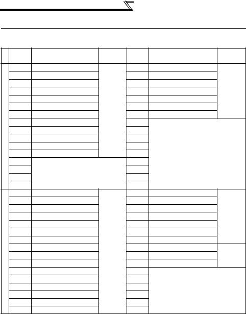
1.2 PLC Function Specifications
The following table indicates the program capacity and devices of the PLC function.
|
|
|
|
A700 Sequence Section |
|
Control method |
|
Repeated operation (by stored program) |
|||
I/O control method |
|
Refresh |
|||
Programming language |
Relay symbolic language (ladder mode) |
||||
Logic symbolic language (list mode) |
|||||
|
|
|
|
||
Number of instruction |
PLC instructions |
23 |
|||
Basic instructions |
32 |
||||
Application instructions |
18 |
||||
|
|
|
|
||
|
|
|
|
|
|
Processing speed |
|
PLC instruction 1.9 s to 12 s/step(*2) |
|||
|
|
|
|
128 (X: 64 points, Y: 64 points) |
|
Number of I/O points |
|
19 points installed, X: 12 points, Y: 7 points (*1) |
|||
|
FR-A7AX, X: 16 points |
||||
|
|
|
|
FR-A7AY, Y: 6 points |
|
|
|
|
|
FR-A7AR, Y: 3 points |
|
Number of analog I/O points |
5 points installed, Input: 3 points, Output: 2 points |
||||
FR-A7AY output: 2 points |
|||||
|
|
|
|
||
Watchdog timer |
|
10 to 2000(ms) |
|||
Memory capacity |
|
6k bytes used by sequence and parameters. |
|||
Program capacity |
|
1k step |
|||
|
Internal relay (M) |
64(M0 to M63) |
|||
|
Latch relay (L) |
|
None (Can be set with parameters but will not latch) |
||
|
Step relay (S) |
|
None (Can be set with parameters but will operate as M) |
||
|
Link relay (B) |
|
None |
||
|
|
|
Points |
16 |
|
|
Timer (T) |
|
100ms timer: Set time 0.1 to 3276.7s (T0 to T15) |
||
|
Specifications |
10ms timer: Set time 0.01 to 327.67s |
|||
|
|
|
|||
|
|
|
|
100ms retentive timer: Set time 0.1 to 3276.7s |
|
Devices |
Counter (C) |
|
Points |
16 |
|
|
Specifications |
Normal counter: Setting range 1 to 32767 (C0 to C15) |
|||
|
|
Interrupt program counter: None |
|||
|
|
|
|||
Data device (D) |
|
120(D0 to D119) |
|||
|
Link register (W) |
None |
|||
|
Annunciator (F) |
|
None |
||
|
File register (R) |
|
None |
||
|
Accumulator (A) |
None |
|||
|
Index register (Z, V) |
None |
|||
|
Pointer (P) |
|
None |
||
|
Interrupt pointer (I) |
None |
|||
|
Special relay (M) |
256 (M9000 to 9255) with function limit |
|||
|
Special register (D) |
256 (D9000 to 9255) with function limit |
|||
*1 These signals use the same terminals as used by the input and output signals given in the common specifications of the inverter.
One point is always necessary for a sequence start (RUN/STOP).
*2 As inverter control is also performed actually, the scan time is approximately 40ms at 500 steps.
1
PLC FUNCTION
3
System Configuration
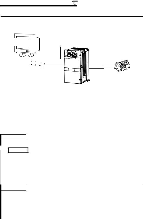
1.3 System Configuration
The following shows the system configuration for use of the PLC function.
<System configuration example>
GX Developer: |
|
FR-A700 |
Programming tool |
|
|
|
|
|
|
|
PU connector |
|
RS-232C/ |
|
|
RS-485 |
|
|
converter |
Motor |
|
|
3-phase AC 


 power supply


Communication specifications
Set the following setting in communication parameters of the inverter.
Inverter Parameter |
GX Developer Setting |
|
Inverter initial setting |
Pr.118 PU communication speed |
96 (9600bps) |
192 (19200bps) |
|
Pr.119 PU communication stop bit length |
0 (data length: 8 bits, stop |
1 |
(data length: 8 bits, stop |
|
bit: 1 bit) |
bit: 2 bit) |
|
Pr.120 PU communication parity check |
1 (with odd parity check) |
2 |
(with even parity check) |
Pr.122 PU communication check time |
9999 (without |
9999 (without |
|
interval |
communication check) |
communication check) |
|
REMARKS
•For futher details, refer to the Inverter instruction manual (applied).
POINT
•Support GX Developer ver.8.0 or more
•GX Developer Setting
PLC series |
ACPU |
|
|
|
PLC type |
A0J2H |
|
|
|
|
|
|||
[Project data list]→[Parameter]→[PLC parameter]→[A parameter] |
1k step |
|||
→«Memory capacity» tab→"Program capacity"→"Sequence"→"main" |
||||
|
||||
REMARKS
•Refer to the Inverter instruction manual (applied) for wiring.
•Refer to the GX Developer manuals for the specifications related to GX Developer and the personal computer that uses GX Developer.
GX Developer Version xx Operating manual
GX Developer Version xx Operating manual (startup)
•The programming tool that can be used is GX Developer only. (The A6GPP, A7PHP, etc. cannot be used.)
4
Wiring of the Inverter and Personal Computer Using
GX Developer for RS-485 Communication
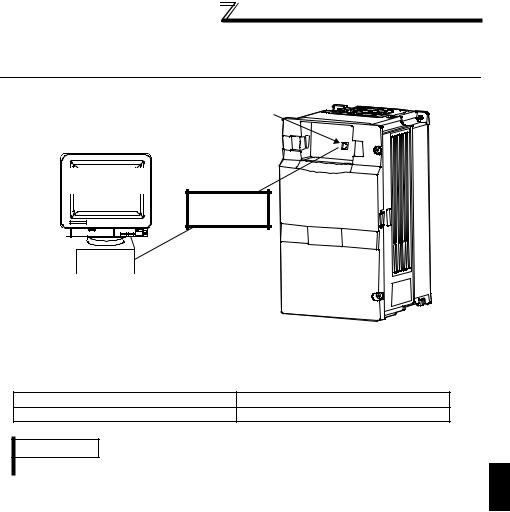
1.4Wiring of the Inverter and Personal Computer Using GX Developer for RS-485 Communication
PU connector
Personal computer
GX Developer :
Programming tool
RS-232C-RS-485 converter
RS-232C connector
zPersonal computer - inverter connection cable
Make connection after conversion between RS-232C and RS-485.
Examples of commercially available products (as of Sep., '05)
Type |
Maker |
SC-FRPC |
BEIJERS |
REMARKS
When fabricating the cable on the user side, refer to the inverter instruction manual (applied).
1
PLC FUNCTION
5
Prior to Sequence Program Creation
1.5 Prior to Sequence Program Creation
1.5.1Precautions for sequence program creation
POINT
•Online change of the sequence program and access to other stations are not allowed.
In addition, program read/write from other stations and all PLC memory clear cannot be performed.
•Back up the ladder configured with the protective function of GX Developer.
If any of the instructions (refer to page 103) and devices (refer to page 3) that cannot be used with the built-in PLC function exists in a sequence program, an instruction code error occurs at the execution of that instruction.
Error code |
D9008=10 |
Operation error step |
D9010 |
|
D9011 |
REMARKS
•Refer to page 22 for the error codes.
1.5.2Usable main GX Developer functions
zParameter or sequence program read/write
zLadder monitor
zDevice monitor
zDevice test
zAll device memory clear
zRemote RUN/STOP
CAUTION
Device test ([Online] - [Debug] - [Device test]) of GX Developer can be performed, but if devices corresponding to control terminal (e.g. STF, STR) signals are tested, the devices turn on in the sequence but the inverter does not perform the corresponding operation.
6
Prior to Sequence Program Creation
1.5.3Sequence program execution key
The sequence program execution key (STOP/RUN) of the PLC is switched by turning off/on the SQ signal.
POINT
•For the terminal used for SQ signal input, set "50" in any of Pr.178 to Pr. 189 to assign the function.
•SQ-SD must be shorted to execute the built-in PLC function.
CAUTION
If the SQ signal is not turned on, the start signal of the inverter is designed to become valid by the factory setting of Pr.415 Inverter operation lock mode setting.
Open (STOP) the SQ signal-SD terminals when writing a sequence program, for example.
When executing the sequence program, short (RUN) the SQ signal-SD terminals. Remote run/stop of the built-in PLC function can be executed in any of the following methods:
• Setting using the built-in PLC function parameter (contact)
• Using GX Developer
• Via CC-Link communication (refer to page 49)
REMARKS
•The validity limit of the SQ signal can be controlled using Pr.415 Inverter operation lock mode setting. (Refer to page 43.)
CAUTION
The outputs (Y) are cleared by turning the SQ signal off (STOP) after sequence program |
|
execution (SQ signal on). |
|
The other devices retain the device data prior to STOP. When you want to clear the |
|
remaining device data, power off or reset (short RES-SD for 0.1s, then open) the |
|
inverter. |
1 |
|
PLC FUNCTION
7
Prior to Sequence Program Creation
1.5.4Sequence program write
POINT
Sequence program write can be performed in any operation mode.
When rewriting the PLC function parameters and sequence program using GX Developer, check the following:
1)Check that the sequence program execution key is in the STOP position (SQ signal is off) (refer to page 7).
2)Check that the inverter is at a stop.
3)Check that the communication specification setting parameters (Pr.117 to Pr.124) are set correctly. If any of these parameters is set incorrectly, communication with GX Developer cannot be made.
REMARKS
Check and set the communication specification parameter (Pr. 117 to Pr. 124) using the parameter unit (FR-PU04/FR-PU07). (Refer to the FR-PU04/FR-PU07 instruction manual for the handling of the FR-PU04/FR-PU07.) GX Developer and the FR-PU04/FR-PU07 cannot be connected and used simultaneously.
4)Check the PLC series and sequence program capacity in the GX Developer parameters (refer to page 4).
5)Refer to the GX Developer manual and write the sequence program.
CAUTION
•A sequence program cannot be written with its steps specified. If written, the sequence program does not run. (The program outside the specified range is initialized.)
•Do not read the built-in PLC function parameters and sequence program without writing them to the inverter once using GX Developer. Since the inverter does not have normal data, always write the built-in PLC function parameters and sequence program once.
•Since the built-in PLC function parameters and sequence program are written to the flash ROM, there are restrictions on the number of write times. (Approximately 100,000 times)
8

Function Block Diagram
1.5.5Setting list of built-in PLC function parameter
The built-in PLC function parameters are designed to specify the ranges of using the PLC function, e.g. program capacity, device assignment and various functions.
Item |
GX Developer Default |
Setting Range |
|
<Usable device range> |
|||
|
|
||
Sequence program |
6k steps |
1k step |
|
capacity |
|||
|
|
||
File register capacity |
None |
Cannot be set (default) |
|
Comment capacity |
None |
Cannot be set (default) |
|
Status latch |
None |
Cannot be set (default) |
|
Sampling trace |
None |
Cannot be set (default) |
|
Microcomputer program |
None |
Cannot be set (default) |
|
capacity |
|||
|
|
||
Latch range setting |
L1000 to L2047 |
Cannot be set (invalid if set) |
|
Link range setting |
None |
Cannot be set (default) |
|
I/O assignment |
None |
Cannot be set (default) |
|
Internal relay, latch relay, |
M0 to 999 |
L and S cannot be set. |
|
L1000 to 2047 |
(Operates as M if set) |
||
step relay setting |
|||
None for S |
<M0 to M63> |
||
|
|||
Watchdog timer setting |
200ms |
10 to 2000ms |
|
|
100ms: T0 to 199 |
16 points for 100ms, 10ms and |
|
Timer setting |
10ms: T200 to 255 |
retentive timers. Timers have |
|
(100ms timers since only T0 to 7 |
consecutive numbers. |
||
|
|||
|
are available) |
<T0 to T15> |
|
Counter setting |
Without interrupt counters |
Cannot be set (default) |
|
<C0 to C15> |
|||
|
|
||
|
|
Can be set using X0 to 1F. |
|
Remote run/pause |
None |
Otherwise invalid. Pause does not |
|
|
|
function. |
|
|
Fuse blow: Continued |
Setting invalid (since there are no |
|
|
fuses) |
||
|
|
||
|
I/O verify error: Stop |
Setting invalid |
|
Error-time operation mode |
(since there are no I/O modules) |
||
|
|||
|
Operation error: Continued |
Stop/Continued |
|
|
Special function module check |
Setting invalid (since there are no |
|
|
error: Stop |
special modules) |
|
STOP → RUN output mode |
Operation status prior to |
Prior to STOP/after operation |
|
STOP is re-output. |
execution |
||
|
|||
Print title registration |
None |
Cannot be set |
|
Keyword registration |
None |
Online setting cannot be made but |
|
parameter setting is valid. |
|||
|
|
REMARKS
•The following functions are not supported.
1. Constant scan, 2. Latch (device data backup for power failure), 3. Pause,
4. Status latch, 5. Sampling trace, 6. Offline switch
•If parameter clear of the inverter is performed, the above built-in PLC function parameters are not cleared.
•For the built-in PLC function parameter setting operation, refer to the GX Developer Operating Manual.
1
PLC FUNCTION
9
Device Map
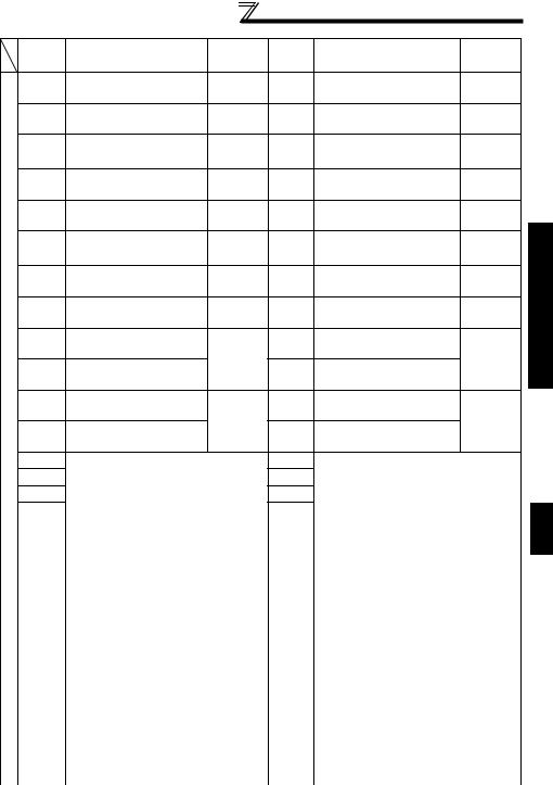
1.6 Device Map
1.6.1I/O device map
|
Device |
Name |
Remarks |
Device |
Name |
Remarks |
|
|
No. |
|
|
No. |
|
|
|
|
X00 |
STF terminal |
|
Y00 |
RUN terminal |
|
|
|
X01 |
STR terminal |
|
Y01 |
SU terminal |
|
|
|
X02 |
RH terminal |
|
Y02 |
OL terminal |
External |
|
|
X03 |
RM terminal |
|
Y03 |
IPF terminal |
||
|
|
terminal |
|||||
|
X04 |
RL terminal |
|
Y04 |
FU terminal |
||
|
|
|
|||||
I/O |
X05 |
JOG terminal |
External |
Y05 |
ABC1 terminal |
|
|
X06 |
RT terminal |
terminal |
Y06 |
ABC2 terminal |
|
||
X07 |
AU terminal |
|
Y07 |
|
|
||
External |
|
|
|
||||
X08 |
CS terminal |
|
Y08 |
|
|
||
X09 |
MRS terminal |
|
Y09 |
|
|
||
|
X0A |
STOP terminal |
|
Y0A |
|
|
|
|
X0B |
RES terminal |
|
Y0B |
Empty |
|
|
|
X0C |
|
|
Y0C |
|
|
|
|
X0D |
Empty |
|
Y0D |
|
|
|
|
X0E |
|
|
Y0E |
|
|
|
|
X0F |
|
|
Y0F |
|
|
|
|
X10 |
X0 terminal |
|
Y10 |
DO0 terminal |
|
|
|
X11 |
X1 terminal |
|
Y11 |
DO1 terminal |
|
|
|
X12 |
X2 terminal |
|
Y12 |
DO2 terminal |
Dgital |
|
|
X13 |
X3 terminal |
|
Y13 |
DO3 terminal |
output |
|
|
X14 |
X4 terminal |
|
Y14 |
DO4 terminal |
FR-A7AY |
|
I/O |
X15 |
X5 terminal |
|
Y15 |
DO5 terminal |
|
|
X16 |
X6 terminal |
16bit |
Y16 |
DO6 terminal |
|
||
option |
|
||||||
X17 |
X7 terminal |
digital |
Y17 |
RA1 terminal |
Relay |
||
X18 |
X8 terminal |
Input |
Y18 |
RA2 terminal |
output |
||
in |
|||||||
X19 |
X9 terminal |
FR-A7AX |
Y19 |
RA3 terminal |
FR-A7AR |
||
Plug |
|||||||
X1A |
X10 terminal |
|
Y1A |
|
|
||
|
X1B |
X11 terminal |
|
Y1B |
|
|
|
|
X1C |
X12 terminal |
|
Y1C |
Empty |
|
|
|
X1D |
X13 terminal |
|
Y1D |
|
|
|
|
X1E |
X14 terminal |
|
Y1E |
|
|
|
|
X1F |
X15 terminal |
|
Y1F |
|
|
|
10 |
|
|
|
|
|
|
|
|
|
|
|
|
Device Map |
|
|
Device |
Name |
Remarks |
Device |
Name |
Remarks |
|
|
No. |
|
|
No. |
|
|
|
|
X20 |
Operation mode setting |
D9140 |
Y20 |
Operation mode setting |
D9140 |
|
|
|
read completion |
|
|
read command |
|
|
|
X21 |
Set frequency read |
D9141 |
Y21 |
Set frequency read |
D9141 |
|
|
|
completion (RAM) |
|
|
command (RAM) |
|
|
|
X22 |
Set frequency read |
D9142 |
Y22 |
Set frequency read |
D9142 |
|
|
completion (E2PROM) |
command (E2PROM) |
|
||||
|
X23 |
Operation mode setting |
D9143 |
Y23 |
Operation mode setting |
D9143 |
|
|
write completion |
write command |
|
||||
|
X24 |
Set frequency write |
D9144 |
Y24 |
Set frequency write |
D9144 |
|
|
completion (RAM) |
command (RAM) |
|
||||
|
X25 |
Set frequency write |
D9145 |
Y25 |
Set frequency write |
D9145 |
|
SystemI/O |
completion (E2PROM) |
command (E2PROM) |
|
||||
X26 |
Alarm definition batch |
D9146 |
Y26 |
Alarm definition batch |
D9146 |
DeviceMap |
|
clear completion |
clear command |
||||||
|
Parameter read |
|
|
Parameter read request |
|
||
|
X27 |
Parameter clear |
D9147 |
Y27 |
Parameter clear commandD9147 |
|
|
|
completion |
|
|||||
|
|
|
|
|
|
|
|
|
X28 |
completion (RAM) |
D9241, |
Y28 |
(RAM) |
D9241, |
|
|
|
Parameter write |
D9242, |
|
Parameter write request |
D9242, |
|
|
X29 |
D9234 |
Y29 |
D9234 |
|
||
|
|
completion (RAM) |
|
|
(RAM) |
|
|
|
X2A |
Parameter read |
D9243, |
Y2A |
Parameter read request |
D9243, |
|
|
completion (EEPROM) |
(EEPROM) |
|
||||
|
|
Parameter write |
D9244, |
|
Parameter write request |
D9244, |
|
|
X2B |
D9235 |
Y2B |
D9235 |
|
||
|
|
completion (EEPROM) |
|
|
(EEPROM) |
|
|
|
X2C |
|
|
Y2C |
|
|
|
|
X2D |
System area |
|
Y2D |
System area |
|
|
|
X2E |
|
Y2E |
|
|
||
|
X2F |
|
|
Y2F |
|
|
|
|
|
|
|
|
|
|
1 |
|
|
X30 |
RY0 |
|
Y30 |
RX0 |
|
||
|
X31 |
RY1 |
|
Y31 |
RX1 |
|
|
|
|
X32 |
RY2 |
|
Y32 |
RX2 |
|
FUNCTIONPLC |
|
I/Oremote |
X37 |
RY7 |
|
Y37 |
RX7 |
|
||
|
X33 |
RY3 |
|
Y33 |
RX3 |
|
|
|
|
X34 |
RY4 |
|
Y34 |
RX4 |
|
|
|
|
X35 |
RY5 |
|
Y35 |
RX5 |
|
|
|
|
X36 |
RY6 |
|
Y36 |
RX6 |
|
|
|
I/O |
|
|
FR-A7NC |
|
|
FR-A7NC |
||
X38 |
RY8 |
Y38 |
RX8 |
|||||
|
|
|
||||||
-Link |
X39 |
RY9 |
|
Y39 |
RX9 |
|
|
|
X3A |
RYA |
|
Y3A |
RXA |
|
|
||
CC |
|
|
|
|
|
|
|
|
X3B |
RYB |
|
Y3B |
RXB |
|
|
||
|
X3C |
RYC |
|
Y3C |
RXC |
|
|
|
|
X3D |
RYD |
|
Y3D |
RXD |
|
|
|
|
X3E |
RYE |
|
Y3E |
RXE |
|
|
|
|
X3F |
RYF |
|
Y3F |
RXF |
|
|
|
|
|
|
|
|
|
11 |
||

Device Map
1.6.2Internal relay (M) device map
Device No. |
Description |
M0 to M63 Use freely on user side.
1.6.3 Data register (D) device map
Data |
Inverter Pr. |
|
Parameter Name |
Reference |
|
Register (D) |
Number |
|
Page |
||
|
|
||||
D0 to D99 |
Use freely on |
user side. |
|
— |
|
D100 to D119 |
Pr.506 to |
User parameters. Use freely on user side. |
38 |
||
Pr.515 |
|||||
|
|
|
|
||
1.6.4 Special relays |
|
|
|||
The special relays are internal relays with special applications and therefore should not be switched on-off in the program.
Number |
Name |
Description |
|
M9008 |
Self-diagnostic error |
Turned on by self-diagnosed error. |
|
M9010 |
Operation error flag |
Turned on by an instruction execution error. |
|
Turned off when error is removed. |
|||
|
|
||
M9011 |
Operation error flag |
Turned on by an instruction execution error. |
|
Remains on after normal status is restored. |
|||
|
|
||
M9036 |
Normally ON |
M9036 and M9037 are turned on and off independently |
|
M9037 |
Normally OFF |
||
of STOP or RUN. |
|||
|
On only for 1 scan after |
||
M9038 |
M9038 and M9039 change depending on the STOP or |
||
|
RUN |
RUN status. In other than the STOP status, M9038 is on |
|
|
Off only for 1 scan after |
||
M9039 |
for one scan only and M9039 is off for one scan only. |
||
|
RUN |
|
|
M9200 |
Inverter operation status |
Control the STF terminal of the inverter from PLC |
|
control flag (STF) |
function |
||
|
|||
M9201 |
Inverter operation status |
Control the STR terminal of the inverter from PLC |
|
control flag (STR) |
function |
||
|
|||
M9202 |
Inverter operation status |
Control the RH terminal of the inverter from PLC |
|
control flag (RH) |
function |
||
|
|||
M9203 |
Inverter operation status |
Control the RM terminal of the inverter from PLC |
|
control flag (RM) |
function |
||
|
|||
M9204 |
Inverter operation status |
Control the RL terminal of the inverter from PLC function |
|
|
control flag (RL) |
|
|
M9205 |
Inverter operation status |
Control the JOG terminal of the inverter from PLC |
|
control flag (JOG) |
function |
||
|
|||
M9206 |
Inverter operation status |
Control the RT terminal of the inverter from PLC function |
|
|
control flag (RT) |
|
|
M9207 |
Inverter operation status |
Control the AU terminal of the inverter from PLC |
|
control flag (AU) |
function |
||
|
|||
M9208 |
Inverter operation status |
Control the CS terminal of the inverter from PLC |
|
control flag (CS) |
function |
||
|
|||
M9209 |
Inverter operation status |
Control the MRS terminal of the inverter from PLC |
|
control flag (MRS) |
function |
||
|
|||
M9210 |
Inverter operation status |
Control the STOP terminal of the inverter from PLC |
|
control flag (STOP) |
function |
||
|
|||
12 |
|
|

Device Map
Number |
Name |
Description |
|
M9211 |
Inverter operation status |
Control the RES terminal of the inverter from PLC |
|
control flag (RES) |
function |
||
|
|||
M9216 |
Inverter status (RUN) |
Inverter running |
|
M9217 |
Inverter status (FWD) |
Forward running |
|
M9218 |
Inverter status (REV) |
Reverse running |
|
M9219 |
Inverter status (SU) |
Up to frequency |
|
M9220 |
Inverter status (OL) |
Overload alarm |
|
M9221 |
Inverter status (IPF) |
Instantaneous power failure/undervoltage |
|
M9222 |
Inverter status (FU) |
Output frequency detection |
|
M9223 |
Inverter status (ALM) |
Alarm output |
|
M9224 |
Inverter status (LF) |
Minor fault output |
|
M9225 |
Inverter status (DO0) |
Status of output terminal function set in Pr. 313 is stored *1 |
|
M9226 |
Inverter status (DO1) |
Status of output terminal function set in Pr. 314 is stored *1 |
|
M9227 |
Inverter status (DO2) |
Status of output terminal function set in Pr. 315 is stored *1 |
|
M9228 |
Inverter status (DO3) |
Status of output terminal function set in Pr. 316 is stored *1 |
|
M9229 |
Inverter status (DO4) |
Status of output terminal function set in Pr. 317 is stored *1 |
|
M9230 |
Inverter status (DO5) |
Status of output terminal function set in Pr. 318 is stored *1 |
|
M9231 |
Inverter status (DO6) |
Status of output terminal function set in Pr. 319 is stored *1 |
|
M9232 |
Inverter status (RA1) |
Status of output terminal function set in Pr. 320 is stored *1 |
|
M9233 |
Inverter status (RA2) |
Status of output terminal function set in Pr. 321 is stored *1 |
|
M9234 |
Inverter status (RA3) |
Status of output terminal function set in Pr. 322 is stored *1 |
|
|
|
Select the inverter status control command from M9200 |
|
M9255 |
Inverter operation status |
to M9211 or D9148. |
|
control selection |
OFF: Special relay selection |
||
|
|||
|
|
ON : Special register selection |
|
*1. Even if the FR-A7AY, FR-A7AR is not mounted, Pr. 313 to Pr. 322 are accessible during |
|||
PLC function operation, and status of output terminal functions are stored in each device. |
|||
(virtual output terminal) |
|
||
Device Map
1
PLC FUNCTION
13
Device Map
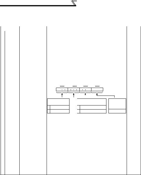
1.6.5Special registers
The special registers are data registers with special applications and therefore data should not be written to the special registers in the program.
Number |
Name |
Description |
Page |
|
|
D9008 |
Self-diagnostic |
Stores the self-diagnosed error number in BIN. (Refer |
22 |
|
error |
to page 22 for the error codes.) |
||
|
|
|
||
|
|
Operation error |
Stores the step number in BIN, at which an instruction |
|
|
D9010 |
execution error occurred. After that, data is updated |
— |
|
|
step |
|||
|
|
each time operation error occurs. |
|
|
|
|
|
|
|
|
|
|
Stores the step number in BIN, at which an instruction |
|
|
D9011 |
Operation error |
error occurred. Since data is stored into D9011 when |
— |
|
step |
M9011 turns from off to on, D9011 data is not updated |
||
|
|
|
||
|
|
|
unless M9011 is cleared by the user program. |
|
|
D9014 |
I/O control |
3 (fixed): Both input and output refreshes |
— |
|
method |
|||
|
|
|
|
|
|
|
|
Stores the operating status of the PLC function. |
|
registers |
|
|
|
|
B15 |
B12B11 |
B8B7 |
B4B3 |
B0 |
|
|
|
|
|||
D9015 |
CPU operating |
|
|
|
|
|
|
|
|
|
|
|
|
|
— |
|
Remote run/stop Invalid Remote run/stop using |
|
|
|
|
||||||||||||
|
|
|
|
|
||||||||||||
Special |
status |
|
|
Shorting/ |
||||||||||||
|
|
|
|
|||||||||||||
|
|
using GX Developer |
sequence parameter setting |
opening SQ-SD |
|
|||||||||||
|
|
|
|
|||||||||||||
|
|
|
0 |
RUN |
|
0 |
RUN |
|
|
|
|
0 |
RUN |
|
||
|
|
|
1 |
STOP |
|
1 |
STOP |
|
|
|
|
1 |
STOP |
|
||
|
|
|
|
|
|
|
|
|
|
|||||||
|
|
|
Stores the number that indicates which sequence |
|
||||||||||||
|
D9016 |
Program number |
program is currently in execution. |
|
|
|
|
— |
||||||||
|
|
|
1 (fixed): Main program (RAM) |
|
|
|
|
|
||||||||
|
|
Minimum scan |
Stores the scan time at every END that is smaller than |
|
||||||||||||
|
D9017 |
time |
— |
|||||||||||||
|
D9017 data, i.e. stores the minimum scan time in BIN. |
|||||||||||||||
|
|
(10ms units) |
|
|||||||||||||
|
|
|
|
|
|
|
|
|
|
|
|
|
|
|
|
|
|
D9018 |
Scan time |
Stores and updates the scan time at every END in |
— |
||||||||||||
|
(10ms units) |
BIN. |
|
|
|
|
|
|
|
|
|
|||||
|
|
|
|
|
|
|
|
|
|
|
|
|||||
|
|
Maximum scan |
Stores the scan time at every END that is greater than |
|
||||||||||||
|
D9019 |
time |
D9019 data, i.e. stores the maximum scan time in |
— |
||||||||||||
|
|
(10ms units) |
BIN. |
|
|
|
|
|
|
|
|
|
|
|||
|
D9062 to |
Remote registers |
Special registers for communication with the master |
50 |
||||||||||||
|
D9093 |
station in CC-Link. |
|
|
|
|
|
|
|
|
||||||
14

Number
|
D9133 |
|
|
D9134 |
|
|
D9135 |
|
|
D9136 |
|
|
D9137 |
|
|
D9138 |
|
|
D9139 |
|
control |
D9140 |
|
D9141 |
||
for |
D9142 |
|
registers |
||
D9143 |
||
Special |
||
D9144 |
||
|
||
|
D9145 |
|
|
D9146 |
D9147
|
|
|
|
|
Device Map |
|
|
||||
Name |
|
|
|
|
Description |
|
Page |
|
|
|
|
|
|
|
|
|
|
|
|
||||
Output frequency |
Stores the current output frequency. |
|
|
|
|
|
|
||||
monitor |
0.01Hz units |
|
|
|
|
|
|
||||
Output current |
Stores the current output current. |
|
20 |
|
|
|
|
||||
monitor |
0.01A units |
|
|
|
|
|
|||||
|
|
|
|
|
|
||||||
Output voltage |
Stores the current output voltage. |
|
|
|
|
|
|
||||
monitor |
0.1V units |
|
|
|
|
|
|
||||
Error history 1, 2 |
|
|
|
|
|
|
|
|
|
|
|
Error history 3, 4 |
Store the errors that occurred in the inverter in order |
|
21 |
|
|
|
|
||||
Error history 5, 6 |
of occurrence. |
|
|
|
|
|
|||||
|
|
|
|
|
|
||||||
Error history 7, 8 |
|
|
|
|
|
|
|
|
|
|
|
Operation mode |
Stores the current operation mode. |
|
23 |
|
|
|
|
||||
|
|
||||||||||
setting read |
|
|
|
|
|
|
|
|
|
|
|
Set frequency |
Reads and stores the set frequency (RAM). |
|
24 |
|
|
|
|
||||
read (RAM) |
|
|
|
|
Map |
||||||
|
|
|
|
|
|
|
|
|
|
||
Set frequency |
Reads and stores the set frequency (EEPROM). |
|
24 |
|
|
|
|||||
|
|
|
|
|
|||||||
read (E2PROM) |
|
|
|
|
Device |
||||||
Sets a new operation mode. |
|
26 |
|
|
|
||||||
setting write |
|
|
|
|
|||||||
Operation mode |
|
|
|
|
|
|
|
|
|
|
|
Set frequency |
Sets the running frequency (RAM). |
|
27 |
|
|
|
|
||||
write (RAM) |
|
|
|
|
|
||||||
|
|
|
|
|
|
|
|
|
|
|
|
Set frequency |
Sets the running frequency (EEPROM). |
|
28 |
|
|
|
|
||||
write (E2PROM) |
|
|
|
|
|
||||||
Alarm definition |
Write H9696 to clear the error history. |
|
29 |
|
|
|
|
||||
batch clear |
|
|
|
|
|
||||||
|
|
|
|
|
|
|
|
|
|
|
|
|
H9696 write: Parameter clear |
|
|
|
|
|
|
||||
|
H9966 write: All clear |
|
|
|
|
|
|
||||
|
H5A5A write:Parameter clear except communication |
|
|
|
|
|
|
||||
Parameter clear |
|
|
parameters |
|
30 |
|
|
|
|
||
H55AA write:All clear except communication |
|
|
|
|
|
||||||
|
|
|
|
|
|
|
|||||
|
|
|
parameters |
|
|
|
|
|
1 |
||
|
During GX Developer communication, perform |
|
|
|
|
|
|||||
|
clearing by H5A5A or H55AA. |
|
|
|
|
|
|
||||
|
|
|
|
|
|
|
|
|
|
PLC FUNCTION |
|
15
Device Map
Number |
Name |
|
|
|
|
|
|
|
|
Description |
|
|
|
|
|
|
|
|
|
|
|
|
|
|
Page |
||||||||||||||
|
|
|
Turn on/off the corresponding bits to control the |
|
|||||||||||||||||||||||||||||||||||
|
|
|
inverter operation status. |
|
|
|
|
|
|
|
|
|
|
|
|
|
|
|
|
|
|
|
|
||||||||||||||||
|
|
|
The initial value: All "0". When M9255 is off, this |
|
|||||||||||||||||||||||||||||||||||
|
|
|
device does not function. |
|
|
|
|
|
|
|
|
|
|
|
|
|
|
|
|
|
|
|
|
||||||||||||||||
|
|
|
|
|
|
|
|
|
|
|
|
|
|
|
|
|
|
|
|
|
|
|
|
|
|
|
|
|
|
|
|
|
|
|
|
||||
|
|
|
|
|
B15 |
B12B11 |
|
|
B8B7 |
B4B3 |
|
|
B0 |
|
|
|
|
|
|
|
|
|
0:OFF |
|
|||||||||||||||
|
|
|
|
|
|
|
|
|
|
|
|
|
|
|
|
|
|
|
|
|
|
|
|
|
|
|
|
|
|
|
|
|
|
|
|
|
|
|
|
|
|
Inverter operation |
|
|
|
|
|
|
|
|
|
|
|
|
|
|
|
|
|
|
|
|
|
|
|
|
|
|
|
|
|
|
|
|
|
|
|
1:ON |
|
|
|
|
|
|
Invalid |
|
|
|
|
|
|
|
|
|
|
|
|
|
|
|
|
||||||||||||||||||
|
D9148 |
|
|
|
|
|
|
|
|
|
|
|
|
|
|
|
|
|
|
|
|
|
|
|
|
|
|
|
|
|
|
|
STF |
31 |
|||||
|
|
|
|
|
|
|
|
|
|
|
|
|
|
|
|
|
|
|
|
|
|
|
|
|
|
|
|
|
|
|
|||||||||
|
status control |
|
|
|
|
|
|
|
|
|
|
|
|
|
|
|
|
|
|
|
|
|
|
|
|
|
|
|
|
|
|
|
|
|
|
|
STR |
||
|
|
|
|
|
|
|
|
|
|
|
|
|
|
|
|
|
|
|
|
|
|
|
|
|
|
|
|
|
|
|
|
|
|
|
|
||||
|
|
|
|
|
|
|
|
|
|
|
|
|
|
|
|
|
|
|
|
|
|
|
|
|
|
|
|
|
|
|
|
|
|
|
|
|
RH |
|
|
|
|
|
|
|
|
|
|
|
|
|
|
|
|
|
|
|
|
|
|
|
|
|
|
|
|
|
|
|
|
|
|
|
|
|
|
|
|
||
|
|
|
|
|
|
|
|
|
|
|
|
|
|
|
|
|
|
|
|
|
|
|
|
|
|
|
|
|
|
|
|
|
|
|
|
|
|
RM |
|
|
|
|
|
|
|
|
|
|
|
|
|
|
|
|
|
|
|
|
|
|
|
|
|
|
|
|
|
|
|
|
|
|
|
|
|
|
|
|
|
|
|
|
|
|
|
|
|
|
|
|
|
|
|
|
|
|
|
|
|
|
|
|
|
|
|
|
|
|
|
|
|
|
|
|
|
|
|
RL |
|
|
|
|
|
|
|
|
|
|
|
|
|
|
|
|
|
|
|
|
|
|
|
|
|
|
|
|
|
|
|
|
|
|
|
|
|
|
|
|
|
|
|
|
|
|
|
|
|
|
|
|
|
|
|
|
|
|
|
|
|
|
|
|
|
|
|
|
|
|
|
|
|
|
|
|
|
|
|
JOG |
|
|
|
|
|
|
|
|
|
|
|
|
|
|
|
|
|
|
|
|
|
|
|
|
|
|
|
|
|
|
|
|
|
|
|
|
|
|
|
|
|
|
|
|
|
|
|
|
|
|
|
|
|
|
|
|
|
|
|
|
|
|
|
|
|
|
|
|
|
|
|
|
|
|
|
|
|
|
|
RT |
|
|
|
|
|
|
|
|
|
|
|
|
|
|
|
|
|
|
|
|
|
|
|
|
|
|
|
|
|
|
|
|
|
|
|
|
|
|
|
|
|
|
|
|
|
|
|
|
|
|
|
|
|
|
|
|
|
|
|
|
|
|
|
|
|
|
|
|
|
|
|
|
|
|
|
|
|
|
|
AU |
|
|
|
|
|
|
|
|
|
|
|
|
|
|
|
|
|
|
|
|
|
|
|
|
|
|
|
|
|
|
|
|
|
|
|
|
|
|
|
|
|
|
|
|
|
|
|
|
|
|
|
|
|
|
|
|
|
|
|
|
|
|
|
|
|
|
|
|
|
|
|
|
|
|
|
|
|
|
|
CS |
|
|
|
|
|
|
|
|
|
|
|
|
|
|
|
|
|
|
|
|
|
|
|
|
|
|
|
|
|
|
|
|
|
|
|
|
|
|
|
|
|
|
|
|
|
|
|
|
|
|
|
|
|
|
|
|
|
|
|
|
|
|
|
|
|
|
|
|
|
|
|
|
|
|
|
|
|
|
|
MRS |
|
|
|
|
|
|
|
|
|
|
|
|
|
|
|
|
|
|
|
|
|
|
|
|
|
|
|
|
|
|
|
|
|
|
|
|
|
|
|
|
|
|
|
|
|
|
|
|
|
|
|
|
|
|
|
|
|
|
|
|
|
|
|
|
|
|
|
|
|
|
|
|
|
|
|
|
|
|
|
STOP |
|
|
|
|
|
|
|
|
|
|
|
|
|
|
|
|
|
|
|
|
|
|
|
|
|
|
|
|
|
|
|
|
|
|
|
|
|
|
|
|
|
|
|
|
|
|
|
|
|
|
|
|
|
|
|
|
|
|
|
|
|
|
|
|
|
|
|
|
|
|
|
|
|
|
|
|
|
|
|
RES |
|
|
|
|
|
|
|
|
|
|
|
|
|
|
|
|
|
|
|
|
|
|
|
|
|
|
|
|
|
|
|
|
|
|
|
|
|
|
|
|
|
|
|
|
|
|
|
|
|
|
|
|
|
|
|
|
|
|
|
|
|
|
|
|
|
|
|
|
|
|
|
|
|
|
|
|
|
|
|
|
|
|
|
Inverter operation |
Enable/disable the inverter operation status control |
|
|||||||||||||||||||||||||||||||||||
|
|
using D9148 and M9200 to M9211 by turning on/off |
|
||||||||||||||||||||||||||||||||||||
|
D9149 |
status control |
the corresponding bits. |
|
|
|
|
|
|
|
|
|
|
|
|
|
|
|
|
|
|
|
32 |
||||||||||||||||
|
enable/disable |
|
|
|
|
|
|
|
|
|
|
|
|
|
|
|
|
|
|
|
|||||||||||||||||||
|
|
Bit image is the same as D9148. |
|
|
|
|
|
|
|
|
|
|
|
|
|
|
|
||||||||||||||||||||||
|
|
setting |
|
|
|
|
|
|
|
|
|
|
|
|
|
|
|
||||||||||||||||||||||
control |
|
The initial value: All "0" (invalid) |
|
|
|
|
|
|
|
|
|
|
|
|
|
|
|
||||||||||||||||||||||
|
|
|
|
|
|
|
|
|
|
|
|
|
|
|
|
|
|||||||||||||||||||||||
D9150 |
parameter |
the data stored in the parameter or special register is |
33 |
||||||||||||||||||||||||||||||||||||
|
|
Inverter |
Stores the error No. when an error occurs because |
|
|||||||||||||||||||||||||||||||||||
for |
|
access error |
not reflected on the inverter. |
|
|
|
|
|
|
|
|
|
|
|
|
|
|
|
|
|
|
|
|
||||||||||||||||
|
|
Stores the running status and operating status of the |
|
||||||||||||||||||||||||||||||||||||
registers |
|
|
|
||||||||||||||||||||||||||||||||||||
|
|
inverter. |
|
|
|
|
|
|
|
|
|
|
|
|
|
|
|
|
|
|
|
|
|
|
|
|
|
|
|
|
|
|
|
|
|
||||
|
|
|
|
|
|
|
|
|
|
|
|
|
|
|
|
|
|
|
|
|
|
|
|
|
|
|
|
|
|
|
|
|
|
|
|
||||
|
|
|
|
|
|
|
|
|
|
|
|
|
|
|
|
|
|
|
|
|
|
|
|
|
|
|
|
|
|
||||||||||
|
|
|
|
B15 |
B8B7 |
|
|
B4B3 |
B0 |
|
0:OFF |
|
|||||||||||||||||||||||||||
|
|
|
|
|
|
|
|
|
|
|
|
|
|
|
|
|
|
|
|
|
|
|
|
|
|
||||||||||||||
Special |
|
|
|
|
|
|
|
|
|
|
|
|
|
|
|
|
|
|
|
|
|
|
|
|
1:ON |
|
|||||||||||||
|
|
|
|
|
|
|
|
|
|
|
|
|
|
|
|
|
|
|
|
|
|
|
|
|
|||||||||||||||
|
|
|
|
|
|
|
|
|
|
|
|
|
|
|
|
|
|
|
|
|
|
|
|
Reverse running |
|
||||||||||||||
|
|
|
|
|
|
|
|
|
|
|
|
|
|
|
|
|
|
|
|
|
|
|
|
|
Inverter running(RUN) |
|
|||||||||||||
|
D9151 |
Inverter status |
|
|
|
|
|
|
|
|
|
|
|
|
|
|
|
|
|
|
|
|
|
|
Forward running |
33 |
|||||||||||||
|
|
|
|
|
|
|
|
|
|
|
|
|
|
|
|
|
|
|
|
|
|
|
Up to frequency(SU) |
||||||||||||||||
|
|
|
|
|
|
|
|
|
|
|
|
|
|
|
|
|
|
|
|
|
|
|
|
|
|
||||||||||||||
|
|
|
|
|
|
|
|
|
|
|
|
|
|
|
|
|
|
|
|
|
|
|
|
|
Overload alarm(OL) |
|
|||||||||||||
|
|
|
|
|
|
|
|
|
|
|
|
|
|
|
|
|
|
|
|
|
|
|
|
|
|
||||||||||||||
|
|
|
|
|
|
|
|
|
|
|
|
|
|
|
|
|
|
|
|
|
|
|
|
|
Instantaneous power failure |
|
|||||||||||||
|
|
|
|
|
|
|
|
|
|
|
|
|
|
|
|
|
|
|
|
|
|
|
|
|
|
||||||||||||||
|
|
|
|
|
|
|
|
|
|
|
|
|
|
|
|
|
|
|
|
|
|
|
|
|
/undervoltage(IPF) |
|
|||||||||||||
|
|
|
|
|
|
|
|
|
|
|
|
|
|
|
|
|
|
|
|
|
|
|
|
|
Output frequency |
|
|||||||||||||
|
|
|
|
|
|
|
|
|
|
|
|
|
|
|
|
|
|
|
|
|
|
|
|
|
|
||||||||||||||
|
|
|
|
|
|
|
|
|
|
|
|
|
|
|
|
|
|
|
|
|
|
|
|
|
detection(FU) |
|
|||||||||||||
|
|
|
|
|
|
|
|
|
|
|
|
|
|
|
|
|
|
|
|
|
|
|
|
|
Alarm output(ALM) |
|
|||||||||||||
|
|
|
|
|
|
|
|
|
|
|
|
|
|
|
|
|
|
|
|
|
|
|
|
|
|
||||||||||||||
|
|
|
|
|
|
|
|
|
|
|
|
|
|
|
|
|
|
|
|
|
|
|
|
|
Minor fault output(LF) |
|
|||||||||||||
|
|
|
|
|
|
|
|
|
|
|
|
|
|
|
|
|
|
|
|
|
|
|
|
|
|
||||||||||||||
|
|
|
|
|
|
|
|
|
|
|
|
|
|
|
|
|
|
|
|
|
|
|
|
|
|
|
|
|
|
|
|
|
|
|
|
|
|
|
|
|
D9152 |
Frequency |
0.01Hz units |
|
|
|
|
|
|
|
|
|
|
|
|
|
|
|
|
|
|
|
|
|
|
|
|
|
|
|
|
|
|
|
|
— |
|||
|
setting |
|
|
|
|
|
|
|
|
|
|
|
|
|
|
|
|
|
|
|
|
|
|
|
|
|
|
|
|
|
|
|
|
||||||
|
|
|
|
|
|
|
|
|
|
|
|
|
|
|
|
|
|
|
|
|
|
|
|
|
|
|
|
|
|
|
|
|
|
|
|
|
|
|
|
|
D9153 |
Running speed |
1(0.1)r/min unit |
|
|
|
|
|
|
|
|
|
|
|
|
|
|
|
|
|
|
|
|
|
|
|
|
|
|
|
|
— |
|||||||
|
D9154 |
Motor torque |
0.1% units |
|
|
|
|
|
|
|
|
|
|
|
|
|
|
|
|
|
|
|
|
|
|
|
|
|
|
|
|
|
|
|
|
— |
|||
|
D9155 |
Converter output |
0.1V units |
|
|
|
|
|
|
|
|
|
|
|
|
|
|
|
|
|
|
|
|
|
|
|
|
|
|
|
|
|
|
|
|
— |
|||
|
voltage |
|
|
|
|
|
|
|
|
|
|
|
|
|
|
|
|
|
|
|
|
|
|
|
|
|
|
|
|
|
|
|
|
||||||
|
|
|
|
|
|
|
|
|
|
|
|
|
|
|
|
|
|
|
|
|
|
|
|
|
|
|
|
|
|
|
|
|
|
|
|
|
|
|
|
|
D9156 |
Regenerative |
0.1% units |
|
|
|
|
|
|
|
|
|
|
|
|
|
|
|
|
|
|
|
|
|
|
|
|
|
|
|
|
|
|
|
|
— |
|||
|
brake duty |
|
|
|
|
|
|
|
|
|
|
|
|
|
|
|
|
|
|
|
|
|
|
|
|
|
|
|
|
|
|
|
|
||||||
|
|
|
|
|
|
|
|
|
|
|
|
|
|
|
|
|
|
|
|
|
|
|
|
|
|
|
|
|
|
|
|
|
|
|
|
|
|
|
|
|
D9157 |
Electronic thermal |
0.1% units |
|
|
|
|
|
|
|
|
|
|
|
|
|
|
|
|
|
|
|
|
|
|
|
|
|
|
|
|
|
|
|
|
— |
|||
|
relay function load |
|
|
|
|
|
|
|
|
|
|
|
|
|
|
|
|
|
|
|
|
|
|
|
|
|
|
|
|
|
|
|
|
||||||
|
|
factor |
|
|
|
|
|
|
|
|
|
|
|
|
|
|
|
|
|
|
|
|
|
|
|
|
|
|
|
|
|
|
|
|
|
|
|
|
|
|
D9158 |
Output current |
0.01A/0.1A units |
|
|
|
|
|
|
|
|
|
|
|
|
|
|
|
|
|
|
|
|
|
|
|
|
|
|
|
|
— |
|||||||
|
peak value |
|
|
|
|
|
|
|
|
|
|
|
|
|
|
|
|
|
|
|
|
|
|
|
|
|
|
|
|
||||||||||
|
|
|
|
|
|
|
|
|
|
|
|
|
|
|
|
|
|
|
|
|
|
|
|
|
|
|
|
|
|
|
|
|
|
|
|
|
|
|
|
16 |
|
|
|
|
|
|
|
|
|
|
|
|
|
|
|
|
|
|
|
|
|
|
|
|
|
|
|
|
|
|
|
|
|
|
|
|
|
|
|
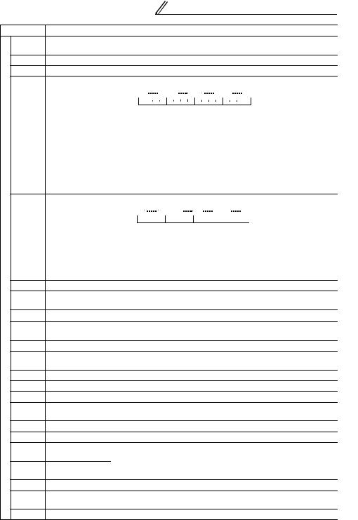
Number
D9159
D9160
D9161
D9162
controlfor |
D9163 |
|
|
||
registers |
D9164 |
|
|
||
Special |
D9165 |
|
D9166 |
||
|
||
|
D9167 |
|
|
D9169 |
|
|
D9170 |
|
|
D9171 |
|
|
D9172 |
|
|
D9179 |
|
|
D9180 |
|
|
D9181 |
|
|
D9182 |
|
|
D9197 |
|
|
D9198 |
|
|
D9199 |
|
|
D9200 |
|
|
D9201 |
|
|
|
|
|
|
|
|
|
|
|
|
|
|
|
|
|
|
|
|
|
|
|
|
|
|
|
|
|
|
|
Device Map |
|
|
||||
Name |
|
|
|
|
|
|
|
|
|
|
Description |
|
|
|
|
|
|
|
|
|
|
|
Page |
|
|
|
|||||||||||
|
|
|
|
|
|
|
|
|
|
|
|
|
|
|
|
|
|
|
|
|
|
||||||||||||||||
Converter output |
0.1V units |
|
|
|
|
|
|
|
|
|
|
|
|
|
|
|
|
|
|
|
|
|
|
|
|
|
|
— |
|
|
|
|
|||||
voltage peak value |
|
|
|
|
|
|
|
|
|
|
|
|
|
|
|
|
|
|
|
|
|
|
|
|
|
|
|
|
|
||||||||
Input power |
0.01kW/0.1kW units |
|
|
|
|
|
|
|
|
|
|
|
|
|
|
|
|
|
|
|
|
|
|
— |
|
|
|
||||||||||
Output power |
0.01kW/0.1kW units |
|
|
|
|
|
|
|
|
|
|
|
|
|
|
|
|
|
|
|
|
|
|
— |
|
|
|
||||||||||
|
Input terminal status details |
|
|
|
|
|
|
|
|
|
|
|
|
|
|
|
|
|
|
|
|
|
|
||||||||||||||
|
|
|
|
|
|
|
|
|
|
|
|
|
|
|
|
|
|
|
|
|
|
|
|
|
|
|
|
|
|
|
|||||||
|
|
|
B15 |
B12B11 |
B8B7 |
B4B3 |
B0 |
|
|
|
|
|
0:OFF |
|
|
|
|
|
|
|
|||||||||||||||||
|
|
|
|
|
|
|
|
|
|
|
|
|
|
|
|
|
|
|
|
|
|
|
|
|
|
|
|
|
|
|
|
|
|
|
|
|
|
|
|
|
|
|
|
|
|
|
|
|
|
|
|
|
|
|
|
|
|
|
|
|
|
|
|
|
|
|
|
1:ON |
|
|
|
|
|
|
|
|
|
|
|
|
|
|
|
|
|
|
|
|
|
|
|
|
|
|
|
|
|
|
|
|
|
|
|
|
|||||||||
|
|
|
|
|
|
|
|
|
|
|
|
|
|
|
|
|
|
|
|
|
|
|
|
|
|
|
|
|
|
STF |
|
|
|
|
|
|
|
|
|
|
|
|
|
|
|
|
|
|
|
|
|
|
|
|
|
|
|
|
|
|
|
|
|
|
|
|
|
|
|
|
|
|
|
||
Input terminal |
|
|
|
|
|
|
|
|
|
|
|
|
|
|
|
|
|
|
|
|
|
|
|
|
|
|
|
|
|
STR |
|
|
|
|
|
|
|
|
|
|
|
|
|
|
|
|
|
|
|
|
|
|
|
|
|
|
|
|
|
|
|
|
|
|
|
|
|
|
|
|
|
|
|
||
|
|
|
|
|
|
|
|
|
|
|
|
|
|
|
|
|
|
|
|
|
|
|
|
|
|
|
|
|
AU |
|
|
— |
|
|
|
|
|
|
|
|
|
|
|
|
|
|
|
|
|
|
|
|
|
|
|
|
|
|
|
|
|
|
|
|
|
|
|
|
|
|
|
|
|
||
status |
|
|
|
|
|
|
|
|
|
|
|
|
|
|
|
|
|
|
|
|
|
|
|
|
|
|
|
|
|
RT |
|
|
|
|
|
||
|
|
|
|
|
|
|
|
|
|
|
|
|
|
|
|
|
|
|
|
|
|
|
|
|
|
|
|
|
|
|
|
|
|
|
|||
|
|
|
|
|
|
|
|
|
|
|
|
|
|
|
|
|
|
|
|
|
|
|
|
|
|
|
|
|
RL |
|
|
|
|
|
|
|
|
|
|
|
|
|
|
|
|
|
|
|
|
|
|
|
|
|
|
|
|
|
|
|
|
|
|
|
|
|
|
|
|
|
|
|
|
||
|
|
|
|
|
|
|
|
|
|
|
|
|
|
|
|
|
|
|
|
|
|
|
|
|
|
|
|
|
|
RM |
|
|
|
|
|
|
|
|
|
|
|
|
|
|
|
|
|
|
|
|
|
|
|
|
|
|
|
|
|
|
|
|
|
|
|
|
|
|
|
|
|
|
|||
|
|
|
|
|
|
|
|
|
|
|
|
|
|
|
|
|
|
|
|
|
|
|
|
|
|
|
|
|
|
RH |
|
|
|
|
|
|
|
|
|
|
|
|
|
|
|
|
|
|
|
|
|
|
|
|
|
|
|
|
|
|
|
|
|
|
|
|
|
|
|
|
|
|
|||
|
|
|
|
|
|
|
|
|
|
|
|
|
|
|
|
|
|
|
|
|
|
|
|
|
|
|
|
|
|
JOG |
|
|
|
|
|
|
|
|
|
|
|
|
|
|
|
|
|
|
|
|
|
|
|
|
|
|
|
|
|
|
|
|
|
|
|
|
|
|
|
|
|
|
|||
|
|
|
|
|
|
|
|
|
|
|
|
|
|
|
|
|
|
|
|
|
|
|
|
|
|
|
|
|
|
MRS |
|
|
|
|
|
|
Map |
|
|
|
|
|
|
|
|
|
|
|
|
|
|
|
|
|
|
|
|
|
|
|
|
|
|
|
|
|
|
|
|
|
|
||||
|
|
|
|
|
|
|
|
|
|
|
|
|
|
|
|
|
|
|
|
|
|
|
|
|
|
|
|
|
|
STOP |
|
|
|
|
|
|
|
|
|
|
|
|
|
|
|
|
|
|
|
|
|
|
|
|
|
|
|
|
|
|
|
|
|
|
|
|
|
|
|
|
|
||||
|
|
|
|
|
|
|
|
|
|
|
|
|
|
|
|
|
|
|
|
|
|
|
|
|
|
|
|
|
|
CS |
|
|
|
|
|
|
|
|
|
|
|
|
|
|
|
|
|
|
|
|
|
|
|
|
|
|
|
|
|
|
|
|
|
|
|
|
|
RES |
|
|
|
|
|
|
Device |
|
Output terminal status details |
|
|
|
|
0:OFF |
|
|
|
|
|
|
|||||||||||||||||||||||||
|
|
|
|
|
|
|
|
|
|
|
|
|
|
|
|
|
|||||||||||||||||||||
|
|
|
|
|
|
|
|
|
|
|
|
|
|
|
|
|
|
|
|
|
|
|
|
||||||||||||||
|
|
B15 |
|
|
|
|
|
|
B7 |
B4B3 |
B0 |
|
|
|
|
|
|
|
|
|
|||||||||||||||||
Output terminal |
|
|
|
|
|
|
|
|
|
|
|
|
|
|
|
|
|
|
|
|
|
|
|
|
|
1:ON |
|
|
— |
|
|
|
|
||||
|
|
|
|
|
|
|
|
|
|
|
|
|
|
|
|
|
|
|
|
|
|
|
|
|
|
|
|
|
|
|
|||||||
|
|
|
|
|
|
|
|
|
|
|
|
|
|
|
|
|
|
|
|
|
|
|
|
|
|
|
|
|
|
||||||||
|
|
|
|
|
|
|
|
|
|
|
|
|
|
|
|
|
|
|
|
|
|
|
|
|
|
|
|
|
RUN |
|
|
|
|
|
|
||
status |
|
|
|
|
|
|
|
|
|
|
|
|
|
|
|
|
|
|
|
|
|
|
|
|
|
|
|
|
|
SU |
|
|
|
|
|
|
|
|
|
|
|
|
|
|
|
|
|
|
|
|
|
|
|
|
|
|
|
|
|
|
|
|
|
|
|
|
|
|
|
|
|
|
|
|
|
|
|
|
|
|
|
|
|
|
|
|
|
|
|
|
|
|
|
|
|
|
|
|
|
|
|
|
|
|
|
IPF |
|
|
|
|
|
|
|
|
|
|
|
|
|
|
|
|
|
|
|
|
|
|
|
|
|
|
|
|
|
|
|
|
|
|
|
|
|
OL |
|
|
|
|
|
|
|
|
|
|
|
|
|
|
|
|
|
|
|
|
|
|
|
|
|
|
|
|
|
|
|
|
|
|
|
|
|
|
|
|
|
|
|
|
|
|
|
|
|
|
|
|
|
|
|
|
|
|
|
|
|
|
|
|
|
|
|
|
|
|
|
|
|
|
|
FU |
|
|
|
|
|
|
|
|
|
|
|
|
|
|
|
|
|
|
|
|
|
|
|
|
|
|
|
|
|
|
|
|
|
|
|
|
|
|
|
|
|
|
|
|
|
|
|
|
|
|
|
|
|
|
|
|
|
|
|
|
|
|
|
|
|
|
|
|
|
|
|
|
|
|
|
ABC1 |
|
|
|
|
|
|
|
|
|
|
|
|
|
|
|
|
|
|
|
|
|
|
|
|
|
|
|
|
|
|
|
|
|
|
|
|
|
|
|
|
|
|
|
|
|
Load meter |
0.1% units |
|
|
|
|
|
|
|
|
|
|
|
|
|
|
|
|
|
|
|
|
|
|
|
ABC2 |
|
|
— |
|
|
|
|
|||||
|
|
|
|
|
|
|
|
|
|
|
|
|
|
|
|
|
|
|
|
|
|
|
|
|
|
|
|
|
|||||||||
|
|
|
|
|
|
|
|
|
|
|
|
|
|
|
|
|
|
|
|
|
|
|
|
|
|
|
|
|
|||||||||
Motor excitation |
0.01A/0.1A units *7 |
|
|
|
|
|
|
|
|
|
|
|
|
|
|
|
|
|
|
|
|
|
|
— |
|
|
|
|
|||||||||
current |
|
|
|
|
|
|
|
|
|
|
|
|
|
|
|
|
|
|
|
|
|
|
|
|
|
||||||||||||
|
|
|
|
|
|
|
|
|
|
|
|
|
|
|
|
|
|
|
|
|
|
|
|
|
|
|
|
|
|
|
|
|
|
|
|
|
|
Position pulse |
|
|
|
|
|
|
|
|
|
|
|
|
|
|
|
|
|
|
|
|
|
|
|
|
|
|
|
|
|
|
|
|
— |
|
|
|
|
Cumulative |
1h units |
|
|
|
|
|
|
|
|
|
|
|
|
|
|
|
|
|
|
|
|
|
|
|
|
|
|
— |
|
|
|
|
|||||
|
|
|
|
|
|
|
|
|
|
|
|
|
|
|
|
|
|
|
|
|
|
|
|
|
|
|
|
|
|
||||||||
energization time |
|
|
|
|
|
|
|
|
|
|
|
|
|
|
|
|
|
|
|
|
|
|
|
|
|
|
|
|
1 |
||||||||
— |
Always 0 |
|
|
|
|
|
|
|
|
|
|
|
|
|
|
|
|
|
|
|
|
|
|
|
|
|
|
— |
|
|
|
||||||
|
|
|
|
|
|
|
|
|
|
|
|
|
|
|
|
|
|
|
|
|
|
|
|
|
|
|
|
|
|||||||||
Actual operation |
1h unit |
|
|
|
|
|
|
|
|
|
|
|
|
|
|
|
|
|
|
|
|
|
|
|
|
|
|
— |
|
|
|
||||||
time |
|
|
|
|
|
|
|
|
|
|
|
|
|
|
|
|
|
|
|
|
|
|
|
|
|
|
|
|
|
|
|
|
|
|
|
|
FUNCTION |
Motor load factor |
0.1% units |
|
|
|
|
|
|
|
|
|
|
|
|
|
|
|
|
|
|
|
|
|
|
|
|
|
|
— |
|
|
|
||||||
|
|
|
|
|
|
|
|
|
|
|
|
|
|
|
|
|
|
|
|
|
|
|
|
|
|
|
|
|
|||||||||
Cumulative power |
1kW unit |
|
|
|
|
|
|
|
|
|
|
|
|
|
|
|
|
|
|
|
|
|
|
|
|
|
|
— |
|
|
|
||||||
Torque command |
0.1% units |
|
|
|
|
|
|
|
|
|
|
|
|
|
|
|
|
|
|
|
|
|
|
|
|
|
|
— |
|
|
PLC |
||||||
Torque current |
0.1% units |
|
|
|
|
|
|
|
|
|
|
|
|
|
|
|
|
|
|
|
|
|
|
|
|
|
|
— |
|
|
|
||||||
command |
|
|
|
|
|
|
|
|
|
|
|
|
|
|
|
|
|
|
|
|
|
|
|
|
|
|
|
|
|
||||||||
|
|
|
|
|
|
|
|
|
|
|
|
|
|
|
|
|
|
|
|
|
|
|
|
|
|
|
|
|
|
|
|
|
|
|
|
|
|
Motor output |
0.01kW units |
|
|
|
|
|
|
|
|
|
|
|
|
|
|
|
|
|
|
|
|
|
|
|
|
|
|
— |
|
|
|
||||||
Feedback pulse |
1 unit |
|
|
|
|
|
|
|
|
|
|
|
|
|
|
|
|
|
|
|
|
|
|
|
|
|
|
— |
|
|
|
||||||
Power saving |
|
|
|
|
|
|
|
|
|
|
|
|
|
|
|
|
|
|
|
|
|
|
|
|
|
|
|
|
|
|
|
|
— |
|
|
|
|
effect |
Variable according to parameters |
|
|
|
|
|
|
|
|
|
|
|
|
|
|
||||||||||||||||||||||
|
|
|
|
|
|
|
|
|
|
|
|
|
|
|
|
||||||||||||||||||||||
Cumulative |
|
|
|
|
|
|
|
|
|
|
|
— |
|
|
|
|
|||||||||||||||||||||
|
|
|
|
|
|
|
|
|
|
|
|
|
|
|
|
|
|
|
|
|
|
|
|
|
|
|
|
|
|
|
|
|
|
|
|
||
saving power |
|
|
|
|
|
|
|
|
|
|
|
|
|
|
|
|
|
|
|
|
|
|
|
|
|
|
|
|
|
|
|
|
|
|
|
||
|
|
|
|
|
|
|
|
|
|
|
|
|
|
|
|
|
|
|
|
|
|
|
|
|
|
|
|
|
|
|
|
|
|
|
|
|
|
PID set point |
0.1% units |
|
|
|
|
|
|
|
|
|
|
|
|
|
|
|
|
|
|
|
|
|
|
|
|
|
|
— |
|
|
|
||||||
PID measured |
0.1% units |
|
|
|
|
|
|
|
|
|
|
|
|
|
|
|
|
|
|
|
|
|
|
|
|
|
|
— |
|
|
|
|
|||||
value |
|
|
|
|
|
|
|
|
|
|
|
|
|
|
|
|
|
|
|
|
|
|
|
|
|
|
|
|
|
||||||||
|
|
|
|
|
|
|
|
|
|
|
|
|
|
|
|
|
|
|
|
|
|
|
|
|
|
|
|
|
|
|
|
|
|
|
|
|
|
PID deviation |
0.1% units |
|
|
|
|
|
|
|
|
|
|
|
|
|
|
|
|
|
|
|
|
|
|
|
|
|
|
— |
|
|
|
||||||
|
|
|
|
|
|
|
|
|
|
|
|
|
|
|
|
|
|
|
|
|
|
|
|
|
|
|
|
|
|
|
17 |
|
|||||
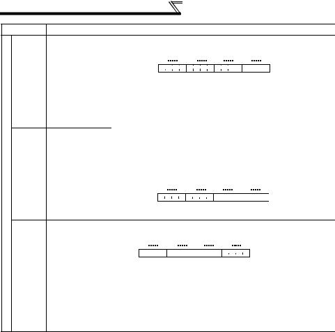
Device Map
Number
D9205
for control |
D9206 |
|
Special registers |
||
|
D9207
Name |
|
|
|
|
|
|
|
|
|
Description |
|
|
|
|
|
|
|
|
|
|
|
|
|
|
|
|
|
Page |
|||||||
|
The input status of the FR-A7AX is stored. |
|
|||||||||||||||||||||||||||||||||
|
All off (0) when an option is not fitted. |
|
|
|
|
|
|
|
|
|
|
|
|
|
|
||||||||||||||||||||
|
|
|
|
|
|
|
|
|
|
|
|
|
|
|
|
|
|
|
|
|
|
|
|
|
|
|
|
|
|
|
|
|
|
||
|
|
|
|
|
B15 |
|
B12B11 |
B8B7 |
B4B3 |
|
|
|
|
|
|
|
B0 |
|
|
0:OFF |
|
||||||||||||||
|
D9205 |
|
|
|
|
|
|
|
|
|
|
|
|
|
|
|
|
|
|
|
|
|
|
|
|
|
|
|
|
|
|
|
|||
|
|
|
|
|
|
|
|
|
|
|
|
|
|
|
|
|
|
|
|
||||||||||||||||
Option input |
|
|
|
|
|
|
|
|
|
|
|
|
|
|
|
|
|
|
|
|
|
|
|
|
|
|
|
|
|
|
1:ON |
— |
|||
|
|
|
|
|
|
|
|
|
|
|
|
|
|
|
|
|
|
|
|
|
|
|
|
|
|
|
|
|
|
|
|
|
|||
|
|
|
|
|
|
|
|
|
|
|
|
|
|
|
|
|
|
|
|
|
|
|
|
|
|
|
|
|
|
|
|
|
|
||
terminal status 1 |
|
|
|
|
|
|
|
|
|
|
|
|
|
|
|
|
|
|
|
|
|
|
|
|
|
|
|
|
|
|
|
|
|
X0 |
|
|
|
|
|
|
|
|
|
|
|
|
|
|
|
|
|
|
|
|
|
|
|
|
|
|
|
|
|
|
|
|
|
||||
|
|
|
|
|
|
|
|
|
|
|
|
|
|
|
|
|
|
|
|
|
|
|
|
|
|
|
|
|
|
|
|
|
X1 |
|
|
|
|
|
|
|
|
|
|
|
|
|
|
|
|
|
|
|
|
|
|
|
|
|
|
|
|
|
|
|
|
|
|
|
|
|
|
|
|
|
|
|
|
|
|
|
|
|
|
|
|
|
|
|
|
|
|
|
|
|
|
|
|
|
|
|
|
|
|
|
|
X2 |
|
|
|
|
|
|
|
|
|
|
|
|
|
|
|
|
|
|
|
|
|
|
|
|
|
|
|
|
|
|
|
|
|
|
|
|
|
|
|
|
|
|
|
|
|
|
|
|
|
|
|
|
|
|
|
|
|
|
|
|
|
|
|
|
|
|
|
|
|
|
|
X3 |
|
|
|
|
|
|
|
|
|
|
|
|
|
|
|
|
|
|
|
|
|
|
|
|
|
|
|
|
|
|
|
|
|
|
|
|
|
|
|
|
|
|
|
|
|
|
|
|
|
|
|
|
|
|
|
|
|
|
|
|
|
|
|
|
|
|
|
|
|
|
|
X4 |
|
|
|
|
|
|
|
|
|
|
|
|
|
|
|
|
|
|
|
|
|
|
|
|
|
|
|
|
|
|
|
|
|
|
|
|
|
|
|
|
|
|
|
|
|
|
|
|
|
|
|
|
|
|
|
|
|
|
|
|
|
|
|
|
|
|
|
|
|
|
|
X5 |
|
|
|
|
|
|
|
|
|
|
|
|
|
|
|
|
|
|
|
|
|
|
|
|
|
|
|
|
|
|
|
|
|
|
|
|
|
|
|
|
|
|
|
|
|
|
|
|
|
|
|
|
|
|
|
|
|
|
|
|
|
|
|
|
|
|
|
|
|
|
|
X6 |
|
|
|
|
|
|
|
|
|
|
|
|
|
|
|
|
|
|
|
|
|
|
|
|
|
|
|
|
|
|
|
|
|
|
|
|
|
|
|
|
|
|
|
|
|
|
|
|
|
|
|
|
|
|
|
|
|
|
|
|
|
|
|
|
|
|
|
|
|
|
|
X7 |
|
|
|
|
|
|
|
|
|
|
|
|
|
|
|
|
|
|
|
|
|
|
|
|
|
|
|
|
|
|
|
|
|
|
|
|
|
|
|
|
|
|
|
|
|
|
|
|
|
|
|
|
|
|
|
|
|
|
|
|
|
|
|
|
|
|
|
|
|
|
|
X8 |
|
|
|
|
|
|
|
|
|
|
|
|
|
|
|
|
|
|
|
|
|
|
|
|
|
|
|
|
|
|
|
|
|
|
|
|
|
|
|
|
|
|
|
|
|
|
|
|
|
|
|
|
|
|
|
|
|
|
|
|
|
|
|
|
|
|
|
|
|
|
|
X9 |
|
|
|
|
|
|
|
|
|
|
|
|
|
|
|
|
|
|
|
|
|
|
|
|
|
|
|
|
|
|
|
|
|
|
|
|
|
|
|
|
|
|
|
|
|
|
|
|
|
|
|
|
|
|
|
|
|
|
|
|
|
|
|
|
|
|
|
|
|
|
|
X10 |
|
|
|
|
|
|
|
|
|
|
|
|
|
|
|
|
|
|
|
|
|
|
|
|
|
|
|
|
|
|
|
|
|
|
|
|
|
|
|
|
|
|
|
|
|
|
|
|
|
|
|
|
|
|
|
|
|
|
|
|
|
|
|
|
|
|
|
|
|
|
|
X11 |
|
|
|
|
|
|
|
|
|
|
|
|
|
|
|
|
|
|
|
|
|
|
|
|
|
|
|
|
|
|
|
|
|
|
|
|
|
Option input |
|
|
|
|
|
|
|
|
|
|
|
|
|
|
|
|
|
|
|
|
|
|
|
|
|
|
|
|
|
|
|
|
|
X12 |
|
|
|
|
|
|
|
|
|
|
|
|
|
|
|
|
|
|
|
|
|
|
|
|
|
|
|
|
|
|
|
|
|
|
|
||
|
|
|
|
|
|
|
|
|
|
|
|
|
|
|
|
|
|
|
|
|
|
|
|
|
|
|
|
|
|
|
|
|
X13 |
— |
|
|
|
|
|
|
|
|
|
|
|
|
|
|
|
|
|
|
|
|
|
|
|
|
|
|
|
|
|
|
|
|
|
|
|
||
terminal status 2 |
|
|
|
|
|
|
|
|
|
|
|
|
|
|
|
|
|
|
|
|
|
|
|
|
|
|
|
|
|
|
|
|
|
X14 |
|
|
|
|
|
|
|
|
|
|
|
|
|
|
|
|
|
|
|
|
|
|
|
|
|
|
|
|
|
|
|
|
|
|
|||
|
|
|
|
|
|
|
|
|
|
|
|
|
|
|
|
|
|
|
|
|
|
|
|
|
|
|
|
|
|
|
|
|
X15 |
|
|
|
|
|
|
|
|
|
|
|
|
|
|
|
|
|
|
|
|
|
|
|
|
|
|
|
|
|
|
|
|
|
|
|
|
||
|
|
|
|
|
|
|
|
|
|
|
|
|
|
|
|
|
|
|
|
|
|
|
|
|
|
|
|
|
|
|
|||||
|
|
|
|
B15 |
B12B11 |
B8B7 |
B4B3 |
|
|
|
|
|
|
|
B0 |
|
0:OFF |
|
|||||||||||||||||
|
D9206 |
|
|
|
|
|
|
|
|
|
|
|
|
|
|
|
|
|
|
|
|
|
|
|
|
|
|
|
|
|
|
||||
|
|
|
|
|
|
|
|
|
|
|
|
|
|
|
|
|
|
|
|
|
|
|
|
|
|
|
|
|
|
1:ON |
|
||||
|
|
|
|
|
|
|
|
|
|
|
|
|
|
|
|
|
|
|
|
|
|
|
|
|
|
|
|
|
|
|
|
|
|
||
|
|
|
|
|
|
|
|
|
|
|
|
|
|
|
|
|
|
|
|
|
|
|
|
|
|
|
|
|
|
|
|
|
|
DY |
|
|
|
|
|
|
|
|
|
|
|
|
|
|
|
|
|
|
|
|
|
|
|
|
|
|
|
|
|
|
|
|
|
|
|
|
|
|
The output status of the FR-A7AY, FR-A7AR is stored. |
|
|||||||||||||||||||||||||||||||||
|
All off (0) when an option is not fitted. |
|
|
|
|
|
|
|
|
|
|
|
|
|
|
||||||||||||||||||||
|
|
|
|
|
|
|
|
|
|
|
|
|
|
|
|
|
|
|
|
|
|
|
|
|
|
|
|
|
|||||||
|
|
B15 |
B12B11 |
|
B8B7 |
|
B4B3 |
|
|
B0 |
|
|
|
|
|
|
|
0:OFF |
|
||||||||||||||||
|
|
|
|
|
|
|
|
|
|
|
|
|
|
|
|
|
|
|
|
|
|
|
|
|
|
|
|
|
|
||||||
|
|
|
|
|
|
|
|
|
|
|
|
|
|
|
|
|
|
|
|
|
|
|
|
|
|
|
|
|
1:ON |
|
|||||
|
|
|
|
|
|
|
|
|
|
|
|
|
|
|
|
|
|
|
|
|
|
|
|||||||||||||
Option output |
|
|
|
|
|
|
|
|
|
|
|
|
|
|
|
|
|
|
|
|
|
|
|
|
|
|
|
|
Y0 |
— |
|||||
|
|
|
|
|
|
|
|
|
|
|
|
|
|
|
|
|
|
|
|
|
|
|
|
|
|
|
|||||||||
|
|
|
|
|
|
|
|
|
|
|
|
|
|
|
|
|
|
|
|
|
|
|
|
|
|
|
|
Y1 |
|||||||
terminal status |
|
|
|
|
|
|
|
|
|
|
|
|
|
|
|
|
|
|
|
|
|
|
|
|
|
|
|
|
Y2 |
||||||
|
|
|
|
|
|
|
|
|
|
|
|
|
|
|
|
|
|
|
|
|
|
|
|
|
|
|
|
|
|||||||
|
|
|
|
|
|
|
|
|
|
|
|
|
|
|
|
|
|
|
|
|
|
|
|
|
|
|
|
|
Y3 |
|
|||||
|
|
|
|
|
|
|
|
|
|
|
|
|
|
|
|
|
|
|
|
|
|
|
|
|
|
|
|
|
|
||||||
|
|
|
|
|
|
|
|
|
|
|
|
|
|
|
|
|
|
|
|
|
|
|
|
|
|
|
|
|
Y4 |
|
|||||
|
|
|
|
|
|
|
|
|
|
|
|
|
|
|
|
|
|
|
|
|
|
|
|
|
|
|
|
|
|
||||||
|
|
|
|
|
|
|
|
|
|
|
|
|
|
|
|
|
|
|
|
|
|
|
|
|
|
|
|
|
Y5 |
|
|||||
|
|
|
|
|
|
|
|
|
|
|
|
|
|
|
|
|
|
|
|
|
|
|
|
|
|
|
|
|
|
||||||
|
|
|
|
|
|
|
|
|
|
|
|
|
|
|
|
|
|
|
|
|
|
|
|
|
|
|
|
|
Y6 |
|
|||||
|
|
|
|
|
|
|
|
|
|
|
|
|
|
|
|
|
|
|
|
|
|
|
|
|
|
|
|
|
|
||||||
|
|
|
|
|
|
|
|
|
|
|
|
|
|
|
|
|
|
|
|
|
|
|
|
|
|
|
|
|
RA1 |
|
|||||
|
|
|
|
|
|
|
|
|
|
|
|
|
|
|
|
|
|
|
|
|
|
|
|
|
|
|
|
|
|
||||||
|
|
|
|
|
|
|
|
|
|
|
|
|
|
|
|
|
|
|
|
|
|
|
|
|
|
|
|
|
RA2 |
|
|||||
|
|
|
|
|
|
|
|
|
|
|
|
|
|
|
|
|
|
|
|
|
|
|
|
|
|
|
|
|
|
||||||
|
|
|
|
|
|
|
|
|
|
|
|
|
|
|
|
|
|
|
|
|
|
|
|
|
|
|
|
|
RA3 |
|
|||||
|
|
|
|
|
|
|
|
|
|
|
|
|
|
|
|
|
|
|
|
|
|
|
|
|
|
|
|
|
|
||||||
|
|
|
|
|
|
|
|
|
|
|
|
|
|
|
|
|
|
|
|
|
|
|
|
|
|
|
|
|
|
|
|
|
|
|
|
18

Device Map
Number
|
D9234 |
|
|
D9235 |
|
|
D9236 |
|
|
D9237 |
|
|
D9238 |
|
|
D9239 |
|
|
D9240 |
|
controlfor |
D9241 |
|
D9242 |
||
registers |
||
D9243 |
||
|
||
Special |
D9244 |
|
D9245 |
||
|
D9246 |
|
|
D9247 |
|
|
D9248 |
|
|
D9249 |
|
|
D9250 |
|
|
D9251 |
|
|
D9252 |
|
|
D9253 |
|
|
D9254 |
|
|
D9255 |
|
|
|
Name |
Description |
Page |
|
|
|
Second |
|
|
|
|
|
parameter |
When setting the calibration(bias/gain) parameters. |
|
|
|
|
changing (RAM) |
|
|
|
|
|
Second |
H00: Frequency(toruque) |
34, 36 |
|
|
|
H01: Parameter-set analog value |
|
|
|
||
parameter |
H02: Analog value input from terminal |
|
|
|
|
changing |
|
|
|
|
|
(EEPROM) |
|
|
|
|
|
Pulse train input |
The number of pulses counted in count cycle is |
|
|
|
|
sampling pulse |
stored. (0 to 32767) |
|
|
|
|
Pulse train input |
|
|
|
|
|
cumulative count |
|
|
|
|
|
value L |
The cumulative value of the number of sampling |
|
|
|
|
Pulse train input |
pulses is stored. (0 to 99999999) |
40 |
|
|
|
cumulative count |
|
|
|
|
|
value H |
|
|
|
|
|
Reset request of |
The sampling pulses and cumulative count value are |
|
|
|
Map |
pulse train input |
cleared. Automatically changes to "0" after reset. |
|
|
|
|
count |
(1: count clear) |
|
|
|
Device |
Count start of the |
Start counting the sampling pulses and cumulative |
|
|
|
|
pulse train input |
count value. (0: count stop, 1: count start) |
|
|
|
|
Parameter |
Set the number of parameter read or written of the |
|
|
|
|
number (RAM) |
inverter. |
|
|
|
|
Parameter |
The parameter description of the inverter (RAM value) |
|
|
|
|
description |
specified by D9241 is stored. Set the parameter |
|
|
|
|
|
|
|
|
||
(RAM) |
setting for parameter write. |
34, 36 |
|
|
|
Parameter |
Set the number of parameter read or written of the |
|
|
|
|
number |
|
|
|
|
|
inverter. |
|
|
|
|
|
(EEPROM) |
|
|
|
|
|
|
|
|
|
|
|
Parameter |
The parameter description of the inverter (EEPROM |
|
|
|
|
description |
value) specified by D9243 is stored. Set the |
|
|
|
|
(EEPROM) |
parameter setting for parameter write. |
|
|
|
|
Terminal 1 input |
Analog input value of terminal 1 (0.1% increments) is |
|
|
|
|
stored. |
|
|
|
1 |
|
|
|
|
|
||
Terminal 2 input |
Analog input value of terminal 2 (0.1% increments) is |
39 |
|
|
|
|
stored. |
|
|
|
|
Terminal 4 input |
Analog input value of terminal 4 (0.1% increments) is |
|
|
|
|
|
|
|
|
||
stored. |
|
|
FUNCTION |
||
|
|
|
|||
PID set point / |
Set the PID set point or PID deviation (0.01% units) |
|
|
||
PID deviation |
|
|
|
|
|
|
|
|
|
|
|
PID |
Set the PID measurement value (0.01% units) |
41 |
|
PLC |
|
measurement |
|
||||
value |
|
|
|
||
|
|
|
|
|
|
PID manipulated |
Stores the PID manipulated variable (0.01% units) |
|
|
|
|
variable |
|
|
|
|
|
Terminal FM |
When Pr. 54 is set to "70", pulse train can be output |
|
|
|
|
from terminal FM. High speed pulse train output can |
|
|
|
|
|
output |
|
|
|
|
|
be performed. (0.1% increments) |
|
|
|
|
|
|
|
|
|
|
|
Terminal AM |
When Pr. 158 is set to "70", analog output can be |
39 |
|
|
|
output |
performed from terminal AM. (0.1% increments) |
|
|
|
|
AM0 output |
Analog output can be performed from terminal AM0 |
|
|
|
|
AM1 output |
and AM1 of the FR-A7AY. (0.1% increments) |
|
|
|
|
PID operation |
Setting 1 starts PID control. |
41 |
|
|
|
control |
|
|
|
||
|
|
|
|
|
|
|
|
19 |
|
|
|

Inverter Status Monitoring, Special Registers for Control
1.7 Inverter Status Monitoring, Special Registers for Control
You can assign the data for grasping and changing the inverter's operation status to D9133 - D9147 and read/write them from the user sequence. (Refer to page 14 for the list.)
1.7.1Data that can be read at all times
The following data can always be read. They are automatically refreshed every time the END instruction is executed.
(1) Operation monitor
The following data devices are always read-enabled (write-disabled) to allow you to monitor the output frequency, output current and output voltage of the inverter. Note the setting units.
Device |
Name |
Setting |
Data Example |
Data Access Enable |
||
No. |
Unit |
Condition |
||||
|
|
|
||||
D9133 |
Output frequency |
0.01Hz |
Device data 6000 |
→ 60.00Hz |
|
|
monitor |
|
|||||
D9134 |
Output current |
0.01A |
Device data 200 → 2.00A |
Always |
||
|
monitor |
|
|
|
|
|
D9135 |
Output voltage |
0.1V |
Device data 1000 |
→ 100.0V |
|
|
|
monitor |
|
|
|
|
|
CAUTION
The frequency can be set in increments of 0.01Hz but actual operation is performed in increments of 0.1Hz.
20

Inverter Status Monitoring, Special Registers
for Control
(2) Error history (error codes and error definitions)
The inverter stores the error codes of the errors that occurred.
The error codes of up to eight errors are stored in the order as shown below and are always read-enabled (write-disabled).
<Error code storing method details>
D9136 |
b15 to b8 |
|
b7 to b0 |
||
Error history 2 |
Error history 1 |
||||
D9137 |
Error history 4 |
Error history 3 |
|||
D9138 |
|
|
|
|
|
Error history 6 |
Error history 5 |
||||
D9139 |
Error history 8 |
Error history 7 |
|||
|
|
|
|
|
|
|
|
Data |
Description |
|
|
|
|
H00 |
No alarm |
|
|
|
|
H10 |
E.OC1 |
|
|
|
|
H11 |
E.OC2 |
|
|
|
|
H12 |
E.OC3 |
|
|
|
|
H20 |
E.OV1 |
|
|
|
|
H21 |
E.OV2 |
|
|
|
|
H22 |
E.OV3 |
|
|
|
|
H30 |
E.THT |
|
|
|
|
H31 |
E.THM |
|
|
|
|
H40 |
E.FIN |
|
|
|
|
H50 |
E.IPF |
|
|
|
|
H51 |
E.UVT |
|
|
|
|
H52 |
E.ILF |
|
|
|
|
H60 |
E.OLT |
|
|
|
|
H70 |
E.BE |
|
|
|
|
H80 |
E.GF |
|
|
|
|
H81 |
E.LF |
|
|
Newer
Older
Data |
Description |
H90 |
E.OHT |
H91 |
E.PTC |
HA0 |
E.OPT |
HA3 |
E.OP3 |
HB0 |
E.PE |
HB1 |
E.PUE |
HB2 |
E.RET |
HB3 |
E.PE2 |
HC0 |
E.CPU |
HC1 |
E.CTE |
HC2 |
E.P24 |
HC4 |
E.CDO |
HC5 |
E.IOH |
HC6 |
E.SER |
HC7 |
E.AIE |
HC8 |
E.USB |
HD0 |
E.OS |
HD1 |
E.OSD |
Data |
Description |
HD2 |
E.ECT |
HD3 |
E.OD |
HD5 |
E.MB1 |
HD6 |
E.MB2 |
HD7 |
E.MB3 |
HD8 |
E.MB4 |
HD9 |
E.MB5 |
HDA |
E.MB6 |
HDB |
E.MB7 |
HDC |
E.EP |
HF1 |
E.1 |
HF2 |
E.2 |
HF3 |
E.3 |
HF6 |
E.6 |
HF7 |
E.7 |
HFB |
E.11 |
HFD |
E.13 |
Refer to the Inverter instruction manual (applied) for alarm definition details.
1
PLC FUNCTION
21
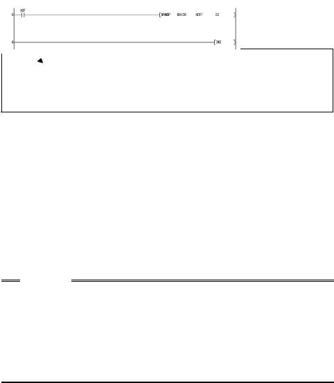
Inverter Status Monitoring, Special Registers for Control
<Alarm definition read program example>
The following program reads the latest alarm definition of the inverter to D0.
 Alarm definition read request
Stores only the lower 8 bits of error history 1, 2 (D9136) into D0.
(The latest error information is stored into D0.)
<Regarding the error No. and details of the self-diagnostic errors>
During execution of a sequence program, any of the following error No. is stored into D9008 due to an operation error.
At occurrence of a self-diagnostic error, the P.RUN indication (LED) flickers.
Error No. |
Error Name |
Details |
|
10 |
INSTRCT CODE ERR. |
There is an instruction code that cannot be decoded. |
|
Unusable device is specified. |
|||
|
|
||
11 |
PARAMETER ERR |
Main program capacity setting is over 1k step. |
|
Unusable function is set. |
|||
|
|
||
22 |
WDT ERR |
Scan time is longer than the time that can be monitored |
|
by the watchdog timer. |
|||
|
|
||
24 |
END NOT EXECUTE |
END instruction was not executed. |
CAUTION
1.For the LD, AND, OR, logical comparison operation and OUT instructions, device checks are always made. For the other instructions (SET, RST, MOV, etc.), however, device checks are made when the execution condition holds.
2.Operation at error stop The outputs (Y) are cleared.
The other devices hold the states prior to an error stop.
When you want to clear them, power off or reset (short RES-SD (0.1s), then open) the inverter.
22
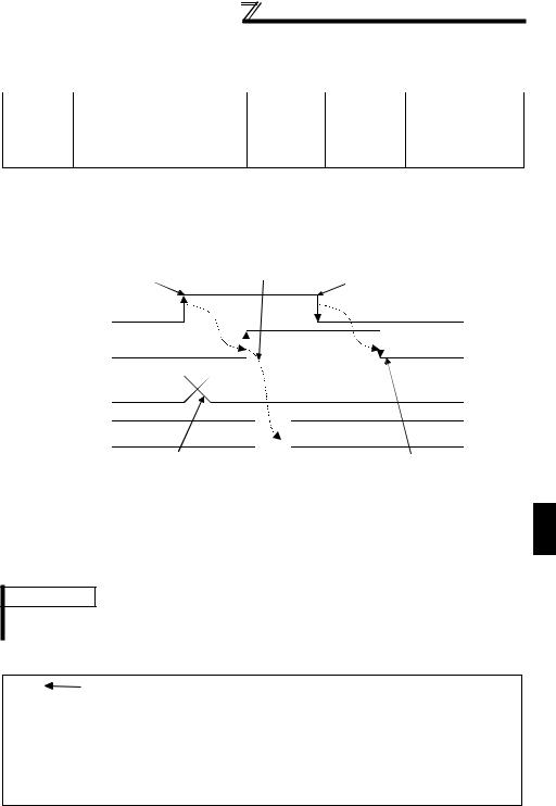
Inverter Status Monitoring, Special Registers
for Control
1.7.2Data that are read by controlling (OFF to ON) the read
command
You can read the operation mode and set frequency of the inverter.
Device |
Name |
Read |
Write |
Data Access |
|
No. |
Command |
Completion |
Enable Condition |
||
|
|||||
D9140 |
Operation mode setting read |
Y20 |
X20 |
Always |
|
D9141 |
Set frequency read (RAM) |
Y21 |
X21 |
||
D9142 |
Set frequency read (EEPROM) |
Y22 |
X22 |
|
Data are stored into the above data devices as soon as the read completion turns from off to on after the read command has turned from off to on.
If the read command remains on, data is not refreshed. (Data is not updated.)
Turn the device off once, then on again to refresh data.
Data read timing chart
|
|
|
|
3) In user sequence, ON of read completion |
||
|
1) Read command is turned |
is confirmed and data is read from special |
||||
|
on in user sequence. |
register and processed. |
4) After completion of read, |
|||
|
|
|
|
|
|
|
|
|
|
|
|
|
read command is turned off. |
|
Y2n(n=0 to 2) |
|
|
|
|
|
|
Read command |
|
|
|
|
|
|
X2n(n=0 to 2) |
|
|
|
|
|
|
Read completion |
|
|
|
|
|
|
D914n(n=0 to 2) |
|
|
|
|
|
|
Read data |
|
|
|
|
|
|
User sequence |
|
|
|
|
|
|
processing |
|
|
|
|
|
|
|
2) Inverter CPU stores inverter data |
5) Inverter CPU confirms that |
|||
|
|
|
into special register and turns on |
read command is off and |
||
|
|
|
read completion. |
turns off read completion. |
||
(1) Operation mode setting read (D9140) |
|
|||||
|
Data Setting |
|
Operation Mode |
|
|
|
|
H0000 |
|
NET operation mode |
|
|
|
|
H0001 |
|
External operation mode |
|
|
|
|
H0002 |
|
PU operation mode |
|
|
|
REMARKS
When the Pr. 79 "operation mode selection" setting is other than "0", the operation mode is as set. However, when Pr. 79 = "3" or "4", the operation mode is "H0002" (PU operation mode).
<Operation mode setting read program example>
The following program reads the operation mode data to D0.
1
PLC FUNCTION
Operation mode read setting request
Turns on operation mode read request pulse.
Stores operation mode data to D0 when operation mode setting read completion signal turns on.
Turns on operation mode setting read command. (Until operation mode setting read completion signal turns on)
23
Inverter Status Monitoring, Special Registers for Control
(2)Set frequency (RAM) (D9141)
The frequency set to the RAM is read to D9141. The unit is 0.01Hz.
(For example, 6000 indicates 60.00Hz.)
When the speed is set, the speed is either 1r/min or 0.1r/min.
<Set frequency (RAM) read program example>
The following program reads the set frequency (RAM) to D0.
 Set frequency read (RAM) setting request
Turns on set frequency read (RAM) request pulse.
Stores data to D0 when set frequency read (RAM) completion signal turns on.
Turns on set frequency read (RAM) command. (Until set frequency read (RAM) completion signal turns on)
REMARKS
The read frequency is not the command value of the external signal.
(3)Set frequency (EEPROM) (D9142)
The frequency set to the EEPROM is read to D9142. The unit is 0.01Hz. (For example, 6000 indicates 60.00Hz.)
When the speed is set, the speed is either 1r/min or 0.1r/min.
<Set frequency read (EEPROM) program example>
The following program reads the set frequency (E2PROM) to D0.
The following program reads the set frequency (E2PROM) to D0.
Set frequency read (E2PROM) setting request
Stores data to D0 when set frequency read (E2PROM) completion signal turns on.
Turns on set frequency read (E2PROM) command. (Until set frequency read (E2PROM) completion signal turns on)
REMARKS
The read frequency is not the command value of the external signal.
24

Inverter Status Monitoring, Special Registers
for Control
1.7.3How to write data by controlling (OFF to ON) the write command
You can write the operation mode and set frequency to the inverter, batch-clear the alarm definitions, and clear all parameters.
Device |
Name |
Write |
Write |
Data Access |
|
No. |
Command |
Completion |
Enable Condition |
||
|
|||||
D9143 |
Operation mode setting write |
Y23 |
X23 |
Pr.79 =0, 2 |
|
D9144 |
Set frequency write (RAM) |
Y24 |
X24 |
PU operation mode |
|
|
Set frequency write |
|
|
(PU LED on) or CC- |
|
D9145 |
Y25 |
X25 |
Link operation mode |
||
(E2PROM) |
(PU and EXT LEDs |
||||
|
|
|
|||
|
|
|
|
flicker slowly) |
|
D9146 |
Alarm definition batch clear |
Y26 |
X26 |
Always |
|
D9147 |
All parameter clear |
Y27 |
X27 |
As set in Pr. 77 |
The above data are written as soon as the write completion turns on after the write command has turned from off to on.
(Alarm definition batch clear (D9146) and all parameter clear (D9147) turn on at completion of clear.)
To write the data again, the write command must be turned off once, then on again.
Data write timing chart
1) In user sequence, user |
2) In user sequence, write |
|
command is turned on. |
||
data is stored into write |
||
data area (D914n). |
|
Y2n(n=3 to 7)
Write command
X2n(n=3 to 7)
Write completion
D914n(n=3 to 7)
Write data
User data
3)Turns on when inverter CPU completes data write to inverter.
Alarm definition clear and parameter clear turn on at completion of clear.
0 written to D9150 indicates normal completion.
Any value other than 0 indicates abnormal completion.
1
PLC FUNCTION
25
Loading...