


OPERATOR'S MANUAL
MANUEL de L'UTILISATEUR
MANUAL del OPERADOR
Cat. No. No de Cat. Cat. No.
5337-20, 5337-21 
5339-20, 5339-21 
5340-20, 5340-21 

5342-20, 5342-21 
HEAVY-DUTY ROTARY HAMMERS AND DEMOLITION HAMMERS
EXTRA ROBUSTES MARTEAUX ROTATIFS ET MARTEAU DE DÉMOLISSEUR
ROTOMARTILLOS Y MARTILLOS PERFORADORES DE DEMOLICIÓN HEAVY-DUTY
TO REDUCE THE RISK OF INJURY, USER MUST READ OPERATOR'S MANUAL.
AFIN DE RÉDUIRE LE RISQUE DE BLESSURES, L'UTILISATEUR DOIT LIRE LE MANUEL DE L'UTILISATEUR. PARA REDUCIR EL RIESGO DE LESIONES, EL USUARIO DEBE LEER EL MANUAL DEL OPERADOR.
page 2

GENERAL SAFETY RULES — FOR ALL POWER TOOLS


 WARNING
READ ALL INSTRUCTIONS
Failure to follow all instructions listed below may result in electric shock, fire and/or serious injury. The term "power tool" in all of the warnings listed below refers to your mains-operated (corded) power tool or battery-opearted (cordless) power tool.
SAVE THESE INSTRUCTIONS
|
WORK AREA SAFETY |
|
|
|
POWER TOOL USE AND CARE |
|
|
|
|||||
|
|
|
|
|
|
|
|
|
|
|
|
|
|
1.Keep work area clean and well lit. Cluttered or dark areas invite accidents.
2.Do not operate power tools in explosive atmospheres, such as in the presence of flammable liquids, gases, or dust. Power tools create sparks which may ignite the dust or fumes.
3.Keep children and bystanders away while operating a power tool.
Distractions can cause you to lose control.
ELECTRICAL SAFETY
4.Power tool plugs must match the outlet. Never modify the plug in any way. Do not use any adapter plugs with earthed (grounded) power tools. Unmodified plugs and matching outlets will reduce risk of electric shock.
5.Avoid body contact with earthed or grounded surfaces such as pipes, radiators, ranges and refrigerators. There is an increased risk of electric shock if your body is earthed or grounded.
6.Do not expose power tools to rain or wet conditions. Water entering a power tool will increase the risk of electric shock.
7.Do not abuse the cord. Never use the cord for carrying, pulling, or unplugging the power tool. Keep cord away from heat, oil, sharp edges, or moving parts. Damaged or entangled cords increase the risk of electric shock.
8.When operating a power tool outdoors, use an extension cord suitable for outdoor use. Use of a cord suitable for outdoor use reduces the risk of electric shock.
PERSONAL SAFETY
9.Stay alert, watch what you are doing and use common sense when operating a power tool. Do not use a power tool while you are tired or under the influence of drugs, alcohol or medication. A moment of inattention while operating power tools may result in serious personal injury.
10.Use safety equipment. Always wear eye protection. Safety equipment such as dust mask, non-skid safety shoes, hard hat, or hearing protection used for appropriate conditions will reduce personal injuries.
11.Avoid accidental starting. Ensure the switch is in the off-position before plugging in. Carrying tools with your finger on the switch or plugging in power tools that have the switch on invites accidents.
12.Remove any adjusting key or wrench before turning the power tool on. A wrench or a key left attached to a rotating part of the power tool may result in personal injury.
13.Do not overreach. Keep proper footing and balance at all times. This enables better control of the power tool in unexpected situations.
14.Dress properly. Do not wear loose clothing or jewellery. Keep your hair, clothing and gloves away from moving parts. Loose clothes, jewellery, or long hair can be caught in moving parts.
15.If devices are provided for the connection of dust extraction and collection facilities, ensure these are connected and properly used.
Use of these devices can reduce dust-related hazards.
16.Do not force the power tool. Use the correct power tool for your application. The correct power tool will do the job better and safer at the rate for which it was designed.
17.Do not use the power tool if the switch does not turn it on and off.
Any power tool that cannot be controlled with the switch is dangerous and must be repaired.
18.Disconnect the plug from the power source and/or the battery pack from the power tool before making any adjustments, changing accessories, or storing power tools. Such preventive safety measures reduce the risk of starting the tool accidentally.
19.Store idle power tools out of the reach of children and do not allow persons unfamiliar with the power tools or these instructions to operate power tools. Power tools are dangerous in the hands of untrained users.
20.Maintain power tools. Check for misalignment or binding of moving parts, breakage of parts and any other condition that may affect the power tool's operation. If damaged, have the power tool repaired before use. Many accidents are caused by poorly maintained power tools.
21.Keep cutting tools sharp and clean. Properly maintained cutting tools with sharp cutting edges are less likely to bind and are easier to control.
22.Use the power tool, accessories and tool bits etc., in accordance with these instructions and in the manner intended for the particular type of power tool, taking into account the working conditions and the work to be performed. Use of the power tool for operations different from those intended could result in a hazardous situation.
SERVICE
23.Have your power tool serviced by a qualified repair person using only identical replacement parts. This will ensure that the safety of the power tool is maintained.
SPECIFIC SAFETY RULES
1.Hold power tools by insulated gripping surfaces when performing an operation where the cutting tool may contact hidden wiring or its own cord. Contact with a “live” wire will make exposed metal parts of the tool “live” and shock the operator.
2.Maintain labels and nameplates. These carry important information.
If unreadable or missing, contact a MILWAUKEE service facility for a free replacement.
3.WARNING! Some dust created by power sanding, sawing, grinding, drilling, and other construction activities contains chemicals known to cause cancer, birth defects or other reproductive harm. Some examples of these chemicals are:
•lead from lead-based paint
•crystalline silica from bricks and cement and other masonry products, and
•arsenic and chromium from chemically-treated lumber.
Your risk from these exposures varies, depending on how often you do this type of work. To reduce your exposure to these chemicals: work in a well ventilated area, and work with approved safety equipment, such as those dust masks that are specifically designed to filter out microscopic particles.
4.Wear ear protectors. Exposure to noise can cause hearing loss.
5.Use auxiliary handles supplied with the tool. Loss of control can cause personal injury.

Symbology
|
Double Insulated |
|
|
|
|
|
Volts Alternating Current |
|
|
|
|
|
Amps |
|
|
|
|
|
No Load Revolutions per |
|
|
Minute (RPM) |
|
BPM |
Blows per Minute (BPM) |
|
|
||
|
|
|
|
Underwriters Laboratories, Inc. |
|
|
|
|
|
Mexican Approvals Marking |
|
|
|
|
Specifications
|
|
|
|
|
|
Max |
Max |
|
|
|
|
|
|
|
Blows/ |
Percussion |
Percussion |
|
Chisel Shank |
Cat. |
Volts |
|
No Load |
Drill Bit |
Core Bit |
|
|||
No. |
AC |
Amps |
RPM * |
Minute |
Diameter |
Diameter † |
Chisels |
Type |
|
5337-20 |
120 |
14 |
|
-- |
975-1950* |
-- |
-- |
See |
3/4" Hex |
5337-21 |
120 |
14 |
|
-- |
975-1950* |
-- |
-- |
3/4" Hex |
|
|
"Chiseling |
||||||||
5339-20 |
120 |
14 |
|
-- |
975-1950* |
-- |
-- |
and |
SDS-Max |
5339-21 |
120 |
14 |
|
-- |
975-1950* |
-- |
-- |
Chipping" |
SDS-Max |
|
|
||||||||
5340-20 |
120 |
15 |
125 |
- 250 975-1950* |
2" Spline |
6" † |
|
3/4" Hex with |
|
|
|
|
|
|
|
|
|
|
21/32" Round |
5340-21 |
120 |
15 |
125 |
- 250 975-1950* |
2" Spline |
6" † |
|
3/4" Hex with |
|
|
|
|
|
|
|
|
|
|
21/32" Round |
5342-20 |
120 |
15 |
125 |
- 250 975-1950* 2" SDS-Max |
6" † |
|
SDS-Max |
||
5342-21 |
120 |
15 |
125 |
- 250 975-1950* 2" SDS-Max |
6" † |
|
SDS-Max |
||
*EFCC - The Electronic Feedback Control Circuit maintains constant speed under varying load conditions.
†Use MILWAUKEE core bits Cat. No. 48-20-5125 through 48-20-5165. Do not use LHS (Large Hole System) Components with rotary hammers 5340-20 and 5342-20. The bits could fail, breaking apart at the threaded stud and causing injury and property damage.
FUNCTIONAL DESCRIPTION
12 |
Cat. No. 5342-20 |
4 |
|
||
|
|
11 |
5 |
|
1.Vibration isolation system
2.On/Off trigger switch
3.Soft grip handle
4.Service indicator light
5.Speed control dial
6.Lock-on button (Cat. Nos. 5337-20, 5339-20 only)
11
9
7.Spade side handle (Cat. Nos. 5337-20, 5339-20 only)
8.Spade side handle adjusting knob (Cat. Nos. 5337-20, 5339-20 only)
9.Bit lock (Cat. Nos. 5337-20, 5340-20 only)
10. |
Straight side handle (must be used when hammering with rotation) |
8 |
|
11. |
Straight side handle mounting positions (3 locations) |
||
|
|||
12. |
Action selector (Cat. No. 5339-20, 5342-20 only) |
|
1
10
6
1
11
2
3
Cat. No. 5337-20
7
1
page 4
GROUNDING
WARNING
Improperly connecting the grounding wire can result in the risk of electric shock. Check with a qualified electrician if you are in doubt as to whether the outlet is properly grounded. Do not modify the plug provided with the tool. Never remove the grounding prong from the plug. Do not use the tool if the cord or plug is damaged. If damaged, have it repaired by a MILWAUKEE service facility before use. If the plug will not fit the outlet, have a proper outlet installed by a qualified electrician.
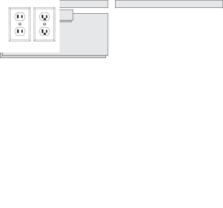
Grounded Tools:
Tools with Three Prong Plugs
Tools marked “Grounding Required” have a three wire cord and three prong grounding plug. The plug must be connected to a properly grounded outlet (See Figure A). If the tool should electrically malfunction or break down, grounding provides a low resistance path to carry electricity away from the user, reducing the risk of electric shock.
The grounding prong in the plug is connected through the green wire inside the cord to the grounding system in the tool. The green wire in the cord must be the only wire connected to the tool's grounding system and must never be attached to an electrically “live” terminal.
Your tool must be plugged into an appropriate outlet, properly installed and grounded in accordance with all codes and ordinances. The plug and outlet should look like those in Figure A.
Double Insulated Tools: Tools with Two Prong Plugs
Tools marked “Double Insulated” do not require grounding. They have special double insulation system which satisfies OSHA requirements and complies with the applicable standards of Underwriters Laboratories, Inc., the Canadian Standard Association and the National Electrical Code. Double Insulated tools may be used in either of the 120 volt outlets shown in Figures B and C.
EXTENSION CORDS
Grounded tools require a three wire extension cord. Double insulated tools can use either a two or three wire extension cord. As the distance from the supply outlet increases, you must use a heavier gauge extension cord. Using extension cords with inadequately sized wire causes a serious drop in voltage, resulting in loss of power and possible tool damage. Refer to the table shown to determine the required minimum wire size.
The smaller the gauge number of the wire, the greater the capacity of the cord. For example, a 14 gauge cord can carry a higher current than a 16 gauge cord. When using more than one extension cord to make up the total length, be sure each cord contains at least the minimum wire size required. If you are using one extension cord for more than one tool, add the nameplate amperes and use the sum to determine the required minimum wire size.
Guidelines for Using Extension Cords
•If you are using an extension cord outdoors, be sure it is marked with the suffix “W-A” (“W” in Canada) to indicate that it is acceptable for outdoor use.
•Be sure your extension cord is properly wired and in good electrical condition. Always replace a damaged extension cord or have it repaired by a qualified person before using it.
•Protect your extension cords from sharp objects, excessive heat and damp or wet areas.
Recommended Minimum Wire Gauge
for Extension Cords*
Nameplate |
|
Extension Cord Length |
|
|||||
|
|
|
|
|
|
|
||
Amperes |
25' |
50' |
75' |
100' |
150' |
|
200' |
|
0 - 5 |
16 |
16 |
16 |
14 |
12 |
|
12 |
|
5.1 |
- 8 |
16 |
16 |
14 |
12 |
10 |
|
-- |
8.1 - 12 |
14 |
14 |
12 |
10 |
-- |
|
-- |
|
12.1 |
- 15 |
12 |
12 |
10 |
10 |
-- |
|
-- |
15.1 |
- 20 |
10 |
10 |
10 |
-- |
-- |
|
-- |
|
|
|
|
|
|
|
|
|
* Based on limiting the line voltage drop to five volts at 150% of the rated amperes.
READ AND SAVE ALL INSTRUCTIONS
FOR FUTURE USE.
page 5
TOOL ASSEMBLY
WARNING
To reduce the risk of injury, always unplug tool before attaching or removing accessories or making adjustments. Use only specifically recommended accessories. Others may be hazardous.
Adjusting the Spade Side Handle (Cat. No. 5337-20, 5339-20 only)
The spade side handle is provided on demolition hammers only. Do not use the spade side handle on Rotary Hammers.
1.Slightly loosen the spade side handle by turning the spade side handle adjusting knob counterclockwise.
2.Rotate the spade side handle to the desired position. The handle can be moved to the left or right of the tool, as well as forward or backward.
3.Securely tighten the spade side handle adjusting knob.
Adjusting the Straight Side Handle
Screw the straight side handle into one of three positions (top, left side, or right side). Tighten securely.
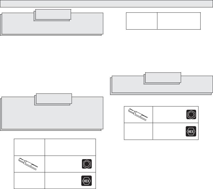
SDS Max shank Cat. No. 5339-20,
5342-20
1.Clean and grease the bit or chisel shank.
2.Insert the bit or chisel into the nose of the tool.
3.Rotate the bit or chisel slowly until it aligns with the locking mechanism.
4.Push the bit or chisel into the tool until it locks (Fig. 2).
5.Pull on the bit or chisel to verify that it is locked into place.
6.To remove, pull the bit release collar toward the rear of the tool and remove the bit or chisel.
WARNING
To reduce the risk of injury, use only specifically recommended MILWAUKEE hammer chisels. Others may damage tool.
WARNING
To reduce the risk of injury when hammering with rotation, always use the straight side handle when using this tool. Always brace or hold securely.
To reduce the risk of injury when hammering with or without rotation, wear safety goggles or glasses with side shields.
Installing Bits and Chisels
Spline shank
Cat. No. 5340-20 only
Round hex shank
Cat. No. 5340-20 only
Hex shank
Cat. No. 5337-20 only
NOTE: To reduce the risk of damage to the bit lock, do not use round hex shank bits in the 5337-20. Only use hex shank bits in this tool.
1.Clean and grease the bit or chisel shank.
2.Pull out the bit lock and rotate it 180°.
3.Insert the bit or chisel into the nose of the tool (Fig. 1)
NOTE: When using hex (on cat. no. 5337-20) or hex/round (on cat. no. 5340-20) bits or chisels, the notch in the shank must face toward the bottom of the nosepiece of the tool.
4.Lock the bit or chisel by pulling out the bit lock and rotating it 180°.
5.Pull on the bit or chisel to verify that it is locked into place.
6.To remove, rotate the bit lock 180° and remove the bit or chisel.
NOTE: Use caution when handling hot bits and chisels.
Installing Hammer Chisels
Round hex shank (Cat. No. 5340-20)
Hex shank
(Cat. No. 5337-20)
Always clean and grease the chisel shank before inserting the chisel into the tool. Inspect the shank to make sure it is not "mushroomed", as described in "Maintaining Hammer Chisels". Always make sure that the chisel is in good working condition before use.
page 6
OPERATION
Electronic Feedback Control Circuit
These hammers have an Electronic Feedback Control Circuit (EFCC) which helps improve the operation and life of the tool.
Feedback Control
The electronic speed control circuit allows the tool to maintain constant speed and torque between no-load and load conditions.
Soft Start
The Soft-Start feature reduces the amount of torque reaction to the tool and the user. This feature gradually increases the motor speed up from zero to the speed set by the speed control dial.
WARNING
To reduce the risk of injury, wear safety goggles or glasses with side shields. Unplug the tool before changing accessories or making adjustments.
Selecting Speed
The speed control dial on these hammers allows the user to adjust the rotating speed (RPM) and the impact rate (BPM) of the tool.
To change the speed, set the speed control dial to the desired setting.
•Lower speeds provide more control when starting holes and reduce 'spalling' on breakthrough. Spalling occurs when pieces of material chip off around the drilled hole on breakthrough. When chiseling in soft or brittle materials, use lower speeds to reduce damage to surrounding areas of the material.
•Higher speeds provide faster penetration when drilling and chiseling in demolition work.
Selecting Action Cat. No. 5337-20
The cat. no. 5337-20 demolition hammer is for "hammering-only". No rotation is available. Only chisels and other "hammering-only" accessories should be used.
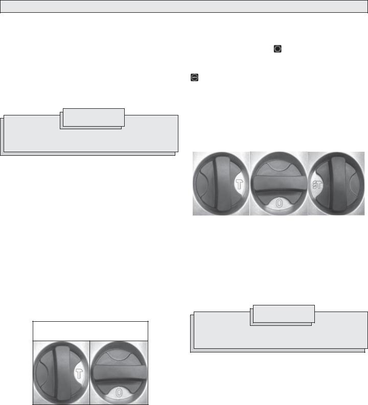
Cat. No. 5339-20  (Fig. 3)
The cat. no. 5339-20 demolition hammer is for "hammering-only". No rotation is available. The action selector is used to select the action:
Fig. 3 |
|
Hammering Only |
Chisel Adjustment |
1.Hammering only.  For use with "hammering only" accessories. Use this setting for chiseling.
2.Chisel adjustment.  Use this setting to adjust the angle of the chisel blade in relation to the tool. With a chisel mounted in the tool, twist the chisel to the desired angle. Then, rotate the action selector to the "hammering only" setting for use.
NOTE: To engage the hammering mechanism, maintain pressure on the bit/chisel. When pressure is released, hammering stops.
Cat. No. 5340-20 

The cat. no. 5340-20 rotary hammer has "hammering-only" and "hammering with rotation", depending on the type of shank inserted into the tool.
For "hammering-only": Insert a chisel or other "hammering-only" accessory with a 3/4" Hex with 21/32" Round shank into the nose of the tool (see "Inserting Bits and Chisels"). The rotational drive mechanism will run but not engage with the chisel, resulting in "hammering-only" action.
For "hammering with rotation": Insert a drill or coring bit with a spline shank into the nose of the tool (see "Inserting Bits and Chisels"). The rotational drive mechanism engages with the bit, resulting in "hammering
with rotation" action.
Cat. No. 5342-20  (Fig. 4)
Cat. no. 5342-20 rotary hammer has "hammering-only", "hammering with rotation", and "chisel adjustment" settings. The action selector is used to select the action:
Fig. 4 |
|
Hammering with |
|
Hammering Only |
Chisel Adjustment |
||
Rotation |
|||
|
|
|
|
|
|
|
1.Hammering only. For use with "hammering only" accessories. Use this setting for chiseling.
2.Hammering with rotation.  Use this setting for drilling holes with drill bits. Do not use "hammering with rotation" when using chisels or other "hammering-only" accessories.
3.Chisel adjustment.  Use this setting to adjust the angle of the chisel blade in relation to the tool. With a chisel mounted in the tool, twist the chisel to the desired angle. Then, rotate the action selector to the Hammering only setting for use.
NOTE: To engage the hammering mechanism, maintain pressure on the bit/chisel. When pressure is released, hammering stops.
WARNING
To reduce the risk of injury, when using chisels or other hammer- ing-only accessories in cat. no. 5342-20, the action selector must be set to the "hammering only" position.
Starting and Stopping the Tool
1.To start the tool, pull the trigger.
2.To stop the tool, release the trigger.
Locking the Trigger (Cat. No. 5337-20, 5339-20 only)
The lock button on the demolition hammers holds the trigger in the "On" position for continuous use.
1.To lock the trigger, hold in the lock button while pulling the trigger. Release the trigger.
2.To unlock the trigger, pull the trigger and release. The lock button will pop out.
page 7
Cold Hammering
If the hammer is stored for a long period of time or at cold temperatures, the lubrication may become stiff and the tool may not hammer initially or the hammering may be weak. If this happens:
1.Insert a chisel into the tool.
2.Pull the trigger and apply the chisel against a scrap piece of concrete.
3.Turn the tool On and Off every few seconds. After 15 seconds to 2 minutes, the tool will start hammering normally. The colder the hammer is, the longer it will take to warm up.
Operator Force
These hammers feature the Vibration Isolation System to provide the operator with comfort without sacrificing power or performance. The motor housing is suspended independently from the switch handle. Insulating elements absorb vibration when hammering and drilling.
Ideal operator force compresses the handle slightly and allows the tool to work aggressively while the handle provides maximum vibration dampening.
Excessive operator force compresses the handle too far and reduces the vibration dampening. Users will be able to feel the difference and should adjust the force to the handle accordingly.
WARNING
Applying greater pressure does not increase the tool's effectiveness. If the applied working pressure is too high, the shock absorber will be pushed together making vibration to the handle noticeably stronger.
Hammering Only
1.Insert a chisel or other "hammering only" accessory into the tool (see "Installing Bits and Chisels").
2.Position the tool on the workpiece.
3.Grasp both handles firmly (trigger handle and either the spade handle or straight handle).
4.Pull the trigger. Always hold the tool securely using two handles and maintain control.
5.Use only enough pressure to hold the tool in place, engage the hammering mechanism, and prevent the tip of the chisel from wandering. This tool has been designed to achieve top performance with only moderate pressure. Let the tool do the work.
NOTE: To engage the hammering mechanism, maintain pressure on the bit/chisel. When pressure is released, hammering stops.
6.When chiseling or chipping, hold the tool at an angle to the work area.
For best performance, work from a corner or close the edge of the work and break off a small area at a time.
If a hammer iron gets stuck:
1.Unplug the tool.
2.Pull out bit lock and rotate it 180°.
3.Pull the tool off of the stuck accessory.
4.Remove the accessory from the workpiece.
Hammering with Rotation
1.Insert a drill or coring bit into the tool (see "Installing Bits and Chisels").
2.Position the tool on the workpiece.
3.Grasp both handles firmly (trigger handle and straight handle).
WARNING
To reduce the risk of injury, hold or brace securely. Always be prepared for drill reaction when bit binds, when hole becomes clogged, when striking embedded materials, and during hole breakthrough.
4.Pull the trigger. Always hold the tool securely using the straight handle and trigger handle and maintain control.
5.Use only enough pressure to hold the tool in place, engage the hammering mechanism, and prevent the tip of the bit from wandering. This tool has been designed to achieve top performance with only moderate pressure. Let the tool do the work.
When pressure is released, hammering stops.
6.When drilling deep holes, the speed may begin to drop off. Pull the bit partially out of the hole while the tool is running to help clear dust.
NOTE: Do not use water to settle the dust since it will clog the bit flutes and tend to make the bit bind in the hole.
If a bit binds:
If the bit should bind, a built in, nonadjustable slip clutch prevents the bit from turning when the tool is held or braced securely. If this occurs
1.Turn off and unplug the tool.
2.Free the bit from the workpiece.
3.Clear debris from the hole.
4.Begin drilling again.
WARNING
Use MILWAUKEE core bits Cat. No. 48-20-5125 through 48-20-5165. Do not use LHS (Large Hole System) Components with rotary hammers 5340-20 and 5342-20. The bits could fail, breaking apart at the threaded stud and causing injury and property damage.
Using Rotary Percussion Core Bits (Fig. 5 - 7)
Core bits are useful for drilling larger holes for conduit and pipe. MILWAUKEE Heavy-Duty Core Bits have heat-treated steel bodies with durable carbide tips. These core bits are specially designed for fast, accurate drilling with combined hammering and rotary action.
1.Clean and lubricate the threads on the adapter and core bit to make later removal easier. Screw the threaded end of the adapter into the rear of the core bit.
2.Push the guide plate onto the pointed end of the center pin. Insert the center pin and guide plate assembly into the core bit. Be sure the small end of the center pin is securely placed into the hole in the center of the core bit (Fig. 5).
Fig. 5
3.Insert the adapter into the nose of the tool (see “Installing Bits and Chisels”. Set the action selector to the hammering-with-rotation setting.
page 8

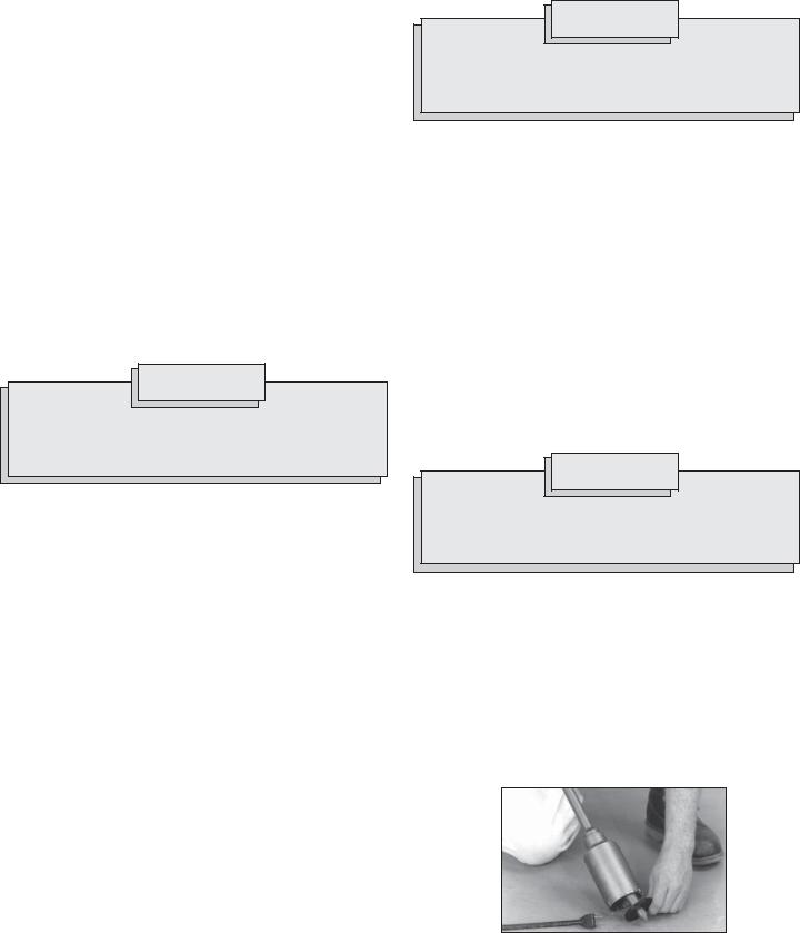
4.Press the center pin firmly against your center mark, hold the tool firmly and pull the trigger (Fig. 6).
Fig. 6
NOTE: If a center pin and guide plate are not available, use a template or notched board to start the hole (Fig. 7).
Fig. 7
5.After drilling to about the depth of the core bit teeth, remove the center pin and guide plate from the core bit. Resume drilling.
6.To change the core bit, hold the tool upwards, pointing it away from your body, and run the tool allowing rotation and impacting for about five seconds to loosen the core bit from the adapter shank.
NOTE: To make deeper holes, remove the core bit, break and remove the core. Resume drilling. When drilling long or deep holes, after each inch of penetration pull the bit partially out of the hole while the tool is running, to help clear dust from the bit flutes. Dust can clog the bit flutes and can make the bit bind in the hole. If this occurs, stop the tool, free the bit and begin again.
Drilling Large Diameter Holes with Core Bits (Fig. 8-13)
When drilling holes with large diameter core bits, dust may build up in the cut and can cause the tool to stall, bind, or cut slowly. By creating an opening for the dust to escape, drilling time, bit stress, and tool stress can be reduced.
1.Start the cut as normal.
2.Once the bit is firmly established in the cut (about 1/4" deep), remove the bit from the cut (Fig. 8).
Fig. 8
Cut approximately 1/4" deep with a core bit.
3.Remove the bit from the tool.
4.Install a standard fluted bit, approximately 7/8" in diameter, onto the tool.
5.Drill a perpendicular hole through the kerf of the large hole (Fig. 9).
•Depending on the location of the work, the hole should either break through the other side of the hole/floor or extend 4"-5" past the end of the workpiece (such as into the dirt below a concrete slab).
•If dust builds up in the hole, vacuum it out and continue drilling.
•If drilling through a wall, the hole for dust should be drilled on the lowest part of the large hole kerf (Fig. 9) as the dust will fall there when drilling and can be evacuated more easily.
Fig. 9
Drill a hole through the work.
6.Reinstall the core bit and continue drilling (Fig. 10 & 11). Dust and debris will fall through the hole and optimize the cutting ability of the bit.
Fig. 10
Dust and debris will fall through the hole.
Top view
Fig. 11
Side view of slab
page 9

7.For core bits, once the maximum core bit depth is drilled, the core must be broken and removed.
•Install a chisel bit.
•Place the chisel into the hole kerf (Fig. 12).
•Chisel down into the kerf at several points until the core is loose or broken.
• Remove the core and vacuum/remove any remaining dust and debris.
• Install the core bit and continue the cut.
F i g .
NOTE: If unable to drill a hole in the kerf, pull back on the bit with the hammer running (Fig. 13). This will remove some of the dust and debris from the cut. Repeat this for every inch of drilling. If necessary, vacuum dust and debris from the cut and surrounding area.
Fig. 13 |
Pull bit out as far |
|
as possible once |
|
or twice per inch |
|
drilled. |
|
|
Chiseling and Chipping
These MILWAUKEE Hammers may be used for chipping and chiseling.
When chiseling, hold the tool at an angle to the workpiece. Work from a corner or close to the edge of the workpiece, breaking off one small area at a time rather than attempting too large an area.
A variety of accessories are available.
Bushing Tools
Used to surface concrete.
Mortar Cutting Chisels (Seam Tools)
For removing old mortar for tuck pointing or caulking.
Bull Points
For demolition work and starting holes in concrete slabs.
Flat Chisels
For edging, chipping or channeling.
Scaling Chisels
For removing weld spatter or scale and cutting straight lines.
Slotting Chisel
For slotting and cutting between drilled holes in concrete and masonry.
page 10
 Loading...