


TM-353E January 2001
Eff. w/Serial Number JJ339876
Processes
TIG (GTAW) Welding
Stick (SMAW) Welding
Description
Arc Welding Power Source
SyncrowaveR 250
60 Hz, 50 Hz
Visit our website at
www.MillerWelds.com

TABLE OF CONTENTS
1. Safety Precautions – Read Before Using . . . . . . . . . . . . . . . . . . . . . . . . . . . . . . . . . . . . . . . . . . . . . . |
1 |
|
1.1 |
Symbol Usage . . . . . . . . . . . . . . . . . . . . . . . . . . . . . . . . . . . . . . . . . . . . . . . . . . . . . . . . . . . . . . . . |
1 |
1.2 |
Servicing Hazards . . . . . . . . . . . . . . . . . . . . . . . . . . . . . . . . . . . . . . . . . . . . . . . . . . . . . . . . . . . . . |
1 |
1.3 |
EMF Information . . . . . . . . . . . . . . . . . . . . . . . . . . . . . . . . . . . . . . . . . . . . . . . . . . . . . . . . . . . . . . . |
2 |
SECTION 2 – DEFINITIONS . . . . . . . . . . . . . . . . . . . . . . . . . . . . . . . . . . . . . . . . . . . . . . . . . . . . . . . . . . . . |
3 |
|
2-1. |
Warning Label Definitions . . . . . . . . . . . . . . . . . . . . . . . . . . . . . . . . . . . . . . . . . . . . . . . . . . . . . . . |
3 |
2-2. Rating Label For CE Products . . . . . . . . . . . . . . . . . . . . . . . . . . . . . . . . . . . . . . . . . . . . . . . . . . . |
4 |
|
2-3. |
Symbols And Definitions . . . . . . . . . . . . . . . . . . . . . . . . . . . . . . . . . . . . . . . . . . . . . . . . . . . . . . . . |
5 |
SECTION 3 – INSTALLATION . . . . . . . . . . . . . . . . . . . . . . . . . . . . . . . . . . . . . . . . . . . . . . . . . . . . . . . . . . . |
6 |
|
3-1. |
Specifications . . . . . . . . . . . . . . . . . . . . . . . . . . . . . . . . . . . . . . . . . . . . . . . . . . . . . . . . . . . . . . . . . |
6 |
3-2. Volt-Ampere Curves . . . . . . . . . . . . . . . . . . . . . . . . . . . . . . . . . . . . . . . . . . . . . . . . . . . . . . . . . . . . |
6 |
|
3-3. Duty Cycle And Overheating . . . . . . . . . . . . . . . . . . . . . . . . . . . . . . . . . . . . . . . . . . . . . . . . . . . . . |
7 |
|
3-4. |
Selecting A Location . . . . . . . . . . . . . . . . . . . . . . . . . . . . . . . . . . . . . . . . . . . . . . . . . . . . . . . . . . . . |
8 |
3-5. |
Dimensions And Weights . . . . . . . . . . . . . . . . . . . . . . . . . . . . . . . . . . . . . . . . . . . . . . . . . . . . . . . . |
8 |
3-6. |
Tipping . . . . . . . . . . . . . . . . . . . . . . . . . . . . . . . . . . . . . . . . . . . . . . . . . . . . . . . . . . . . . . . . . . . . . . . |
9 |
3-7. |
Weld Output Terminals And Selecting Cable Sizes . . . . . . . . . . . . . . . . . . . . . . . . . . . . . . . . . . . |
9 |
3-8. |
Remote 14 Receptacle . . . . . . . . . . . . . . . . . . . . . . . . . . . . . . . . . . . . . . . . . . . . . . . . . . . . . . . . . |
10 |
3-9. 115 Volts AC Duplex Receptacle And Shielding Gas Connections . . . . . . . . . . . . . . . . . . . . . . |
10 |
|
3-10.Electrical Service Guide . . . . . . . . . . . . . . . . . . . . . . . . . . . . . . . . . . . . . . . . . . . . . . . . . . . . . . . . . |
11 |
|
3-11.Placing Jumper Links And Connecting Input Power . . . . . . . . . . . . . . . . . . . . . . . . . . . . . . . . . . |
12 |
|
SECTION 4 – OPERATION . . . . . . . . . . . . . . . . . . . . . . . . . . . . . . . . . . . . . . . . . . . . . . . . . . . . . . . . . . . . . |
13 |
|
4-1. |
Controls . . . . . . . . . . . . . . . . . . . . . . . . . . . . . . . . . . . . . . . . . . . . . . . . . . . . . . . . . . . . . . . . . . . . . . |
13 |
4-2. |
Output Selector Switch . . . . . . . . . . . . . . . . . . . . . . . . . . . . . . . . . . . . . . . . . . . . . . . . . . . . . . . . . |
14 |
4-3. |
Meters . . . . . . . . . . . . . . . . . . . . . . . . . . . . . . . . . . . . . . . . . . . . . . . . . . . . . . . . . . . . . . . . . . . . . . . |
14 |
4-4. |
Crater Time Controls . . . . . . . . . . . . . . . . . . . . . . . . . . . . . . . . . . . . . . . . . . . . . . . . . . . . . . . . . . . |
15 |
4-5. |
Spot Time Controls . . . . . . . . . . . . . . . . . . . . . . . . . . . . . . . . . . . . . . . . . . . . . . . . . . . . . . . . . . . . . |
15 |
4-6. AC Balance Control . . . . . . . . . . . . . . . . . . . . . . . . . . . . . . . . . . . . . . . . . . . . . . . . . . . . . . . . . . . . |
16 |
|
4-7. |
Amperage Adjustment Controls . . . . . . . . . . . . . . . . . . . . . . . . . . . . . . . . . . . . . . . . . . . . . . . . . . |
17 |
4-8. |
Output (Contactor) Control Switch . . . . . . . . . . . . . . . . . . . . . . . . . . . . . . . . . . . . . . . . . . . . . . . . |
17 |
4-9. |
Arc Controls . . . . . . . . . . . . . . . . . . . . . . . . . . . . . . . . . . . . . . . . . . . . . . . . . . . . . . . . . . . . . . . . . . |
18 |
4-10.Postflow Time Control . . . . . . . . . . . . . . . . . . . . . . . . . . . . . . . . . . . . . . . . . . . . . . . . . . . . . . . . . . |
18 |
|
4-11.High Frequency Controls . . . . . . . . . . . . . . . . . . . . . . . . . . . . . . . . . . . . . . . . . . . . . . . . . . . . . . . . |
19 |
|
4-12.Preflow Time Control (Optional) . . . . . . . . . . . . . . . . . . . . . . . . . . . . . . . . . . . . . . . . . . . . . . . . . . |
19 |
|
SECTION 5 – THEORY OF OPERATION . . . . . . . . . . . . . . . . . . . . . . . . . . . . . . . . . . . . . . . . . . . . . . . . . |
20 |
|
SECTION 6 – TROUBLESHOOTING . . . . . . . . . . . . . . . . . . . . . . . . . . . . . . . . . . . . . . . . . . . . . . . . . . . . . |
22 |
|
6-1. |
Troubleshooting Table . . . . . . . . . . . . . . . . . . . . . . . . . . . . . . . . . . . . . . . . . . . . . . . . . . . . . . . . . . |
22 |
6-2. |
Troubleshooting Circuit Diagram For Welding Power Source . . . . . . . . . . . . . . . . . . . . . . . . . . |
26 |
6-3. Waveforms For Section 6-2 . . . . . . . . . . . . . . . . . . . . . . . . . . . . . . . . . . . . . . . . . . . . . . . . . . . . . . |
28 |
|
6-4. |
Control Board PC1 Testing Information (Use With Section 6-5) . . . . . . . . . . . . . . . . . . . . . . . . |
30 |
6-5. |
Control Board PC1 Test Point Values . . . . . . . . . . . . . . . . . . . . . . . . . . . . . . . . . . . . . . . . . . . . . . |
31 |
6-6. |
Remote Board PC2 Testing Information (Use With Section 6-7) . . . . . . . . . . . . . . . . . . . . . . . . |
33 |
6-7. |
Remote 14 Filter Board PC2 Test Point Values (Use With Section 6-2 And Section 6-6) . . . . |
34 |
6-8. |
Meter Calibration . . . . . . . . . . . . . . . . . . . . . . . . . . . . . . . . . . . . . . . . . . . . . . . . . . . . . . . . . . . . . . |
35 |
6-9. |
Input Voltage Labels And Connections . . . . . . . . . . . . . . . . . . . . . . . . . . . . . . . . . . . . . . . . . . . . . |
36 |
SECTION 7 – MAINTENANCE . . . . . . . . . . . . . . . . . . . . . . . . . . . . . . . . . . . . . . . . . . . . . . . . . . . . . . . . . . |
37 |
|
7-1. |
Routine Maintenance . . . . . . . . . . . . . . . . . . . . . . . . . . . . . . . . . . . . . . . . . . . . . . . . . . . . . . . . . . . |
37 |
7-2. |
Circuit Breaker CB1 . . . . . . . . . . . . . . . . . . . . . . . . . . . . . . . . . . . . . . . . . . . . . . . . . . . . . . . . . . . . |
37 |
7-3. Fuses F1 And F2 . . . . . . . . . . . . . . . . . . . . . . . . . . . . . . . . . . . . . . . . . . . . . . . . . . . . . . . . . . . . . . |
38 |
|
7-4. Adjusting Spark Gaps . . . . . . . . . . . . . . . . . . . . . . . . . . . . . . . . . . . . . . . . . . . . . . . . . . . . . . . . . . |
38 |
|
SECTION 8 – HIGH FREQUENCY (HF) . . . . . . . . . . . . . . . . . . . . . . . . . . . . . . . . . . . . . . . . . . . . . . . . . . . |
39 |
|
8-1. Welding Processes Using HF . . . . . . . . . . . . . . . . . . . . . . . . . . . . . . . . . . . . . . . . . . . . . . . . . . . . |
39 |
|
8-2. |
Sources Of HF Radiation From Incorrect Installation . . . . . . . . . . . . . . . . . . . . . . . . . . . . . . . . . |
39 |
8-3. |
Correct Installation . . . . . . . . . . . . . . . . . . . . . . . . . . . . . . . . . . . . . . . . . . . . . . . . . . . . . . . . . . . . . |
40 |
SECTION 9 – ELECTRICAL DIAGRAMS . . . . . . . . . . . . . . . . . . . . . . . . . . . . . . . . . . . . . . . . . . . . . . . . . |
41 |
|
SECTION 10 – PARTS LIST . . . . . . . . . . . . . . . . . . . . . . . . . . . . . . . . . . . . . . . . . . . . . . . . . . . . . . . . . . . . |
68 |
|
TM-353D

Declaration of Conformity For
European Community (CE) Products
NOTE
This information is provided for units with CE certification (see rating label on unit.)
Manufacturer’s Name:
Manufacturer’s Address:
Declares that the product:
Miller Electric Mfg. Co.
1635 W. Spencer Street
Appleton, WI 54914 USA
Syncrowave 250
conforms to the following Directives and Standards:
Directives
Low Voltage Directive: 73/23/EEC
Machinery Directives: 89/392/EEC, 91/368/EEC, 93/C 133/04, 93/68/EEC
Electromagnetic Capability Directives: 89/336, 92/31/EEC
Standards
Safety Requirements for Arc Welding Equipment part 1: EN 60974-1: 1990
Arc Welding Equipment Part 1: Welding Power Sources: IEC 974-1 (April 1995 – Draft revision)
Degrees of Protection provided by Enclosures (IP code): IEC 529: 1989
Insulation coordination for equipment within low-voltage systems:
Part 1: Principles, requirements and tests: IEC 664-1: 1992
Electromagnetic compatibility (EMC) Product standard for arc welding equipment: EN50199: August 1995
European Contact: Mr. Luigi Vacchini, Managing Director
MILLER Europe S.P.A.
Via Privata Iseo
20098 San Giuliano
Milanese, Italy
Telephone: 39(02)98290-1
Fax: 39(02)98281-552
dec_con1 10/95
SECTION 1 – SAFETY PRECAUTIONS FOR SERVICING
safety_stm1 4/95
1-1. Symbol Usage
Means Warning! Watch Out! There are possible hazards with this procedure! The possible hazards are shown in the adjoining symbols.
Y Marks a special safety message.
. Means NOTE; not safety related.
This group of symbols means Warning! Watch Out! possible ELECTRIC SHOCK, MOVING PARTS, and HOT PARTS hazards. Consult symbols and related instructions below for necessary actions to avoid the hazards.
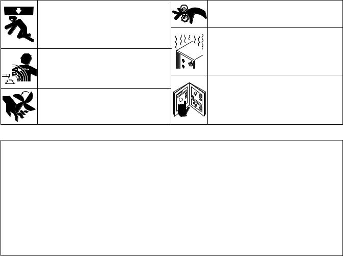
1-2. Servicing Hazards
WARNING |
The symbols shown below are used throughout this manual to call attention to and identify possible hazards. When you see the symbol, watch out, and follow the related instructions to avoid the hazard.
Only qualified persons should service, test, maintain, and repair this unit.
During servicing, keep everybody, especially children, away.
ELECTRIC SHOCK can kill.
1.Do not touch live electrical parts.
2.Stop engine or turn OFF welding power source and wire feeder, and disconnect and lockout input power using line disconnect switch, circuit breakers, or by removing plug from receptacle before servicing unless the procedure specifically requires an energized unit.
3.Insulate yourself from ground by standing or
working on dry insulating mats big enough to prevent contact with the ground.
4.Do not leave live unit unattended.
5.When testing a live unit, use the one-hand method.
Do not put both hands inside unit. Keep one hand free.
6.Disconnect input power conductors from
deenergized supply line BEFORE moving a welding power source.
SIGNIFICANT DC VOLTAGE exists after removal of input power on inverters.
7.Turn Off inverter, disconnect input power, and discharge input capacitors according to instructions in Maintenance Section before touching any parts.
STATIC ELECTRICITY can damage parts on circuit boards.
1.Put on grounded wrist strap BEFORE handling boards or parts.
2.Use proper static-proof bags to store, move, or ship PC boards.
FIRE OR EXPLOSION can result from placing unit on, over, or near combustible surfaces.
1. Do not place unit on, over, or near combustible surfaces.
2. Do not service unit near flammables.
FLYING PIECES OF METAL or DIRT can injure eyes.
1.Wear safety glasses with side shields or face shield during servicing.
2.Be careful not to short metal tools, parts, or wires together during testing and servicing.
HOT PARTS can cause severe burns.
1.Do not touch hot parts bare handed.
2.Allow cooling period before servicing welding gun or torch.
EXPLODING PARTS can cause injury.
1.Failed parts can explode or cause other parts to explode when power is applied to inverters.
2.Always wear a face shield and long sleeves when servicing inverters.
ELECTRIC SHOCK HAZARD from incorrect use of test equipment.
1.Turn Off welding power source and wire feeder or stop engine before making or changing meter lead connections.
2.At least one meter lead should be a self-retaining spring clip such as an alligator clamp.
3.Read instructions for test equipment.
HIGH-FREQUENCY RADIATION can interfere with radio navigation, safety services, computers, and communications equipment.
1.Have only qualified persons familiar with electronic equipment perform this installation.
2.The user is responsible for having a qualified electrician promptly correct any interference problem resulting from the installation.
3.If notified by the FCC about interference, stop using the equipment at once.
4.Have the installation regularly checked and maintained.
5.Keep high-frequency source doors and panels tightly shut, keep spark gaps at correct setting, and use grounding and shielding to minimize the possibility of interference.
Syncrowave 250 |
TM-353 Page 1 |
FALLING EQUIPMENT can cause serious personal injury and equipment damage.
1.Use lifting eye to lift unit only, NOT running gear, gas cylinders, or any other accessories.
2.Use equipment of adequate capacity to lift unit.
MAGNETIC FIELDS FROM HIGH CURRENTS can affect pacemaker operation.
1.Pacemaker wearers keep away from servicing areas until consulting your doctor.
MOVING PARTS can cause injury.
1.Keep away from moving parts such as fans.
2.Keep all doors, panels, covers, and guards closed and securely in place.
MOVING PARTS can cause injury.
1.Keep away from moving parts.
2.Keep away from pinch points such as drive rolls.
OVERUSE can cause OVERHEATED EQUIPMENT.
1.Allow cooling period.
2.Reduce current or reduce duty cycle before starting to weld again.
3.Follow rated duty cycle.
READ INSTRUCTIONS.
1.Use MILLER Testing Booklet (Part No. 150 853) when servicing this unit.
2.Consult the Owner’s Manual for welding safety precautions.
3.Use only genuine MILLER replacement parts.
1-3. EMF Information
Considerations About Welding And The Effects Of Low Frequency Electric And Magnetic Fields
The following is a quotation from the General Conclusions Section of the U.S. Congress, Office of Technology Assessment, Biological
Effects of Power Frequency Electric & Magnetic Fields – Background Paper, OTA-BP-E-53 (Washington, DC: U.S. Government Printing Office, May 1989): “. . . there is now a very large volume of scientific findings based on experiments at the cellular level and from studies with animals and people which clearly establish that low frequency magnetic fields can interact with, and produce changes in, biological systems. While most of this work is of very high quality, the results are complex. Current scientific understanding does not yet allow us to interpret the evidence in a single coherent framework. Even more frustrating, it does not yet allow us to draw definite conclusions about questions of possible risk or to offer clear science-based advice on strategies to minimize or avoid potential risks.”
To reduce magnetic fields in the workplace, use the following procedures:
1.Keep cables close together by twisting or taping them.
2.Arrange cables to one side and away from the operator.
3.Do not coil or drape cables around the body.
4.Keep welding power source and cables as far away as practical.
5.Connect work clamp to workpiece as close to the weld as possible.
About Pacemakers:
The above procedures are also recommended for pacemaker wearers. Consult your doctor for complete information.
TM-353 Page 2 |
Syncrowave 250 |

SECTION 2 – DEFINITIONS
2-1. Warning Label Definitions
1 |
1.1 |
|
1.2 |
1.3 |
2 |
2.1 |
2.2 |
|
2.3 |
3 |
3.1 |
|
3.2 |
3.3 |
4 |
4.1 |
|
|
|
|
|
+ |
+ |
+ |
5 |
+ |
|
|
6 |
|
|
|
|
|
|
|
|
|
S-176 254-A |
Warning! Watch Out! There are possible hazards as shown by the symbols.
1Electric shock from welding electrode or wiring can kill.
1.1Wear dry insulating gloves. Do not touch electrode with bare hand. Do not wear wet or damaged gloves.
1.2Protect yourself from electric shock by insulating yourself from work and ground.
1.3Disconnect input plug or power before working on machine.
2Breathing welding fumes can be hazardous to your health.
2.1Keep your head out of the fumes.
2.2Use forced ventilation or local exhaust to remove the fumes.
2.3Use ventilating fan to remove fumes.
3Welding sparks can cause explosion or fire.
3.1Keep flammables away from welding. Don’t weld near flammables.
3.2Welding sparks can cause fires. Have a fire extinguisher nearby and have a watch person ready to use it.
3.3Do not weld on drums or any closed containers.
4Arc rays can burn eyes and injure skin.
4.1Wear hat and safety glasses. Use ear protection and button shirt collar. Use welding helmet with correct shade of filter. Wear complete body protection.
5Become trained and read the instructions before working on the machine or welding.
6Do not remove or paint over (cover) the label.
Syncrowave 250 |
TM-353 Page 3 |

2-2. Rating Label For CE Products
|
|
|
|
|
|
|
|
|
|
1 |
1 |
ISO/IEC 974-1 |
|
|
|||
|
|
|
|
|
||||
|
|
7A/10.2V |
310A/22.4V |
|
|
|||
|
|
X |
25% |
60% |
100% |
|
|
|
|
|
I2 |
310A |
200A |
155A |
|
|
|
|
|
U0 = 80V |
|
|
|
|
|
|
|
|
U2 |
22.4V |
18V |
16.2V |
|
|
|
|
|
5A/20.2V |
310A/32.4V |
|
|
|||
|
|
X |
25% |
60% |
100% |
|
|
|
|
|
I2 |
310A |
200A |
155A |
|
|
|
|
|
U0 = 80V |
|
|
|
|
|
|
|
|
U2 |
32.4V |
28V |
26.2V |
|
|
|
|
1 |
U1 = 220 I1max = 117.2A |
I1Eff = 59A |
|
|
|||
|
50 Hz |
|
|
|
|
|
|
|
|
|
U1 = 380 I1max = 72.2A |
I1Eff = 36A |
|
|
|||
|
|
U1 = 415 I1max = 63.8A |
I1Eff = 32A |
|
|
|||
|
|
IP 21S |
|
|
|
|
|
|
|
|
|
|
|
|
S-178 813-A |
|
|
|
|
|
|
|
|
|
|
|
|
|
|
|
|
|
|
|
|
TM-353 Page 4 |
Syncrowave 250 |
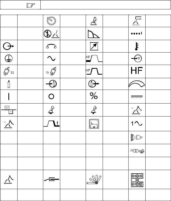
2-3. Symbols And Definitions
NOTE
Some symbols are found only on CE products.
A |
Amperes |
|
Panel–Local |
|
Gas Tungsten Arc |
|
|
Shielded Metal Arc |
|
|
|
|
|
|
|||||
|
|
|
Welding (GTAW) |
|
|
Welding (SMAW) |
|||
|
|
|
|
|
|
|
|||
V |
Volts |
|
Do Not Switch |
|
Arc Force (DIG) |
|
|
Spot Timer |
|
|
While Welding |
|
|
|
|||||
|
|
|
|
|
|
|
|||
|
Output |
|
Circuit Breaker |
|
Remote |
|
|
Temperature |
|
|
Protective Earth |
|
Alternating Current |
|
High Frequency - |
|
|
Input |
|
|
(Ground) |
|
|
Start |
|
|
|||
|
|
|
|
|
|
|
|||
|
Postflow Timer |
|
Preflow Timer |
|
High Frequency - |
|
|
High Frequency |
|
|
|
|
Continuous |
|
|
||||
|
|
|
|
|
|
|
|
||
|
Gas (Supply) |
|
Gas Input |
|
Gas Output |
|
|
Increase/Decrease |
|
|
|
|
|
|
Of Quantity |
||||
|
|
|
|
|
|
|
|
||
|
On |
|
Off |
|
Percent |
|
|
Direct Current |
|
|
Balance Control |
|
Maximum Cleaning |
|
Maximum |
|
|
Electrode Positive |
|
|
|
|
Penetration |
|
|
||||
|
|
|
|
|
|
|
|
||
|
Electrode |
|
Crater Time |
|
Meter |
|
|
Single-Phase |
|
|
Negative |
|
|
|
|
||||
|
|
|
|
|
|
|
|
||
U0 |
Rated No Load |
U1 |
Primary Voltage |
U2 |
Conventional Load |
|
|
Line Connection |
|
Voltage (Average) |
Voltage |
|
|
||||||
|
|
|
|
||||||
I1 |
|
I2 |
Rated Welding |
X |
|
1 |
1 |
Single-Phase |
|
Primary Current |
Duty Cycle |
Combined AC/DC |
|||||||
Current |
|
||||||||
|
|
|
|
Power Source |
|||||
IP |
Degree Of |
I1eff |
Maximum Effective |
I1max |
Rated Maximum |
|
Hz |
Hertz |
|
Protection |
Supply Current |
Supply Current |
|
||||||
|
|
||||||||
|
Electrode |
|
Work |
|
Thickness Gauge |
|
|
Spark Gap |
|
S |
Seconds |
|
|
|
|
|
|
|
|
|
|
|
|
|
|
|
|
Syncrowave 250 |
TM-353 Page 5 |
SECTION 3 – INSTALLATION
3-1. Specifications
|
|
|
|
|
|
|
|
Amperes Input at AC Balanced |
|
|
|
|
|
|
|
|
|
|
|
|
|
|
|
|||||||||||
|
|
|
|
|
|
|
|
|
Rated Load Output, |
|
|
|
|
|
|
|
|
|
|
|
|
|
|
|
|
|
||||||||
Rated |
|
|
|
|
|
|
50/60 Hz, Single-Phase |
|
|
|
|
|
|
|
Amp |
|
Max |
|
|
IP |
||||||||||||||
|
|
|
|
|
|
|
|
|
|
|
|
|
|
|
|
|
|
|
|
|
|
|
|
|
|
|
|
|||||||
Welding Output |
PFC** |
|
200 V |
|
|
230 V |
|
460 V |
|
575 V |
KVA |
|
|
KW |
|
Range |
|
OCV |
|
|
Rating |
|||||||||||||
|
|
|
|
|
|
|
|
|
|
|
|
|
|
|
|
|
|
|
|
|
|
|
|
|
|
|
|
|
|
|
|
|
|
|
NEMA Class II |
No |
|
|
106 |
|
92 |
|
|
|
46 |
|
37 |
|
21 |
|
|
|
11.4 |
|
|
|
|
|
|
|
|
|
|||||||
(40) – 250 |
PFC |
|
|
(4.6*) |
|
(4*) |
|
|
(2*) |
|
(1.6*) |
|
(0.89*) |
(0.68*) |
|
5–310 A |
|
80 V |
|
|
21 |
|||||||||||||
Amperes, 30 Volts |
|
|
|
|
|
|
|
|
|
|
|
|
|
|
|
|
|
|
|
|
|
|
|
|
|
|
|
|||||||
With |
|
|
|
|
|
|
|
|
|
|
|
|
|
|
|
|
|
|
|
|
|
|
|
|
||||||||||
AC, 40% Duty |
|
|
76 |
|
66 |
|
|
|
33 |
|
26 |
|
15.2 |
|
|
11.4 |
|
|
|
|
|
|
|
|
|
|||||||||
Cycle |
|
PFC |
|
|
|
|
|
|
|
|
|
|
|
|
|
|
|
|
|
|
|
|||||||||||||
|
|
|
|
|
|
|
|
|
|
|
|
|
|
|
|
|
|
|
|
|
|
|
|
|
|
|
|
|
|
|
||||
|
|
|
|
|
|
|
|
|
|
|
|
|
|
|
|
|
|
|
|
|
|
|
|
|
|
|
|
|
|
|
|
|
|
|
*While idling |
|
|
|
|
|
|
|
|
|
|
|
|
|
|
|
|
|
|
|
|
|
|
|
|
|
|
|
|
|
|
|
|
|
|
**Power Factor Correction |
|
|
|
|
|
|
|
|
|
|
|
|
|
|
|
|
|
|
|
|
|
|
|
|
|
|
|
|
|
|
||||
|
|
|
|
|
|
|
|
|
|
|
|
|
|
|
|
|
|
|
|
|
|
|
|
|
|
|
|
|
||||||
|
|
|
|
|
|
|
|
|
|
|
|
|
|
|
|
|
|
|
|
|
|
|
|
|
|
|
|
|
||||||
|
|
|
|
|
|
|
|
Amperes Input at AC Balanced |
|
|
|
|
|
|
|
|
|
|
|
|
|
|
|
|||||||||||
|
|
|
|
|
|
|
|
|
|
|
Rated Load Output, |
|
|
|
|
|
|
|
|
|
|
|
|
|
|
|
|
|
||||||
Rated |
|
|
|
|
|
|
|
50/60 Hz, Single-Phase |
|
|
|
|
|
|
|
|
|
|
|
|
|
|
|
|||||||||||
|
|
|
|
|
|
|
|
|
|
|
|
|
|
|
|
|
|
|
|
|
|
|
|
|
|
|
|
|
|
|
|
|
|
|
Welding |
|
PFC |
200 |
|
220 |
|
230 |
|
|
260 |
|
380 |
|
415 |
460 |
|
520 |
|
575 |
|
|
|
|
|
Amp |
|
Max |
IP |
||||||
Output |
|
** |
V |
|
V |
|
V |
|
|
V |
|
|
V |
|
V |
V |
|
V |
|
V |
|
KVA |
|
KW |
|
Range |
|
OCV |
Rating |
|||||
|
|
|
|
|
|
|
|
|
|
|
|
|
|
|
|
|
|
|
|
|
|
|
|
|
|
|
|
|
|
|
|
|
|
|
NEMA |
|
No |
85 |
|
77 |
|
74 |
|
|
65 |
|
45 |
|
41 |
|
37 |
|
33 |
|
30 |
|
17 |
|
8.3 |
|
|
|
|
|
|
|
|||
Class I |
|
|
|
|
|
|
|
|
|
|
|
|
|
|
|
|
|
|
||||||||||||||||
|
PFC |
(4.6*) |
|
(4.2*) |
|
(4*) |
|
|
(3.5*) |
|
(2.4*) |
|
(2.2*) |
(2*) |
|
(1.8*) |
|
(1.6*) |
|
(0.9*) |
|
(0.7*) |
|
|
|
|
|
|
|
|||||
(60) – 200 |
|
|
|
|
|
|
|
|
|
|
|
|
|
|
|
|
|
|||||||||||||||||
|
|
|
|
|
|
|
|
|
|
|
|
|
|
|
|
|
|
|
|
|
|
|
|
|
|
|
|
|
|
|
|
|
|
|
Amperes, |
|
|
|
|
|
|
|
|
|
|
|
|
|
|
|
|
|
|
|
|
|
|
|
|
|
|
|
|
5–310 A |
|
80 V |
21 |
||
|
|
|
|
|
|
|
|
|
|
|
|
|
|
|
|
|
|
|
|
|
|
|
|
|
|
|
|
|
||||||
28 Volts |
|
With |
55 |
|
64 |
|
48 |
|
|
48 |
|
37 |
|
34 |
|
24 |
|
48 |
|
19 |
|
11 |
|
8.3 |
|
|
|
|
|
|
|
|||
AC, 60% |
|
|
|
|
|
|
|
|
|
|
|
|
|
|
|
|
|
|
||||||||||||||||
|
PFC |
(57*) |
|
(51*) |
|
(49*) |
|
|
(49*) |
|
(30*) |
|
(27*) |
(25*) |
|
(49*) |
|
(20*) |
|
(11*) |
|
(0.6*) |
|
|
|
|
|
|
|
|||||
Duty Cycle |
|
|
|
|
|
|
|
|
|
|
|
|
|
|
|
|
|
|||||||||||||||||
|
|
|
|
|
|
|
|
|
|
|
|
|
|
|
|
|
|
|
|
|
|
|
|
|
|
|
|
|
|
|
|
|
|
|
|
|
|
|
|
|
|
|
|
|
|
|
|
|
|
|
|
|
|
|
|
|
|
|
|
|
|
|
|
|
|
|
|
|
|
*While idling |
|
|
|
|
|
|
|
|
|
|
|
|
|
|
|
|
|
|
|
|
|
|
|
|
|
|
|
|
|
|
|
|
|
|
**Power Factor Correction |
|
|
|
|
|
|
|
|
|
|
|
|
|
|
|
|
|
|
|
|
|
|
|
|
|
|
|
|
|
|
||||
|
|
|
|
|
|
|
|
|
|
|
|
|
|
|
|
|
|
|
|
|
|
|
|
|
|
|
|
|
|
|
|
|
|
|
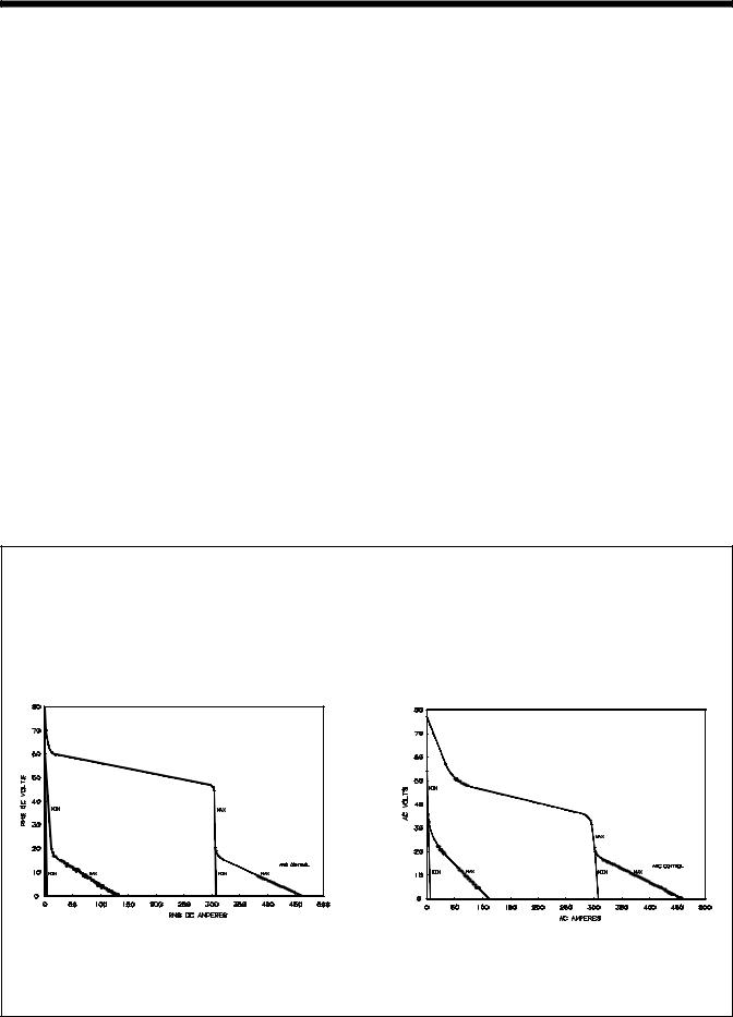
3-2. Volt-Ampere Curves
The volt-ampere curves show the minimum and maximum voltage and amperage output capabilities of the welding power source. Curves of other settings fall between the curves shown.
A. DC Mode |
|
B. AC Mode |
|
|
|
ssb1.1 10/91 – SB-116 199 / SB-116 200
TM-353 Page 6 |
Syncrowave 250 |
3-3. Duty Cycle And Overheating
Duty Cycle is percentage of 10 minutes that unit can weld at rated load without overheating.
If unit overheats, thermostat opens, output stops, light goes on (CE models only), and cooling fan runs. Wait fifteen minutes for unit to cool. Reduce amperage or duty cycle before welding.
Y Exceeding duty cycle can damage unit and void warranty.
40% Duty Cycle At 250 Amperes (60 Hz Models Only)
4 Minutes Welding |
6 Minutes Resting |
60% Duty Cycle At 200 Amperes
6 Minutes Welding |
4 Minutes Resting |
Overheating
0 |
A |
|
15 |
|
OR |
Minutes |
Reduce Duty Cycle |
|
duty1 4/95 / SB-116 198
Syncrowave 250 |
TM-353 Page 7 |
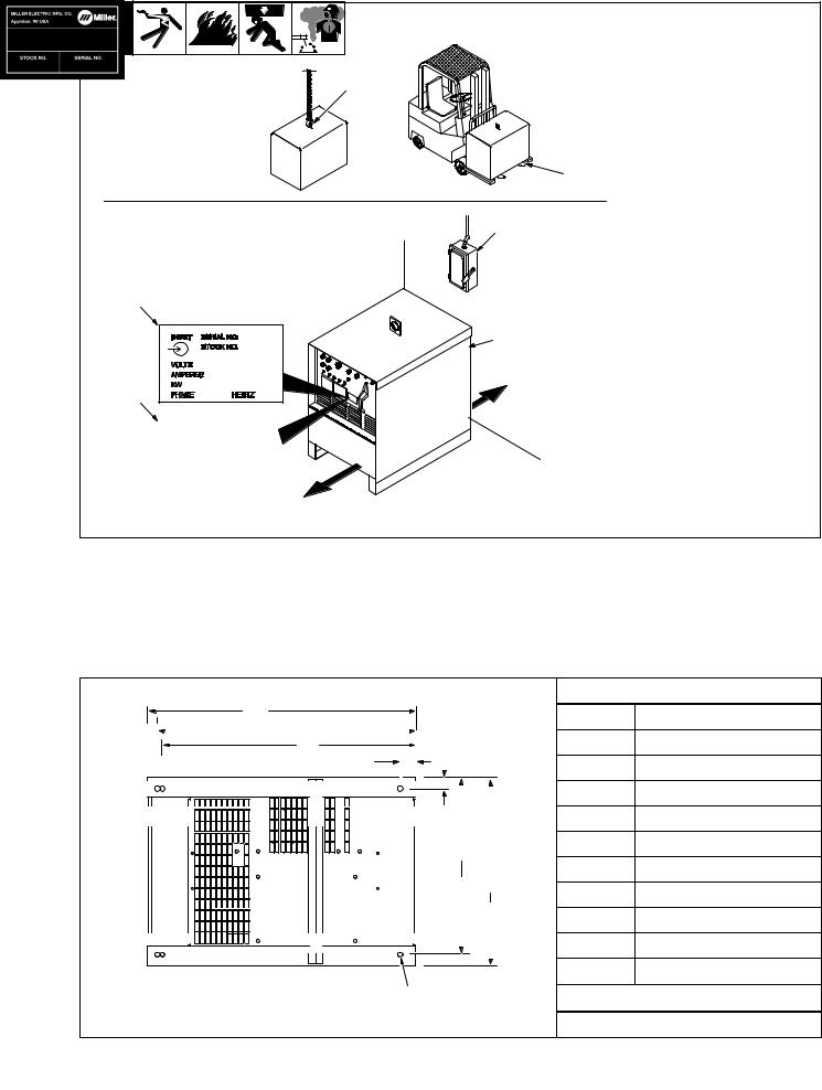
3-4. Selecting A Location
Movement |
1 |
|
OR
2
Location And Airflow
6
3
4
18 in (460
mm)
5
18 in (460 mm)
1Lifting Eye
2Lifting Forks
Use lifting eye or lifting forks to move unit.
If using lifting forks, extend forks beyond opposite side of unit.
3Rating Label (Non CE Models
Only)
4Rating Label (CE Models Only, See Section 2-2)
Use rating label to determine input power needs. CE label located on rear panel.
5Plate Label (CE Models Only)
6Line Disconnect Device
Locate unit near correct input power supply.
YSpecial installation may be required where gasoline or volatile liquids are present – see NEC Article 511 or CEC Section 20.
ST-800 402 / ST-117 264-F
3-5. Dimensions And Weights
|
|
|
Dimensions |
|
|
A |
|
Height |
30-3/4 in |
(781 mm) |
|
|
|
||||
B |
|
Width |
19-3/4 in |
(502 mm) |
|
C |
|
||||
E |
|
|
|
||
D |
Length |
27-1/2 in |
(698 mm) |
||
|
|||||
|
|
||||
|
|
A |
27 in (686 mm) |
||
|
|
B |
26 in (661 mm) |
||
|
F |
C |
25-1/4 in |
(642 mm) |
|
|
|
|
|
||
Front |
|
D |
1-1/2 in |
(38 mm) |
|
|
|
G |
|
|
|
|
|
E |
1-1/8 (29 mm) |
||
|
|
F |
17-7/8 (454 mm) |
||
|
|
G |
19-1/4 (489 mm) |
||
|
|
H |
1/2 in (13 mm) Dia |
||
H |
6 Holes |
|
Weight |
|
|
|
|
ST-154 792-B |
|
|
|
|
|
|
355 lbs (161 kg) |
||
TM-353 Page 8 |
|
|
|
Syncrowave 250 |
|
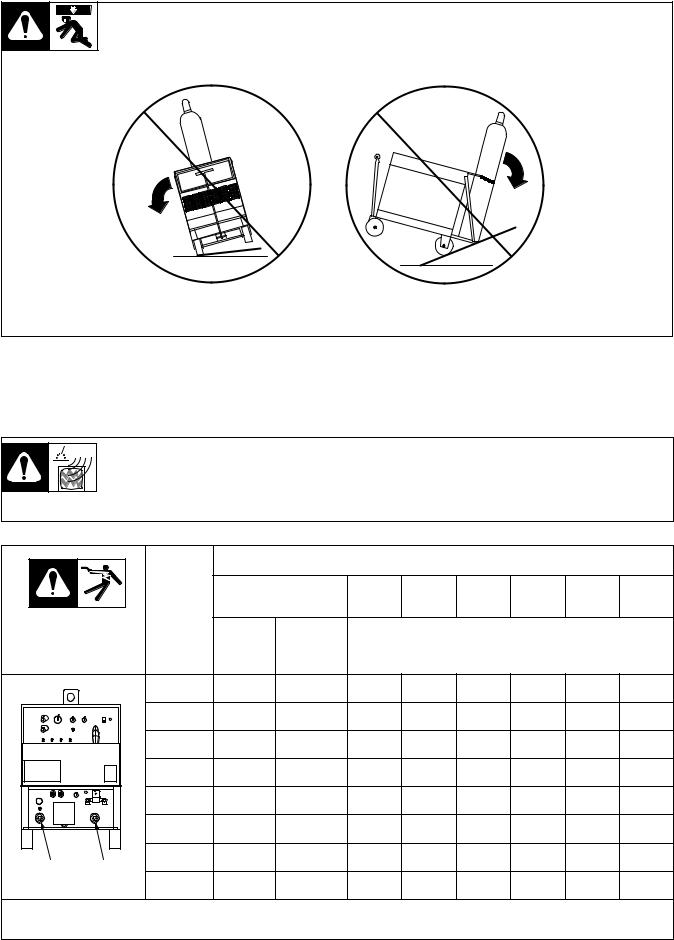
3-6. Tipping
Y Be careful when placing or moving unit over uneven surfaces.
3-7. Weld Output Terminals And Selecting Cable Sizes
Y ARC WELDING can cause Electromagnetic Interference.
To reduce possible interference, keep weld cables as short as possible, close together, and down low, such as on the floor. Locate welding operation 100 meters from any sensitive electronic equipment. Be sure this welding machine is installed and grounded according to this manual. If interference still occurs, the user must take extra measures such as moving the welding machine, using shielded cables, using line filters, or shielding the work area.
|
|
|
Total Cable (Copper) Length In Weld Circuit Not Exceeding |
|
|||||
|
|
100 ft (30 m) Or Less |
150 ft |
200 ft |
250 ft |
300 ft |
350 ft |
400 ft |
|
|
|
(45 m) |
(60 m) |
(70 m) |
(90 m) |
(105 m) |
(120 m) |
||
|
|
|
|
||||||
Weld Output |
Welding |
10 – 60% |
60 – 100% |
|
|
|
|
|
|
Duty |
Duty |
|
|
10 – 100% Duty Cycle |
|
||||
Terminals |
Amperes |
|
|
|
|||||
Cycle |
Cycle |
|
|
|
|
|
|
||
|
|
|
|
|
|
|
|
||
|
100 |
4 |
4 |
4 |
3 |
2 |
1 |
1/0 |
1/0 |
|
150 |
3 |
3 |
2 |
1 |
1/0 |
2/0 |
3/0 |
3/0 |
|
200 |
3 |
2 |
1 |
1/0 |
2/0 |
3/0 |
4/0 |
4/0 |
|
250 |
2 |
1 |
1/0 |
2/0 |
3/0 |
4/0 |
2-2/0 |
2-2/0 |
|
300 |
1 |
1/0 |
2/0 |
3/0 |
4/0 |
2-2/0 |
2-3/0 |
2-3/0 |
|
350 |
1/0 |
2/0 |
3/0 |
4/0 |
2-2/0 |
2-3/0 |
2-3/0 |
2-4/0 |
Work Electrode |
400 |
1/0 |
2/0 |
3/0 |
4/0 |
2-2/0 |
2-3/0 |
2-4/0 |
2-4/0 |
|
|
|
|
|
|
|
|
|
|
ST-154 795-C |
500 |
2/0 |
3/0 |
4/0 |
2-2/0 |
2-3/0 |
2-4/0 |
3-3/0 |
3-3/0 |
Weld cable size (AWG) is based on either a 4 volts or less drop or a current density of at least 300 circular mils per ampere. Contact your distributor for the mm2 equivalent weld cable sizes.
Syncrowave 250
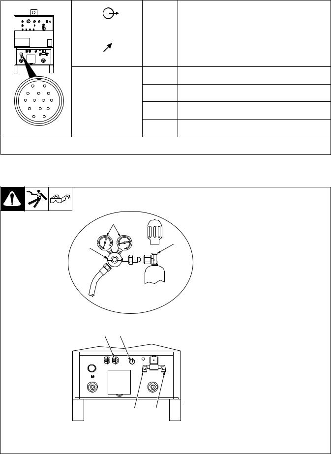
3-8. Remote 14 Receptacle
A |
J |
|
B |
K |
I |
|
|
|
C |
L N |
H |
D |
M |
G |
|
E |
F |
ST-154 795-C
|
|
|
Socket* |
Socket Information |
|
|
|
|
|
|
|
|
|
|
|
|
|
A |
24 volts ac. |
|
|
|
|
|
|
|
|
B |
Contact closure to A completes 24 volts ac contactor control |
|
|
|||
|
|
|
|
circuit. |
CCommand reference; 0 to +10 volts dc output to remote control.
DRemote control circuit common.
A
E |
0 to +10 volts dc input command signal from remote control. |
K Chassis common.
*The remaining sockets are not used.
3-9. 115 Volts AC Duplex Receptacle And Shielding Gas Connections
Y Turn Off power before connecting to receptacle.
1 115 V AC Receptacle
Receptacle is protected from over- 5 load by circuit breaker CB1 (see
Section 7-2).
|
|
2 |
Gas Valve In Fitting |
6 |
4 |
3 |
Gas Valve Out Fitting |
|
Fittings have 5/8-18 right-hand |
||
|
|
||
|
|
threads |
|
|
|
4 |
Cylinder Valve |
|
|
Open valve slightly so gas flow |
|
|
|
blows dirt from valve. Close valve. |
|
|
|
5 |
Regulator/Flow Gauge |
|
|
6 |
Flow Adjust |
|
|
Typical flow rate is 20 cfh (cubic feet |
|
|
|
per hour) (9.4 L/min) |
|
|
|
7 |
High Frequency Control (see |
|
|
|
Section 4-1) |
1 |
7 |
|
|
3 2
Ref. ST-154 795-C / Ref. ST-157 858
TM-353 Page 10 |
Syncrowave 250 |

3-10. Electrical Service Guide
NOTE
All values calculated at 60% duty cycle.
60 Hertz Models |
|
Without Power Factor |
With Power Factor Correction |
||||||
|
|
Correction |
|
||||||
|
|
|
|
|
|
|
|
||
|
|
|
|
|
|
|
|
|
|
Input Voltage |
200 |
|
230 |
460 |
575 |
200 |
230 |
460 |
575 |
|
|
|
|
|
|
|
|
|
|
Input Amperes At Rated Output |
85 |
|
74 |
37 |
30 |
55 |
48 |
24 |
19 |
|
|
|
|
|
|
|
|
|
|
Max Recommended Standard Fuse Or Circuit |
125 |
|
110 |
60 |
45 |
80 |
70 |
35 |
30 |
Breaker Rating In Amperes |
|
||||||||
|
|
|
|
|
|
|
|
|
|
|
|
|
|
|
|
|
|
|
|
Min Input Conductor Size In AWG/Kcmil |
4 |
|
6 |
10 |
10 |
8 |
8 |
12 |
14 |
|
|
|
|
|
|
|
|
|
|
Max Recommended Input Conductor Length |
173 |
|
158 |
291 |
455 |
86 |
114 |
186 |
189 |
In Feet (Meters) |
(53) |
|
(48) |
(89) |
(139) |
(26) |
(35) |
(58) |
(48) |
|
|
|
|
|
|
|
|
|
|
Min Grounding Conductor Size In AWG/Kcmil |
6 |
|
6 |
10 |
10 |
8 |
8 |
12 |
14 |
|
|
|
|
|
|
|
|
|
|
Reference: 1996 National Electrical Code (NEC) |
|
|
|
|
|
|
|
|
S-0092-J |
|
|
|
|
|
|
|
|
|
|
50 Hertz Models |
Without Power Factor Correction |
With Power Factor |
||||||||
|
Correction |
|
||||||||
|
|
|
|
|
|
|
|
|||
|
|
|
|
|
|
|
|
|
|
|
Input Voltage |
220 |
260 |
380 |
415 |
520 |
220 |
|
380 |
|
415 |
|
|
|
|
|
|
|
|
|
|
|
Input Amperes At Rated Output |
77 |
65 |
45 |
41 |
33 |
64 |
|
37 |
|
34 |
|
|
|
|
|
|
|
|
|
|
|
Max Recommended Standard Fuse Or Circuit |
125 |
100 |
70 |
60 |
50 |
90 |
|
60 |
|
50 |
Breaker Rating In Amperes |
|
|
||||||||
|
|
|
|
|
|
|
|
|
|
|
|
|
|
|
|
|
|
|
|
|
|
Min Input Conductor Size In AWG/Kcmil |
6 |
6 |
8 |
8 |
10 |
6 |
|
10 |
|
10 |
|
|
|
|
|
|
|
|
|
|
|
Max Recommended Input Conductor Length |
145 |
202 |
291 |
347 |
372 |
145 |
|
291 |
|
347 |
In Feet (Meters) |
(44) |
(62) |
(89) |
(106) |
(113) |
(44) |
|
(89) |
|
(106) |
|
|
|
|
|
|
|
|
|
|
|
Min Grounding Conductor Size In AWG/Kcmil |
6 |
8 |
8 |
10 |
10 |
6 |
|
8 |
|
10 |
|
|
|
|
|
|
|
|
|
|
|
Reference: 1996 National Electrical Code (NEC) |
|
|
|
|
|
|
|
|
|
S-0092-J |
|
|
|
|
|
|
|
|
|
|
|
Syncrowave 250 |
TM-353 Page 11 |
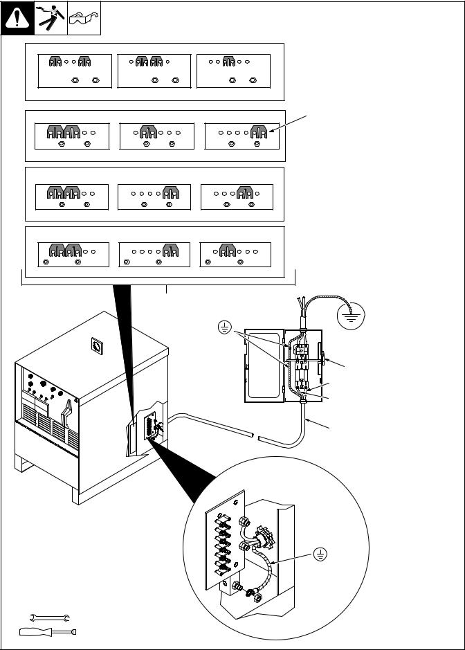
3-11. Placing Jumper Links And Connecting Input Power |
|
||||||||||
|
|
|
|
|
|
|
|
|
Check input voltage available at |
||
|
|
|
|
|
|
|
|
|
site. |
||
|
|
|
|
|
|
|
|
|
1 |
Jumper Link Label |
|
200 VOLTS |
230 VOLTS |
|
460 VOLTS |
|
Check label inside your unit– |
||||||
|
|
only one label is on unit. |
|||||||||
|
|
|
|
|
|
|
|
|
Y Only make connections for |
||
|
|
|
|
|
|
|
|
|
|
the voltages shown on the la- |
|
|
L |
L |
|
L |
L |
|
L |
L |
|
bel inside your unit. Do not |
|
|
|
|
|
|
|
|
|
|
|
make connections for any |
|
|
|
|
|
|
|
|
S-083 566-C |
|
other voltages. If jumper link |
||
|
|
|
|
|
|
|
|
|
|
label is missing from inside |
|
230 VOLTS |
|
|
460 VOLTS |
|
575 VOLTS |
2 |
unit, check rating label (see |
||||
|
|
|
|
Section 3-4) for allowable in- |
|||||||
|
|
|
|
|
|
|
|
|
|
put voltages. |
|
|
L |
L |
|
L |
L |
|
L |
L |
2 |
Jumper Links |
|
|
|
|
Move jumper links to match input |
||||||||
|
|
|
|
|
|
|
S-010 587-B |
||||
|
|
|
|
|
|
|
voltage. |
||||
|
|
|
|
|
|
|
|
|
|||
|
|
|
|
|
|
|
|
|
3 |
Input And Grounding |
|
220 VOLTS |
|
380 VOLTS |
|
|
415 VOLTS |
|
|
Conductors |
|||
|
|
|
|
|
|
|
|
|
Select size and length using |
||
|
L |
L |
|
L |
L |
|
L |
L |
Section 3-10. |
||
|
|
|
4 |
Line Disconnect Device |
|||||||
|
|
|
|
|
|
|
S-131 783-A |
||||
|
|
|
|
|
|
|
Select type and size of overcurrent |
||||
|
|
|
|
|
|
|
|
|
|||
260 VOLTS |
380 VOLTS |
520 VOLTS |
protection using Section 3-10. |
||||||||
Reinstall side panel. |
|||||||||||
|
|
|
|
|
|
|
|
|
|||
L |
L |
|
L |
L |
|
L |
L |
|
Y Special installation may be |
||
|
|
|
|
required where gasoline or |
|||||||
|
|
|
|
|
|
|
S-047 672-A |
|
volatile liquids are present – |
||
|
|
|
|
|
|
|
|
|
|
see NEC Article 511 or CEC |
|
|
|
|
|
|
|
|
|
|
|
Section 20. |
|
|
|
|
|
1 |
|
Connect GND/PE |
|
|
|
||
|
|
|
|
|
|
|
|
|
|||
|
|
|
|
|
|
Conductor First |
|
|
|
||
|
|
|
|
|
|
|
|
|
GND/PE |
||
|
|
|
|
|
|
|
|
|
Earth Ground |
||
|
|
|
|
|
|
|
|
|
4 |
|
|
|
|
|
|
|
|
|
|
|
L1 (U) |
|
|
|
|
|
|
|
|
|
|
|
L2 (V) |
|
|
|
|
|
|
|
|
|
|
|
3 |
|
|
|
|
|
|
|
|
|
|
|
Connect GND/PE |
|
|
|
|
|
|
|
|
|
|
|
Conductor First |
|
|
Tools Needed: |
|
|
|
|
|
|
|
|
|
||
|
3/8 in |
|
|
|
|
|
|
|
|
||
|
3/8, 1/2, 7/16 in |
|
|
|
|
|
|
|
|||
|
|
|
|
|
|
|
|
|
|
ST-117 263-K |
|
TM-353 Page 12 |
|
|
|
|
|
|
|
|
|
Syncrowave 250 |
|
SECTION 4 – OPERATION
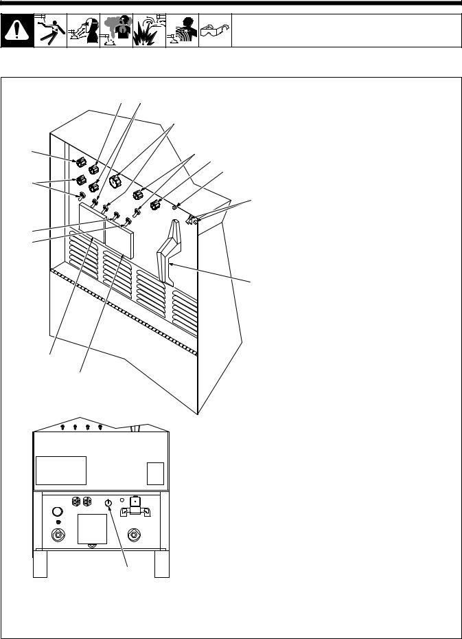
4-1. Controls
7 |
8 |
|
9 |
6 |
10 |
|
11 |
|
12 |
5 |
|
|
13 |
4 |
|
3 |
|
14
2
1
15
1 Ammeter
See Section 4-3.
2Voltmeter See Section 4-3.
3High Frequency Switch
See Section 4-11.
4Output (Contactor) Switch See Section 4-8.
5Spot Time Switch And Control (Optional)
See Section 4-5.
6 Preflow Time Control (Optional)
See Section 4-12.
7 AC Balance Control
See Section 4-6.
8 Crater Time Control And Switch
See Section 4-4.
9Amperage Adjustment Control And
Switch
See Section 4-7.
10 Arc Force (Dig) Switch And Control
See Section 4-9.
11 Postflow Time Control
See Section 4-10.
12High Temperature Shutdown Light (CE Models Only)
Lights when unit overheats and shuts down (see Section 3-3).
13 Power Switch And Pilot Light
Use switch to turn unit and light On and
Off.
14Output Selector Switch See Section 4-2.
15High Frequency Control
See Section 4-11.
Ref. ST-117 264-F / Ref. ST-154 795-C
Syncrowave 250 |
TM-353 Page 13 |

4-2. Output Selector Switch |
|
|
|
|
|
|
|
|
|
|
1 |
Output Selector Switch |
|
||
|
|
|
Y Do not |
use AC output in |
|||
|
|
|
|
damp areas, if movement is |
|||
|
|
|
|
confined, or if there is dan- |
|||
|
|
1 |
|
ger of falling. Use AC output |
|||
|
|
|
|
ONLY if required for the |
|||
|
|
|
|
welding process, and then |
|||
|
|
|
|
use a remote control. |
|
||
|
|
|
Y Do not change position of |
||||
|
|
|
|
switch |
while |
welding |
or |
|
|
|
|
while under load. |
|
||
|
|
|
Use switch to select (DCEN) Direct |
||||
|
|
|
Current Electrode Negative, AC, or |
||||
|
|
|
(DCEP) Direct Current Electrode |
||||
|
|
|
Positive output without changing |
||||
|
|
|
weld output cable connections. |
|
|||
|
|
|
|
|
|
Ref. ST-181 675-A |
|
4-3. |
Meters |
|
|
|
|
|
|
|
|
|
1 |
Voltmeter |
|
|
|
|
1 |
2 |
Voltmeter displays voltage at the |
||||
|
|
|
weld output terminals, but not nec- |
||||
|
|
|
essarily the welding arc due to |
||||
|
|
|
cable resistance, poor connec- |
||||
|
|
|
tions, etc. |
|
|
|
|
|
|
|
2 |
Ammeter |
|
|
|
|
|
|
Ammeter displays weld amperage |
||||
|
|
|
output of unit. |
|
|
||
TM-353 Page 14 |
Syncrowave 250 |
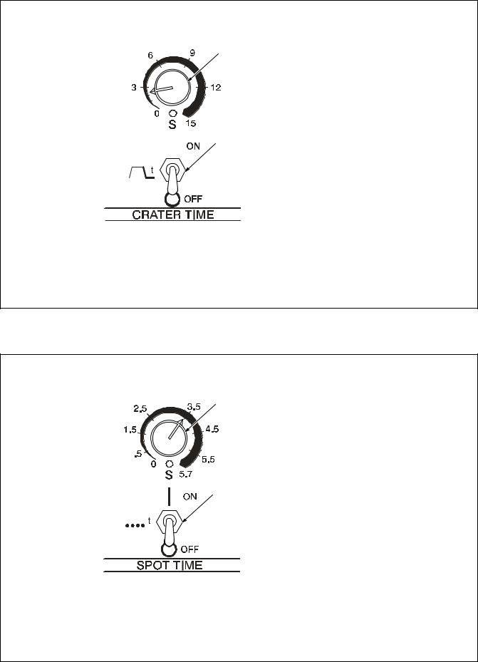
4-4. Crater Time Controls
|
|
|
|
1 |
Crater Time Control |
|
|
|
|
Use control to reduce current over a |
|
|
|
|
|
set period of time (0–15 seconds) at |
|
1 |
the end of the weld cycle when NOT |
||||
using a remote current control. |
|||||
|
|
|
|
2 |
Crater Time Switch |
|
|
|
|
ON – provides crater time. |
|
|
|
|
|
OFF – provides no crater time. |
|
|
|
|
|
Place switch in the OFF position for |
|
|
|
|
|
Shielded Metal Arc Welding |
|
|
|
|
|
(SMAW). |
|
|
|
|
|
Application: |
|
|
|
2 |
Crater Time should be used while |
||
|
|||||
|
|
|
|
GTAW welding materials that are |
|
|
|
|
|
crack sensitive, and/or the operator |
|
|
|
|
|
wants to eliminate the crater at the |
|
|
|
|
|
||
|
|
|
|
||
|
|
|
|
end of the weld. |
|
Note: This applies if the operator is using an on/off only type control to start and stop the welding process.
4-5. Spot Time Controls
2
1
1 Spot Time Switch
Place switch in the ON position to turn on spot weld circuitry.
The (GTAW) TIG Spot process is generally used with a direct current electrode negative (DCEN) set-up.
Place switch in the OFF position to turn off spot weld circuitry. Put switch in the OFF position while doing Shielded Metal Arc Welding
(SMAW).
2 Spot Time Control
Use control to set time (0–5.7 seconds) for Gas Tungsten Arc (GTAW) spot welds. Spot time begins at arc initiation. If the arc is broken during the spot time cycle, the timer stops but does not reset. When the spot time has ended, weld output stops. Postflow starts when the remote contactor is opened. The spot timer resets after the contactor opens.
Application:
TIG spot welding is used for joining thinner materials that are in close contact, with the fusion method. A good example would be joining coil ends.
Syncrowave 250 |
TM-353 Page 15 |
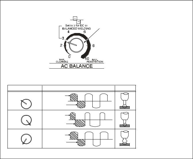
4-6. AC Balance Control
1
Setting |
Output Waveforms |
Arc |
Balanced |
50% Electrode |
|
3 |
Positive |
|
|
50% Electrode |
|
|
Negative |
|
More Penetration |
32% Electrode |
|
|
|
Positive |
|
68% Electrode |
10 |
Negative |
More Cleaning |
55% Electrode |
|
|
|
Positive |
|
45% Electrode |
0 |
Negative |
|
1 AC Balance Control
Balance Control (AC GTAW):
Control changes the AC output square wave. Rotating the control towards 10 provides deeper penetration. Rotating the control towards 0 provides more cleaning action of the workpiece.
When the control is in the Balanced position, the wave shape provides equal penetration and cleaning action.
Application:
When welding on oxide forming materials such as aluminum or magnesium, excess cleaning is not necessary. To produce a good weld, only a minimal amount, approximately a 0.10 in (2.5mm) of etched zone along the weld toes is required.
Set control to 7 and adjust as necessary. Joint configuration, set-up, process variables, and oxide thickness may affect setting.
Arc rectification can occur when welding above 200 amps and/or while welding with helium gas. If this condition occurs, increasing the Balance control towards maximum penetration, may help to restabilize the arc.
Ref. S-0795-A
TM-353 Page 16 |
Syncrowave 250 |
4-7. Amperage Adjustment Controls
1 Amperage Adjustment Control
Use control to adjust amperage, and preset amperage on ammeter 1 (see Section 4-3). This control may
be adjusted while welding.
For remote amperage control, front panel control setting is the maximum amperage available. For example: If front panel control is set to 200 A, the range of the remote amperage control is 5 to 200 A.
For spot welding, use Amperage Adjust control to select from 5–310 amps of peak amperage (see Section 4-5).
|
2 Amperage Control Switch |
|
Use switch to select way of control- |
|
ling amperage adjustment. |
|
For front panel control, place switch |
|
in the PANEL position. |
2 |
For remote control, place switch in |
|
REMOTE 14 position, and connect |
remote control device (see Section 3-8).
4-8. Output (Contactor) Control Switch
|
|
|
|
Y Weld output terminals are |
|
|
|
|
energized when Output |
|
|
|
|
(Contactor) switch is On and |
|
|
|
|
Power is On. |
|
|
|
|
|
|
|
1 |
1 Output/Contactor Switch |
|
|
||||
|
|
|
|
Use switch to select way of control- |
|
|
|
|
ling unit output. |
For front panel control, place switch in ON position.
When On is selected, HF and gas control are disabled.
For remote control, place switch in REMOTE 14 position, and connect remote control device (see Section
3-8).
Syncrowave 250 |
TM-353 Page 17 |
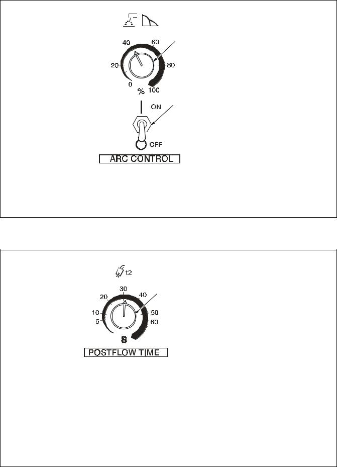
4-9. Arc Controls
|
1 |
Arc Control (Dig) |
|
For AC And DC SMAW Welding |
|
|
When set at 0, short-circuit amper- |
|
|
age at low arc voltage is the same |
|
1 |
as normal welding amperage. |
|
|
|
|
|
When setting is increased, short- |
|
|
circuit amperage at low arc voltage |
|
|
increases. |
|
|
Set at 0 for GTAW welding. |
|
|
2 |
Arc Control Switch |
|
Place switch in the ON position to |
|
|
turn on arc control circuitry. When |
|
|
switch is in the OFF position, no ad- |
|
2 |
ditional amperage is available at |
|
|
low arc voltages. Place switch in |
|
the OFF position while performing Gas Tungsten Arc Welding (GTAW).
Application:
Control helps arc starting or making vertical or overhead welds by increasing amperage at low arc voltage, and reduces electrode sticking while welding.
4-10. Postflow Time Control
1 Postflow Time Control
Use control to set length of time (0–70 seconds) gas flows after welding stops. It is important to set enough time to allow gas to flow un-
1 til after the tungsten and weld puddle has cooled down.
Application:
Postflow is required to cool tungsten and weld, and to prevent contamination of tungsten and weld. Increase postflow time if tungsten or weld are dark in appearance.
TM-353 Page 18 |
Syncrowave 250 |
4-11. High Frequency Controls
1
2
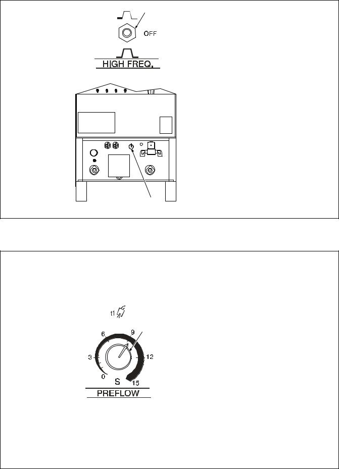
YPlace High Frequency switch in Off position before using the shielded metal arc welding (SMAW) process.
1 High Frequency Switch
START – (Up position) provides HF for arc starting only. High frequency turns on to help start arc when output is enabled. High frequency turns off when arc is started, and turns on whenever arc is broken to help restart arc.
Application:
HF Start is used when the DCEN GTAW process is required.
OFF – provides no HF. Use OFF for
SMAW (stick electrode) welding.
CONTINUOUS – (Down position) provides HF continuously throughout the weld.
Application:
HF Continuous is used when the AC GTAW process is required.
2High Frequency Intensity
Control
Use control to change amount of HF energy used to start and maintain the arc. Set as low as practical to prevent interfering with electronic equipment.
4-12. Preflow Time Control (Optional)
1 Preflow Time Control
Use control to set the length of time
(0–15 seconds) that gas flows before an arc is started.
Application:
Preflow is used to purge the immediate weld area of atmosphere. Preflow also aids in consistent arc starting.
1
Syncrowave 250 |
TM-353 Page 19 |
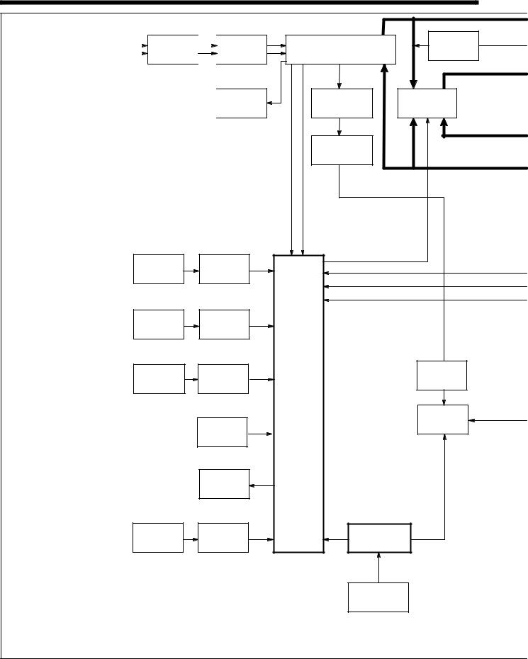
SECTION 5 – THEORY OF OPERATION
1 |
Input Terminal Board TE1 |
|
|
|
Provides means for operation on |
||||
different input voltages. |
|
|
||
|
|
|||
2 |
Power Switch S1 |
|
|
|
1-Phase |
||||
|
|
|||
Provide on/off control of unit. |
Line |
|||
3 |
Fan Motor FM |
Input |
||
Power |
||||
Provides cooling of internal components.
4 Main Transformer T1
Supplies power to weld output circuit, various control circuits, main control board PC1, and fan motor FM.
5 Control Board PC1
Controls weld output by changing the SCR gate pulses (conduction times) after comparing current feedback to selected amperage signal.
Also provides input connections for switches S3, S5, S6, and S7.
1 |
|
1φ |
|
2 |
|
|
|||
Input |
|
|
|
Power |
Terminal |
|
|
|
Switch |
Board TE1 |
|
|
|
S1 |
|
|
|
|
|
|
3 |
|||
|
|
|
|
Fan |
|
|
|
|
Motor |
|
|
|
|
FM |
|
|
|
|
|
6Arc Control Switch S6 And
Control R2
R2 selects short-circuit amperage when S6 is On, and High Frequency control R13 is Off.
7Crater Time Switch S7 And Control R11
R11 selects crater time when S7 is on, and Amperage Control switch S5 is in Panel position.
8 Thermostat TP1
If T1 overheats, TP1 opens stopping all weld output.
9 Output (Contactor) Switch S3
Selects On or remote contactor control.
10 AC Balance Control R3
Controls changes to ac output square wave.
11Ammeter A1 And Voltmeter V1
Display weld amperage and voltage while welding.
12Amperage Control Switch S5
And Adjustment Control R1
R1 selects weld output amperage when S5 is in Panel.
13Remote 14 Filter Board PC2/Remote 14 Receptacle RC1
PC2 protects unit from high frequency, and RC1 connects remote amperage and contactor controls to power source.
14 Circuit Breaker CB1
Protects 115 volts ac duplex receptacle RC2 from overload.
6
Arc Control
R2
7
Crater Time
Control
R11
9
Output
(Contactor)
Switch S3
12
Amperage
Adjustment
Control R1
6
Arc Control
Switch
S6
7
Crater Time
Switch
S7
8
Thermostat
TP1
10
AC Balance
Control
R3
11♦
Ammeter
A1
12
Amperage
Control
Switch S5
1φ |
4 |
AC |
24 |
|
Background |
||
|
Main |
|
|
|
|
Power |
|
|
Transformer |
|
|
|
|
Source |
|
|
T1 |
|
|
|
|
|
|
|
115 VAC |
|
DC |
|
14 |
23 |
|
|
|
||
|
Circuit |
|
Main |
|
Breaker |
|
Rectifier |
|
CB1 |
|
SR1 |
15
115 VAC Duplex
Receptacle
RC2
|
115 VAC |
|
1φ |
, 10 VAC |
|
Synchronization |
SCR |
|
Signal |
Gating |
|
|
|
Signals |
5 |
|
|
Control |
|
|
Board |
|
|
PC1 |
|
|
|
|
16 |
|
|
Postflow |
|
|
Timer |
|
|
TD1 |
|
|
17 |
|
|
Gas |
|
|
Valve |
|
|
GS1 |
|
13 |
|
|
Remote 14 |
|
|
Filter Board |
|
|
PC2 |
|
|
13 |
|
|
Remote |
|
|
Amperage |
|
|
Control |
|
TM-353 Page 20 |
Syncrowave 250 |
|
28 |
|
26 |
25 |
Hall Device |
|
|
Stabilizer |
HD1 |
|
|
Z1 |
|
|
27 |
|
Line |
|
Filter |
|
FL1 |
|
|
|
30 |
|
|
|
Work Weld |
|
|
|
Output |
|
11♦ |
|
Terminal |
|
|
|
|
Output |
Voltmeter |
|
|
V1 |
|
|
|
Selector |
|
|
|
|
|
|
|
Switch |
|
|
30 |
S4 |
21 |
|
Electrode |
|
|
|
|
|
|
|
Weld Output |
|
|
High |
Terminal |
|
|
Frequency |
|
|
|
Coupling |
|
|
|
Coil T3 |
|
29 |
22 |
|
|
Integrated |
High |
|
Frequency |
||
Rectifier |
||
Intensity |
||
SR2 |
||
Control R13 |
||
|
Current Feedback
Voltage Feedback
Voltage Feedback
18♦
Preflow
Timer
TD3
18♦
Preflow Time
Control
R12
Switch
S9
AC Or DC Control
1φ Power
Weld Current Circuit
External Circuits
♦Optional
21
Spark Gaps G
Capacitor
C4
20
High
Frequency
Transformer
T2
115 VAC
19♦
Spot
Timer
TD2
19♦
Spot Time
Control
R10
19♦
Spot Time
Switch
S8
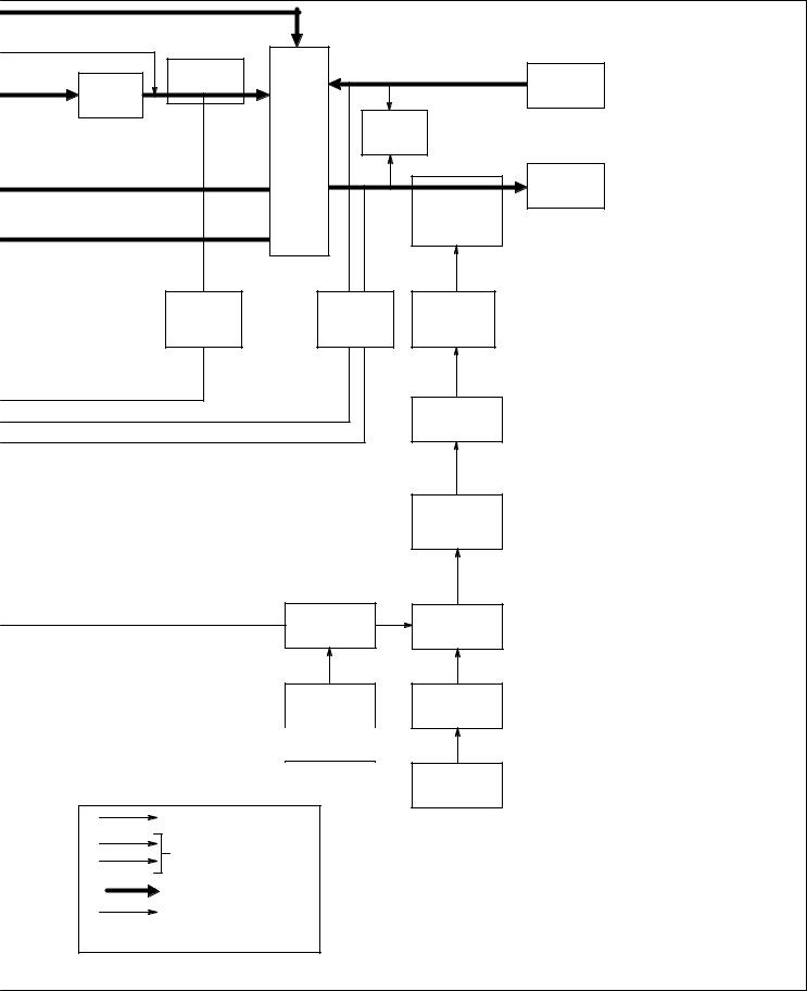
15115 Volts AC Duplex Receptacle RC2
Provides connection point for auxiliary equipment.
16 Postflow Timer TD1
Controls shielding gas and coolant postflow time.
17 Gas Valve GS1
Provides shielding gas during the weld cycle.
18Preflow Timer TD3, Control R12, And Switch S9
R12 selects time shielding gas flows before arc starts. S9 is an integral part of R12 so that when R12 is turned past zero (0), TD3 is off.
19Spot Timer TD2, Switch S8, And Control R10
R10 selects time output is available when spot welding. S8 selects Off or spot welding with remote contactor control.
20High Frequency Transformer T2
Steps up input voltage and charges capacitor C4.
21Spark Gaps G And High Frequency Coupling Coil T3
G provides path for C4 to discharge into T3. T3 supplies high-frequency to welding circuit.
22High Frequency Intensity Control R13
Changes amount of HF energy used to start and maintain the arc.
23 Main Rectifier SR1
Changes the ac output from T1 to full-wave rectified dc.
24 Background Power Source
Provides reduced weld output ripple at low weld output levels.
25 Stabilizer Z1
Smooths dc welding current.
26 Hall Device HD1
Provides current feedback signal to
PC1 through line filter FL1.
27 Line Filter FL1
Filters current feedback signal.
28 Output Selector Switch S4
Provides either AC or DC and output polarity.
29 Integrated Rectifier SR2
Provides dc voltage feedback to PC1.
30Electrode And Work Weld Output Terminals
Provide weld output.
Syncrowave 250 |
TM-353 Page 21 |

SECTION 6 – TROUBLESHOOTING
6-1. Troubleshooting Table
.
.
See Section 6-2 for test points and values and Section 10 for parts location.
Use MILLER Testing Booklet (Part No. 150 853) when servicing this unit.
Trouble |
Remedy |
|
|
|
|
Prior to Serial No. KG164875, no weld |
Be sure line disconnect switch is in the On position. |
output; unit completely inoperative – |
|
Effective with Serial No. KG164875, |
|
no weld output; unit completely inop- |
|
erative; PL2 off. |
|
|
|
|
Replace building line fuse(s) or reset circuit breaker(s) if open. |
|
|
|
Check for proper electrical input connections (see Section 3-11). |
|
|
|
Check for proper jumper link position (see Section 3-11). |
|
|
|
Check Power switch S1 and replace if necessary. |
|
|
Prior to Serial No. KG164875, no weld |
If using remote control, place Output (Contactor) switch S3 in Remote 14 position, and connect re- |
output; fan runs – Effective with Serial |
mote control to Remote 14 receptacle RC1 (see Sections 3-8 and Section 4-8). If remote is not being |
No. KG164875, no weld output; fan |
used, place Output switch S3 in On position. |
runs; PL2 on. |
|
|
|
|
Check, repair or replace remote control device. |
|
|
|
Allow a cooling period of approximately 15 minutes. If thermostats TP1 remain open, check continuity |
|
and replace if necessary (see Section 3-3). |
|
|
|
Check circuit breaker CB1, and reset if open (see Section 7-2). |
|
|
|
Place Output Selector switch S4 in desired position (see Section 4-2). |
|
|
|
Check optional preflow timer board TD3, and replace if necessary. |
|
|
|
Check optional spot timer relay TD2 for proper connections and resistance. Replace TD2 if |
|
necessary. |
|
|
|
Check continuity of Spot Time switch S8. Check condition of contacts. Repair or replace S8 if neces- |
|
sary. |
|
|
|
Check SR1, and replace necessary components. If components are replaced, check capacitors C7 |
|
thru C10. Replace capacitor(s) if necessary. |
|
|
|
Check control board PC1 and connections, and replace if necessary. |
|
|
|
Effective with Serial No. KB110695, check resistance and connections of HD1; HD1 is 1600 ohms |
|
± 10% between pins 1 and 3 of plug PLG3. Check input and output voltages. Replace HD1 if |
|
necessary. |
|
|
Unit provides only minimum weld |
Check position of Amperage Control switch S5 (see Section 4-7). |
output. |
|
|
|
|
Increase Amperage Adjustment control R1 setting if a remote control is used (see Section 4-7). |
|
|
|
Check, repair or replace remote control device. |
|
|
|
Check resistance and connections of Amperage Adjustment control R1; R1 is 1000 ohms ± 10%. |
|
Replace R1 if necessary. |
|
|
|
Check SCRs in main rectifier SR1, and replace if necessary. If any SCRs are replaced, Check capac- |
|
itors C7 through C10 for a short or open, and check for proper connections. Replace C7 through C10 |
|
if necessary. |
|
|
|
Check control board PC1 and connections, and replace if necessary. |
|
|
|
Effective with Serial No. KB110695, check resistance and connections of HD1; HD1 is 1600 ohms |
|
± 10% between pins 1 and 3 of plug PLG3. Check input and output voltages. Replace HD1 if |
|
necessary. |
|
|
Unit provides only maximum weld |
Check Amperage Adjustment control R1 for proper connections and resistance; R1 is 1000 ohms |
output. |
± 10%. Replace R1 if necessary. |
|
|
|
Effective with Serial No. KB110695, check resistance and connections of HD1; HD1 is 1600 ohms |
|
± 10% between pins 1 and 3 of plug PLG3. Check input and output voltages. Replace HD1 if |
|
necessary. |
|
|
|
Check connections for continuity to shunt device on units with Serial No. prior to KB110695. |
|
|
|
Check bypass capacitors C13, C14, C16, C17, C18, and C19 for broken leads, shorts, and leakage. |
|
Replace if necessary. |
|
|
TM-353 Page 22 |
Syncrowave 250 |
 Loading...